

Komatsu HM400-3 Articulated Dump Truck Shop Manual SEN05632-06 – Full Workshop Repair PDF
Original price was: $49.95.$29.95Current price is: $29.95.
Complete Komatsu HM400-3 Articulated Dump Truck Shop Manual (SEN05632-06) covering engine SAA6D140E-6, power train, hydraulics, electrical systems, troubleshooting, disassembly & assembly, maintenance standards, and full diagrams. Instant PDF download for serial numbers 3001 and up.
Description
Komatsu HM400-3 Articulated Dump Truck Shop Manual — SEN05632-06
This is the complete Komatsu HM400-3 Articulated Dump Truck Shop Manual, document number SEN05632-06, covering machines with serial numbers 3001 and up. It is the comprehensive workshop reference used for maintaining, diagnosing, repairing, and overhauling the HM400-3, with content spanning the engine, power train, steering, brakes, suspension, hydraulic system, electrical system, and body. Every major assembly and system is documented with specifications, testing procedures, troubleshooting flowcharts, disassembly and assembly steps, tightening torques, and maintenance standards.
File Details
- Manual Type: Shop Manual (Workshop / Service / Repair)
- Brand: Komatsu
- Model: HM400-3 Articulated Dump Truck
- Document Number: SEN05632-06
- Serial Number Range: 3001 and up
- Language: English
- File Format: PDF
- Page Count: Over 2,200 pages
Chapters Covered
The manual is organized into the following major sections:
- 00 — Index and Foreword: Safety notices, how to read the manual, maintenance standard terms, handling of fuel system devices, intake system parts, hydraulic equipment, electrical equipment, push-pull coupler procedures, electric wire codes, standard tightening torque tables, abbreviations, conversion tables.
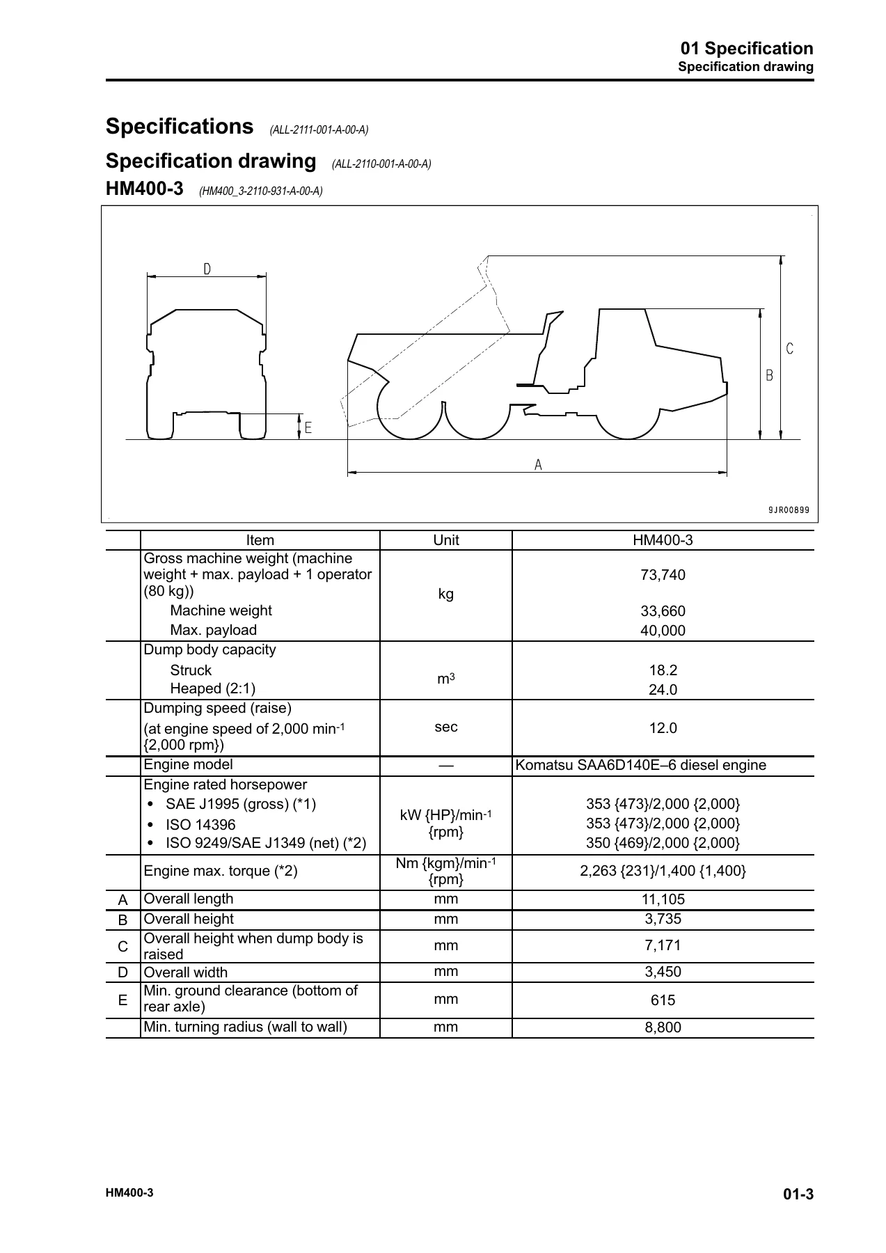
- 01 — Specification: Specification drawing, full specifications, weight table, fuel/coolant/lubricant table.
- 10 — Structure and Function: Engine and cooling system (engine related parts, output shaft, KVGT, EGR system piping and circuit, EGR valve, EGR cooler, KCCV layout and ventilator, KDPF, cooling system, radiator fan pump, aftercooler fan motor, radiator fan motor, oil cooler bypass valve). Power train (power train system, drive shaft, torque converter and transmission hydraulic piping, torque converter, transmission, transmission control valve, forward and reverse clutch ECMV, gear speed clutch ECMV, lockup clutch ECMV, differential lock clutch ECMV, main relief valve, torque converter relief valve, main flow selector valve, axle, differential, final drive). Steering system (layout, steering column, flow amplifier valve, steering valve, emergency steering pump). Brake system (layout of brake parts, parking brake solenoid and accumulator charge valve, accumulator, shut off solenoid valve, brake valve, proportional pressure reducing valve, slack adjuster, brake, brake system tank, parking brake). Undercarriage and frame (suspension, suspension cylinder, oscillation hitch). Hydraulic system (hydraulic component layout, dump body control, hydraulic tank, hoist valve, steering pump selector solenoid valve, dump EPC valve, center brake cooling remote motor, front brake cooling relief valve, center brake cooling relief valve). Cab and attachments (ROPS cab, cab tilt). Electrical system (electrical control system, transmission control system, machine monitor system, rear view monitor system, KOMTRAX system, system component parts, sensors).
- 20 — Standard Value Tables: Standard service value tables for engine and machine, including speeds, pressures, temperatures, and measurement conditions.
- 30 — Testing and Adjusting: Engine and cooling system (testing engine speed, boost pressure, exhaust gas temperature, exhaust gas color, adjusting valve clearance, compression pressure, blowby pressure, engine oil pressure, EGR valve and KVGT driving oil pressure, fuel pressure, cylinder cutout mode, no-injection cranking, fuel return rate and leakage, bleeding air from fuel circuit, fuel circuit leakage, radiator fan and aftercooler fan speed, alternator and A/C compressor belt, fuel doser cleaning, injector and engine controller compensation values). Power train (torque converter stall speed, power train oil pressure, transmission speed sensor, transmission controller, emergency retrieval of disabled machine, KTCS failure retrieval). Steering system (steering circuit oil pressure). Brake system (brake oil pressure, accumulator nitrogen gas pressure, braking performance, bleeding air, wheel brake disc wear, parking brake emergency release, parking brake pad wear). Hydraulic system (suspension cylinder, dump circuit oil pressure). Work equipment (dump body positioner sensor, body mount). Cab (cab tilt-up). Electrical system (setting and adjusting each equipment, special functions of machine monitor, KOMTRAX terminal start-up, engine controller voltage circuit, battery disconnect switch, Pm clinic).
- 40 — Troubleshooting: Troubleshooting points, sequence of events, checks before troubleshooting, classification and procedures, symptom and troubleshooting numbers, connector list and layout, connector contact identification, T-branch box and adapter table, fuse location table, precautions for KDPF cleaning and replacement, machine monitor troubleshooting, harness checker procedure, dummy temperature sensor preparation, short circuit connector preparation, failure codes table. Troubleshooting by failure code (display of code) covering all electrical and mechanical failure codes with detailed diagnostic procedures. Troubleshooting of electrical system (E-mode) covering engine starting, preheating, machine monitor, gauges, buzzers, lighting, turn signals, and more. Troubleshooting of hydraulic and mechanical system (H-mode) covering machine start, travel, shifting, torque converter, brakes, steering, dump body, and fan systems. Troubleshooting of engine (S-mode) covering starting, smoke, power, oil consumption, coolant, noise, vibration, regeneration, and more.
- 50 — Disassembly and Assembly: Engine and cooling system (supply pump, injector, cylinder head, radiator, cooling fan and fan motor for radiator, aftercooler, cooling fan and fan motor for aftercooler, engine assembly, front oil seal, rear oil seal, output shaft, KDPF, KCCV, air cleaner). Power train (transmission and front differential, front differential, torque converter, transmission, center differential, rear differential, front final drive and brake, center final drive and brake, rear final drive, center axle, rear axle). Steering system (steering cylinder, steering valve). Undercarriage and frame (front suspension cylinder, rear suspension cylinder, suspension cylinder, equalizer bar, front wheel, rear wheel, hitch frame). Hydraulic system (flow amplifier valve, hoist valve, hoist cylinder). Body (dump body). Cab and attachments (operator’s cab, cab glass, operator’s seat, seat belt). Electrical system (machine monitor, engine controller, retarder and hoist controller, transmission controller, mass air flow and temperature sensor, KOMTRAX terminal). Air conditioner unit.
- 60 — Maintenance Standard: Engine mount, output shaft, radiator fan pump, radiator fan motor, aftercooler fan motor. Drive shaft, torque converter and transmission mount, torque converter, transmission, transmission control valve, ECMVs, main relief valve, differential, axle, final drive. Steering column, steering cylinder, emergency steering pump. Slack adjuster, brake, parking brake. Suspension, suspension cylinder, oscillation hitch. Steering and hoist pump, pump for driving torque converter, transmission, aftercooler fan and center brake cooling motors, center brake cooling pump, brake charge pump, center brake cooling remote pump, center brake cooling remote motor, hoist valve, hoist cylinder.
- 80 — Appendix: Air conditioner components, refrigeration cycle, air conditioner unit, dual pressure switch, air conditioner controller, compressor, condenser, receiver drier, outer temperature sensor, testing and troubleshooting procedures, circuit diagrams, input and output signals, parts and connectors layout, air leakage testing, self-diagnosis testing, vent changeover testing, FRESH/RECIRC testing, dual pressure switch testing, relay testing, troubleshooting charts, failure codes related to air conditioner, power supply system troubleshooting, compressor and refrigerant system troubleshooting, blower motor system troubleshooting, FRESH/RECIRC air changeover troubleshooting, gauge pressure troubleshooting, service tool connection, air conditioner piping precautions, compressor oil handling.
- 90 — Diagrams and Drawings: Hydraulic circuit diagram (symbols, power train hydraulic circuit, full hydraulic circuit), electric circuit diagram (symbols, inside cab electric circuit diagrams, outside cab electric circuit diagrams, payload meter electric circuit diagram).
This shop manual is the definitive technical resource for the HM400-3. It provides the complete structure and function of every major system, the exact specifications and standard values needed for testing and adjusting, the full troubleshooting logic for every failure code and symptom, the step-by-step disassembly and assembly procedures with torque values and coating materials, and the maintenance standards with wear limits and repair criteria. Whether you are diagnosing an electrical fault, rebuilding a transmission, adjusting the suspension, or performing a full engine overhaul, the procedures, specifications, and diagrams in this manual are what you need to get the job done correctly.
What This Manual Enables You to Do
With the Komatsu HM400-3 Shop Manual SEN05632-06, you can confidently tackle everything from routine maintenance to major component overhauls. The manual covers the SAA6D140E-6 engine with its EGR, KVGT, KCCV, and KDPF systems, the full power train including the torque converter, transmission, differentials, and final drives, the steering and brake systems, the hydro-pneumatic suspension, the complete hydraulic system, and the complex electrical and machine monitor networks. You get the exact tightening torques, wear limits, pressure values, and diagnostic flowcharts that Komatsu technicians use.
Having the correct specifications and procedures is critical. Incorrect torque values, wrong adjustment clearances, or misdiagnosed electrical faults can lead to costly damage, repeated failures, and unsafe machine operation. This manual eliminates guesswork, giving you the precise information needed to perform repairs and adjustments that meet the manufacturer’s standards.
IMAGES PREVIEW
Delivery is instant via PDF download — no shipping, no waiting. The file can be viewed on any device, searched for quick reference, and printed if you prefer a physical copy in the workshop. Whether you are a professional technician, a fleet maintenance manager, or an owner-operator, this manual is an essential tool for keeping your HM400-3 running reliably.
Reviews
There are no reviews yet.