
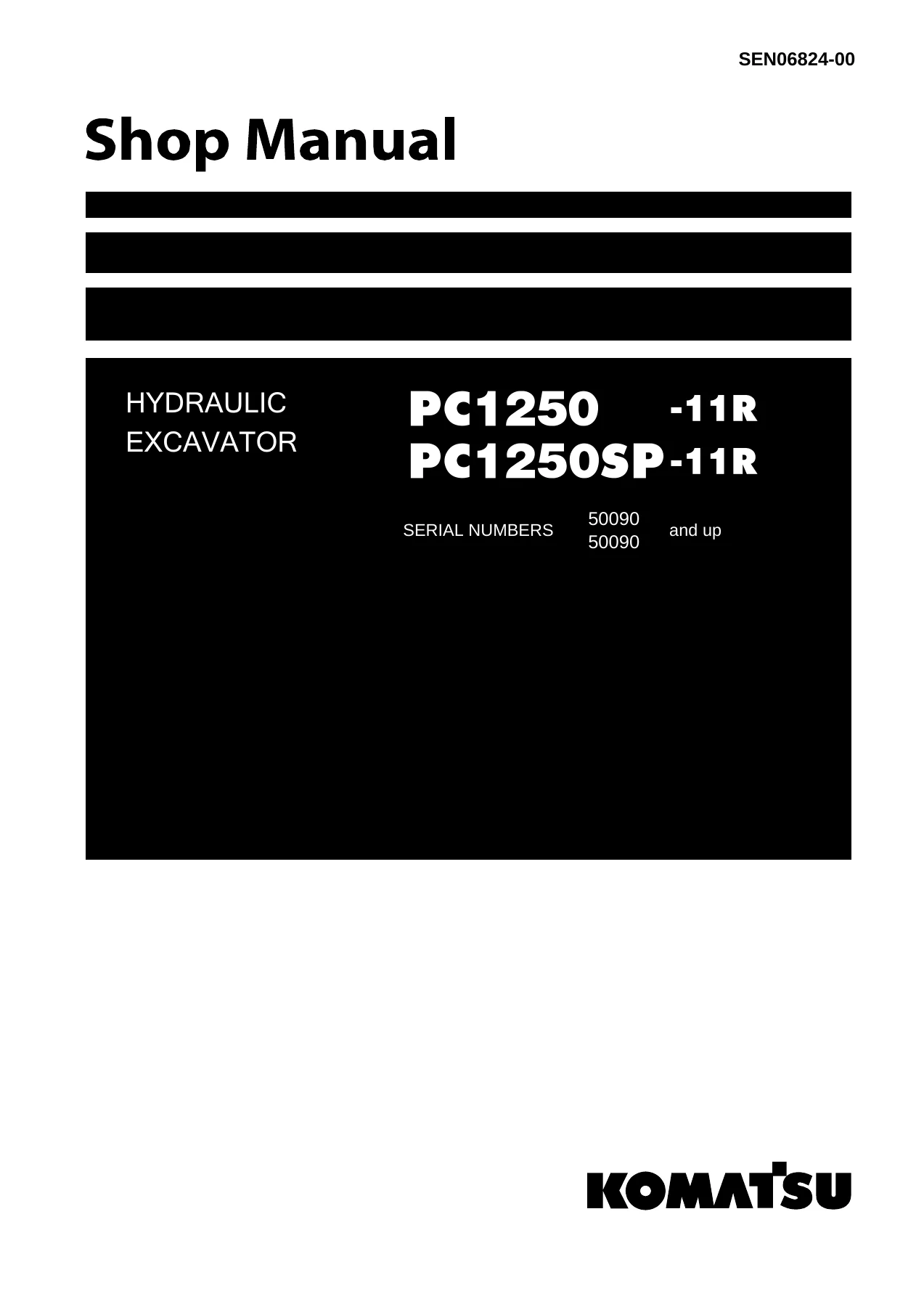
Komatsu PC1250-11R & PC1250SP-11R Hydraulic Excavator Shop Manual SEN06824-00 – PDF Download
Original price was: $59.95.$39.95Current price is: $39.95.
Complete Komatsu PC1250-11R and PC1250SP-11R Hydraulic Excavator Shop Manual (SEN06824-00) covering specifications, structure and function, testing and adjusting, troubleshooting, disassembly and assembly, maintenance standards, and circuit diagrams. Instant PDF download for serial numbers 50090 and up.
Description
Komatsu PC1250-11R & PC1250SP-11R Hydraulic Excavator Shop Manual SEN06824-00
This is the complete Komatsu Shop Manual for the PC1250-11R and PC1250SP-11R Hydraulic Excavators, document number SEN06824-00. It applies to serial numbers 50090 and up. This is the same comprehensive workshop manual used by Komatsu service technicians, covering every major system on these machines from the SAA6D170E-7 diesel engine through the hydraulic, electrical, and undercarriage systems.
File Details
- Manual Type: Shop Manual
- Brand: Komatsu
- Models: PC1250-11R, PC1250SP-11R
- Serial Numbers: 50090 and up
- Document Number: SEN06824-00
- Language: English
- Page Count: 2454
- File Format: PDF
- Date: 9-2021
Chapters Covered
- 00 INDEX AND FOREWORD
- 01 SPECIFICATIONS
- 10 STRUCTURE AND FUNCTION
- 20 STANDARD VALUE TABLE
- 30 TESTING AND ADJUSTING
- 40 TROUBLESHOOTING
- 50 DISASSEMBLY AND ASSEMBLY
- 60 MAINTENANCE STANDARD
- 80 APPENDIX
- 90 CIRCUIT DIAGRAMS
00 INDEX AND FOREWORD
This opening chapter provides the abbreviation list used throughout the manual, a comprehensive safety notice for operation, precautions to prevent fire, actions if fire occurs, precautions for disposing of waste materials, handling hydraulic equipment, disconnection and connection of pipings, handling electrical equipment, handling fuel system equipment, handling intake system equipment, practical use of KOMTRAX, disconnecting and connecting push-pull type couplers, precautions for disconnection and connection of connectors, and methods for disconnecting and connecting various connector types including Deutsch, slide lock, lock to pull, lock to push, and housing to rotate. It also includes how to read electrical wire code, explanation of terms for maintenance standard, standard tightening torque table, and conversion table.
01 SPECIFICATIONS
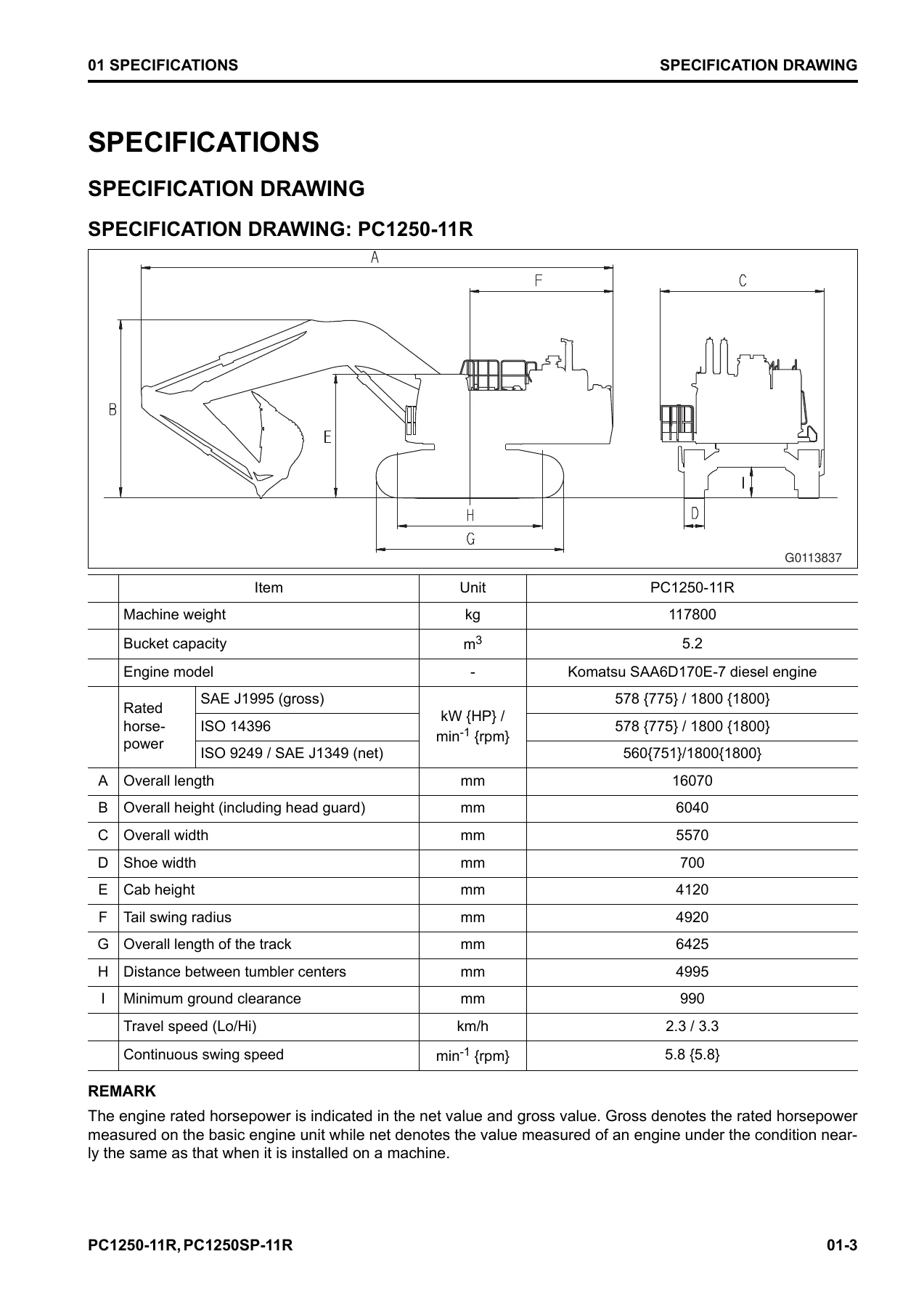
Covers the complete specifications for both the PC1250-11R and PC1250SP-11R models, including specification drawings, working range drawings, detailed specifications, weight tables, and the fuel, coolant, and lubricant table to meet ambient temperature requirements. Engine specifications include the Komatsu SAA6D170E-7 diesel engine with rated horsepower, maximum torque, displacement, and fuel consumption data. Undercarriage, hydraulic system, and working range figures are all included.
10 STRUCTURE AND FUNCTION
This major chapter provides detailed explanations of every system on the machine, including the boot-up system, system operating lamp system, battery disconnect switch, engine system with engine control, auto-deceleration, automatic low idle, automatic warm-up, overheat prevention, turbocharger protection, and automatic idle stop. It covers the cooling system with fan speed control, engine output control, and fan reverse rotation. The hydraulic system section covers OLSS, pump swash plate angle control, engine and pump combined control, and component parts including the hydraulic tank, main pump, control valve, and variable back pressure valve. Work equipment systems include machine push-up, heavy lift, boom shockless control, PPC lock, and automatic lock systems. The swing system, travel system, lifting system, undercarriage, work equipment, cab, and control system are all covered in detail with layout drawings, diagrams, and component part descriptions.
20 STANDARD VALUE TABLE
Contains the complete standard value tables for engine and machine, including PC1250-11R and PC1250SP-11R specific values. Engine tables cover performance, air intake and exhaust, main body, fuel system, lubrication system, cooling fan, and aftercooler fan. Machine tables cover engine speed, control valve spool stroke, travel of control lever, operating effort, work equipment and travel oil pressure, swing, traveling, hydraulic drift, work equipment speed, operation time lag, oil leakage, and cooling fan data. Also includes machine posture and procedure for measuring performance with reference figures.
30 TESTING AND ADJUSTING
This chapter provides all the tools for testing and adjusting, including sketches of tools, and covers engine and cooling system testing for engine speed, boost pressure, exhaust gas temperature, exhaust gas color, valve clearance, compression pressure, blowby pressure, engine oil pressure, fuel pressure, fuel return rate and leakage, bleeding air from fuel system, testing fuel circuit for leakage, testing supply pump, handling cylinder cut-out mode operation, testing alternator, handling no-injection cranking operation, and writing injector compensation value to engine controller. Power train, undercarriage and frame, hydraulic system, cab and its attachments, and electrical system sections cover releasing remaining pressure, testing and adjusting oil pressures, piston pump control oil pressure, servo piston stroke, outlet pressure of solenoid valve, PPC valve outlet pressure, swing PPC shuttle valve, adjusting work equipment and swing PPC valves, travel deviation, cooling fan speed, aftercooler fan speed, fan pump circuit oil pressure, fan pump EPC electric current, fan pump EPC solenoid valve outlet pressure, parts causing hydraulic drift, oil leakage, bleeding air from hydraulic circuit, cab tipping stopper, mirrors, and machine monitor setup and operation. Includes Pm Clinic service and performing Quick Pm.
40 TROUBLESHOOTING
The troubleshooting chapter begins with related information, general troubleshooting points, sequence of events, checks before troubleshooting, inspection procedure, and testing in accordance with testing procedure. It includes preparation for troubleshooting of electrical system, procedure for troubleshooting, symptom and troubleshooting numbers, information described in troubleshooting table, troubleshooting method for open circuit in wiring harness of pressure sensor system, connector list and layout, connector contact identification, T-branch box and T-branch adapter table, fuse location table, and failure code table. The bulk of the chapter covers troubleshooting by failure code with hundreds of specific codes, troubleshooting of electrical system (E-mode) with symptoms E-1 through E-61, troubleshooting for hydraulic and mechanical systems (H-mode) with symptoms H-1 through H-42, and troubleshooting of engine (S-mode) with symptoms S-1 through S-19.
50 DISASSEMBLY AND ASSEMBLY
Provides the abbreviation list, related information on disassembly and assembly, how to read the manual, coating materials list, special tools list, and sketches of special tools. Engine and cooling system covers removal and installation of supply pump assembly, injector assembly, cylinder head assembly, starting motor assembly, alternator belt, radiator assembly, hydraulic oil cooler assembly, aftercooler assembly, cooling fan motor assembly, engine, PTO, and hydraulic pump assembly, engine front and rear oil seals, fuel cooler assembly, engine hood assembly, fuel tank assembly, muffler assembly, bellows pipe assembly, air cleaner assembly, air conditioner compressor assembly, and air conditioner condenser assembly. Power train covers disassembly and assembly of PTO, final drive, swing machinery, and removal and installation of travel motor and final drive assembly, swing motor and swing machinery assembly, and swing circle assembly. Undercarriage and frame covers idler assembly, recoil spring, track roller, carrier roller, track link assembly in field, separation and connection of track assembly, idler assembly, idler adjustment cylinder, track roller assembly, carrier roller assembly, revolving frame assembly, and counterweight assembly. Hydraulic system covers center swivel joint assembly, hydraulic tank assembly, hydraulic pump assembly, control valve assembly, swing motor assembly, work equipment PPC valve assembly, travel PPC valve assembly, and grease gun assembly. Work equipment covers bucket cylinder, arm cylinder, boom cylinder, bucket assembly, arm assembly, boom assembly, work equipment cylinder assembly, and bottom dump cylinder assembly. Cab and its attachments covers top guard assembly, operator’s cab assembly, operator cab glass, front window assembly, floor frame assembly, air conditioner unit assembly, operator’s seat, seat belt, and front wiper assembly. Electrical system covers engine controller assembly, pump controller assembly, KomVision controller assembly, machine monitor assembly, crankcase pressure sensor, KomVision camera, KOMTRAX terminal assembly, KOMTRAX Plus controller assembly, and wireless LAN unit assembly.
60 MAINTENANCE STANDARD
Covers maintenance standards for engine and cooling system including engine mount, PTO, cooling system, cooling fan pump, EPC valve of cooling fan pump, and cooling fan motor. Power train covers swing circle, swing machinery, final drive, sprocket, and sprocket tooth profile full-scale drawing. Undercarriage and frame covers track frame and idler cushion, idler, track roller, carrier roller, track shoe, and double shoe. Hydraulic system covers main pump, swing motor, control valve, straight travel valve, variable back pressure valve, work equipment and swing PPC valve, travel PPC valve, solenoid valve, and center swivel joint. Work equipment covers work equipment linkage with dimensions of arm and bucket, boom cylinder, arm cylinder, and bucket cylinder.
80 APPENDIX
Covers the air conditioner system including precautions for refrigerant, air conditioner components, specifications, configuration and function of refrigeration cycle, outline of refrigeration cycle, component parts of air conditioner system, air conditioner unit, air conditioner controller, compressor, condenser, receiver drier, and sensors for air conditioner system. Also includes explanation of procedure for testing and troubleshooting of air conditioner, circuit diagram and arrangement of connector pins, air conditioner system diagram, input and output signals of air conditioner controller, installation locations of air conditioner parts and arrangement of connectors, testing air leakage, testing air conditioner using self-diagnosis function, testing vent changeover, testing fresh/recirc air changeover, testing sunlight sensor, testing pressure switch for refrigerant, testing relays, air conditioner troubleshooting charts, failure codes for air conditioner, troubleshooting for power supply system, compressor and refrigerant system, blower motor system, fresh/recirc air changeover, troubleshooting using gauge pressure, connection of service tool, precautions for disconnecting and connecting hoses and tubes in air conditioner pipings, and handling compressor oil.
90 CIRCUIT DIAGRAMS
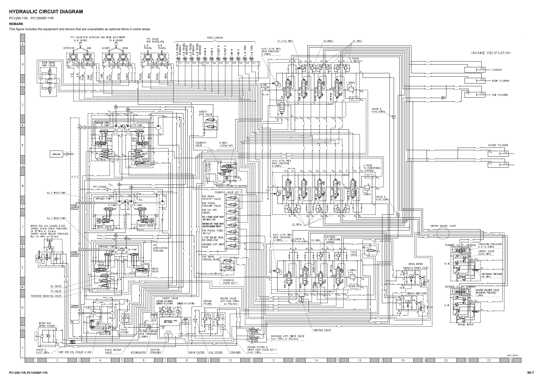
Contains the hydraulic circuit diagram with symbols used in hydraulic circuit diagram and the complete hydraulic circuit diagram, plus the electrical circuit diagram with symbols used in electrical circuit diagram and the complete electrical circuit diagram split across sixteen pages (1/16 through 16/16).
Why This Komatsu PC1250-11R & PC1250SP-11R Shop Manual Is Essential
Whether you are performing routine maintenance, diagnosing a fault code, rebuilding a hydraulic component, or carrying out a complete engine overhaul, this Komatsu PC1250-11R and PC1250SP-11R Shop Manual gives you the exact procedures, specifications, and tolerances that Komatsu factory technicians use. The PC1250-11R and PC1250SP-11R are large mining-class hydraulic excavators, and getting the repair right the first time matters. This manual covers the SAA6D170E-7 diesel engine, the full hydraulic system including main pumps and control valves, the swing and travel systems, undercarriage, work equipment, electrical system, air conditioner, and the complete circuit diagrams.
Every procedure is laid out step by step with tightening torques, clearances, adjustment values, and testing criteria. The troubleshooting sections include hundreds of failure codes with detailed diagnostic procedures, so you can pinpoint the problem quickly instead of guessing. The standard value tables give you the exact numbers for new machines and repair limits, so you know when a component is within spec and when it needs replacing. The disassembly and assembly chapter includes special tool references and coating material lists, so you can prepare properly before starting a job.
IMAGES PREVIEW
This is not a generic overview. It is the complete Komatsu PC1250-11R and PC1250SP-11R Hydraulic Excavator Shop Manual, document SEN06824-00, running 2454 pages and covering serial numbers 50090 and up. It is delivered as an instant PDF download, so you have it immediately after purchase. The file works on any device, can be printed for use in the workshop, and gives you the information you need whether you are servicing one machine or running a fleet. If you work on PC1250-11R or PC1250SP-11R excavators, this manual belongs in your service library.

Reviews
There are no reviews yet.