
Komatsu PC2000-8 Field Assembly Manual – Backhoe & Loading Shovel PDF
Original price was: $44.95.$26.95Current price is: $26.95.
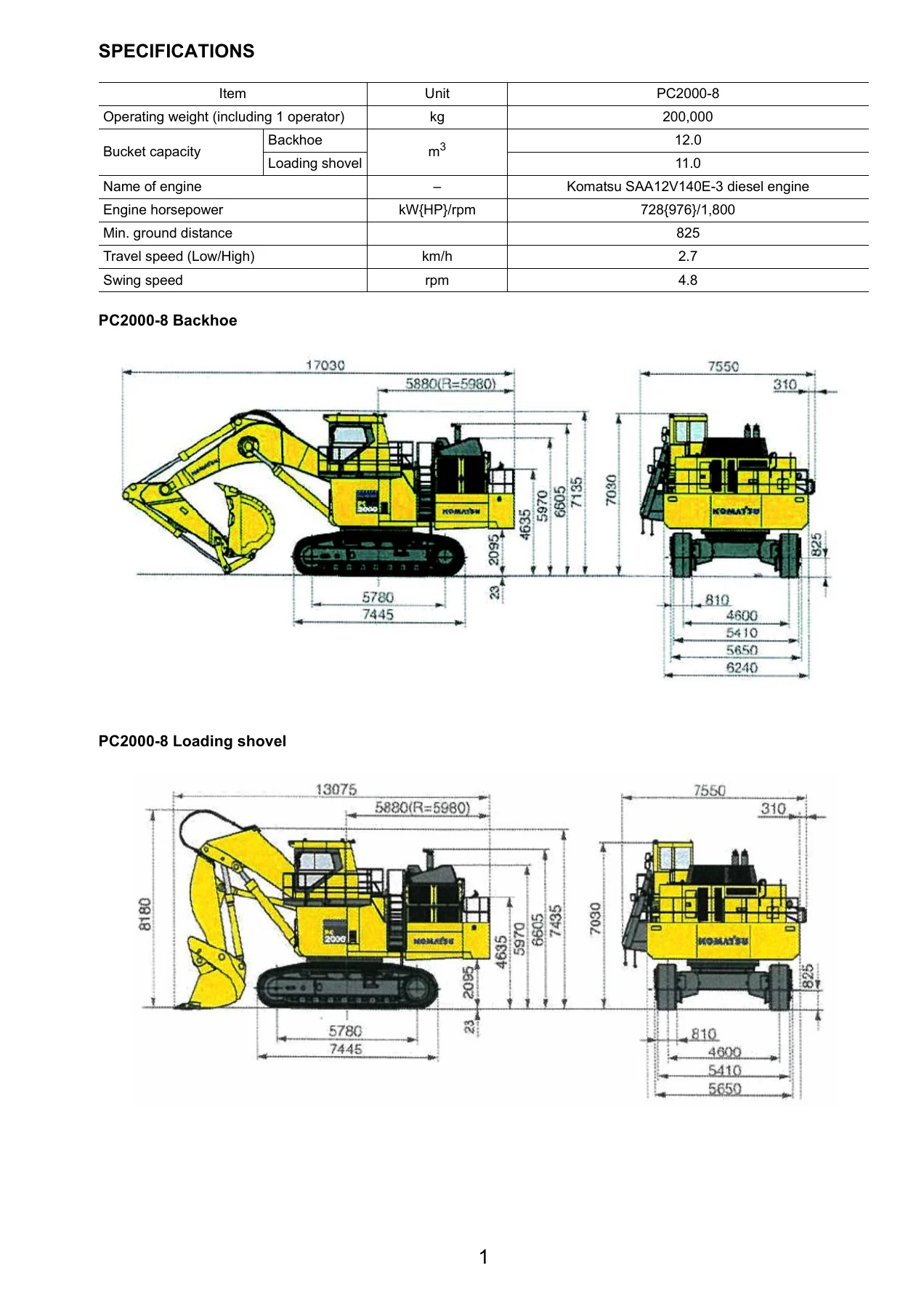
Komatsu PC2000-8 Field Assembly Manual covering chassis assembly, backhoe and loading shovel work equipment, power container coupling, air bleeding, torque tables and field assembly inspection. English PDF, approx. 330 pages.
Description
The Komatsu PC2000-8 Field Assembly Manual is the on-site assembly document for the PC2000-8 hydraulic excavator. The PC2000-8 is shipped from the factory divided into kits – center frame, crawler frames, revolving frame, power container, operator’s cab, counterweight, boom, arm, bucket and supporting exterior assemblies – because the complete machine cannot meet the transportation regulations of most routes. This manual is the reference the assembly team uses to turn those kits back into a working 200-tonne-class excavator in the field. It is written for the work supervisor, the work leader, the crane director, mechanics and interpreters working on the assembly, and it is also the document to consult when the machine later has to be divided again for transport.
Both PC2000-8 Backhoe and PC2000-8 Loading Shovel work equipment configurations are covered, with dedicated sections for each. The manual includes the safety-meeting requirement, the reference supervision system diagram, workplace selection criteria, protective gear and sling checks, and the in-progress checks the supervisor must enforce while slinging and lifting with cranes. It then proceeds step-by-step through chassis assembly, power container coupling, cab installation, counterweight mounting, work equipment attachment, air bleeding, torque confirmation, and final inspection.
File Details
- Manual type: Field Assembly Manual
- Brand: Komatsu
- Models covered: PC2000-8 (Backhoe and Loading Shovel)
- Engine: Komatsu SAA12V140E-3 diesel engine
- Language: English
- File format: PDF
- Page count: Approx. 330 pages
Chapters Covered
- A. Assembly of Chassis
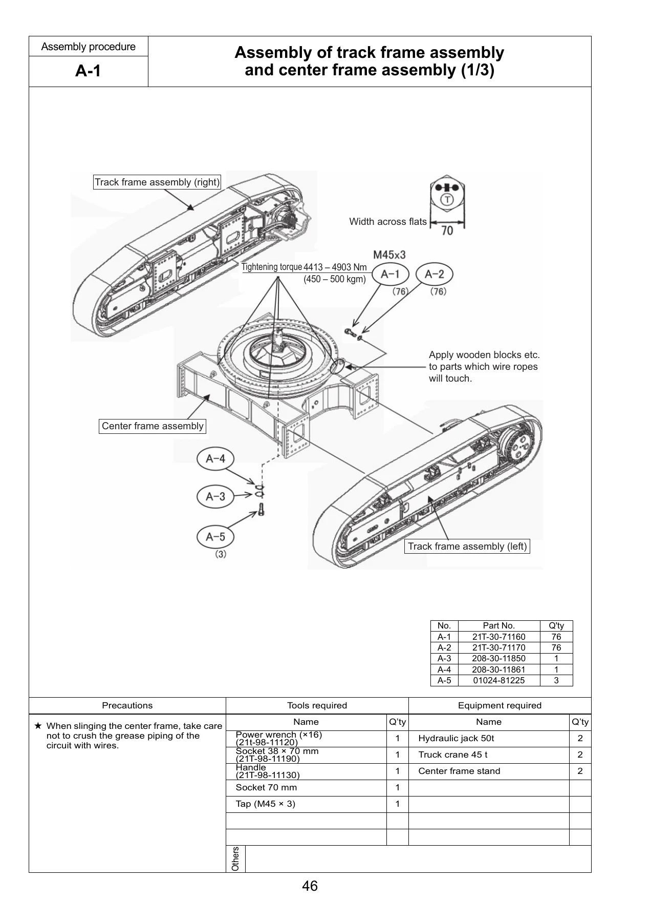
- A-1 to A-9 Assembly of undercarriage – track frame and center frame assembly, idler cushion cylinder piping, travel motor piping, travel motor cover, swing circle grease filling, revolving frame and undercarriage coupling, swing machinery/motor installation, swivel joint piping, swing circle grease piping
- A-10 to A-18 Assembly of upper structure – hydraulic tank, fuel tank, cab base, emergency escape ladder, left floor assembly, cab base piping and wiring, left floor heater piping
- A-19 to A-31 Coupling of power container – left floor wiring, tail pipe, power container assembly, suction piping, oil cooler piping, pump drain piping, fan motor drain piping, suction unit undercover, delivery piping, pilot piping and fan motor piping, fuel piping, air conditioner piping, heater piping, power container wiring
- A-32 to A-41 Operator’s cab – cab assembly, rotary lamp, ORBCOMM antenna, cab wiring, cab hydraulic piping, window washer hose, air conditioner piping, heater piping, rear floor assembly, handrail
- A-42 to A-56 Exterior parts and counterweight – track frame ladder, power container catwalks, right floor and grease can cover, fuel tank catwalks, exterior clearance adjustment, grease reel piping, access ladder, counterweight, deformation preventing stoppers, counterweight handrail, handrail clamps, fuel cut wire, drain piping, battery wiring
- A-57 to A-69 Starting engine and servicing – hydraulic tank strainer, engine start and air bleeding, track adjustment, swing circle bolt tightening, touch-up after assembly, engine heater port, optional harness, rear lamps, rear camera, emergency stop switches, engine and PTO oil piping, coolant piping, guard bracket
- C. Assembly of Backhoe
- C-1 to C-11 Coupling of boom – boom cylinder, boom cylinder hoses, boom sub assembly, boom assembly, boom cylinder head side, hoses between boom and chassis, arm assembly, arm cylinder, hoses between boom and arm, auto grease piping, wiring between boom and chassis
- C-12 to C-16 Coupling of bucket – bucket assembly, bucket link, cylinder air bleeding, touch-up after assembly, auto grease circuit air bleeding
- LS. Assembly of Loading Shovel Work Equipment
- LS-1 to LS-17 – arm cylinder bottom, boom cylinder to machine body, boom cylinder hoses, boom cylinder piping, boom assembly, boom cylinder head pins, hose between machine body and boom, bucket cylinder assembly, arm assembly, arm cylinder assembly, hoses between boom and arm, bucket cylinder hoses, grease feed hose of bucket cylinder, bucket assembly, arm cylinder junction hoses, bottom dump hose and grease feed hose, arm dump cushion
- M. Inspection and Servicing Procedures After Assembly
- M-1 to M-7 – oil and coolant level inspection, fuel and lubricant standards, hydraulic circuit flushing, residual pressure release, HIC circuit residual pressure and accumulator gas pressure, air conditioner refrigerant charging, installed angles of mirrors and lights
- VHMS Controller Initial Setting Procedure
- Machine information confirmation, PC connection, satellite capture confirmation, VHMS initial setting tool, controller initial settings, Quick Pm, download of setting data, disconnection, reporting
- Field Assembly Inspection Report (Backhoe and Loading Shovel)
- Pre-assembly oil and coolant checks, during-assembly checks, monitor checks, switch and lever operation, swing and travel performance, work equipment performance, torque and pressure measurement, hydraulic drift, operating effort and stroke
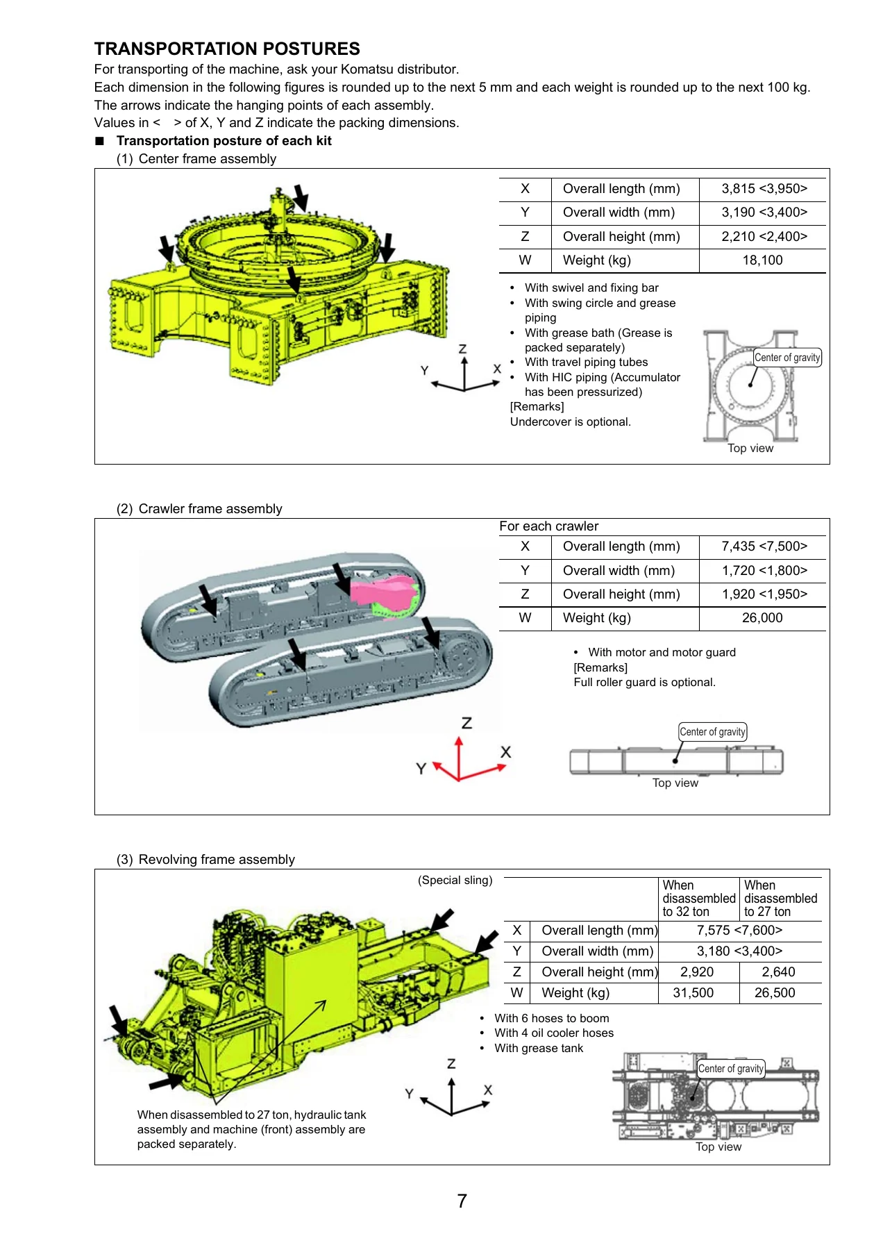
Beyond the procedural steps, the manual provides transportation posture data for each kit with overall length, width, height, weight and centre-of-gravity positions – essential for planning crane lifts and trailer loads. It also includes the full individual parts list for each assembly group, tightening torque tables for bolts not specified in the text, pipe thread tightening torque tables by material combination, hydraulic hose connecting nut torque tables, and proper socket sizes for M39 and larger bolts. The coating material list covers adhesives, gasket sealants, molybdenum disulfide lubricants, greases, primers and caulking materials with Komatsu part numbers.
Transportation and Lifting Data Included
- Centre frame assembly – dimensions, weight and sling points
- Crawler frame assembly – per-crawler dimensions and weight
- Revolving frame assembly – when disassembled to 32 t and 27 t
- Fuel tank assembly – dimensions, weight, working lamp and fuel level sensor
- Cab base assembly – dimensions, weight, head lamp and working lamp
- Left floor assembly – dimensions, weight, battery
- Power container assembly – dimensions, weight, super hood and radiator-side handrail
- Operator’s cab assembly – dimensions, weight, antenna and mirror fold positions
- Counterweight assembly – dimensions, weight, separately packed handrail and bolts
- Catwalk assemblies – power container side, right, front, cab L.H. and cab front
- Switch box assembly, right floor assembly, cab rear floor assembly
- Boom, arm, bucket, arm cylinder tube, hydraulic tank, swing machinery assemblies
Torque and Tightening Reference
- Bolt tightening torque table for bolts not specified in text (M6 through M39)
- Pipe thread tightening torque for mild steel or cast iron male screws (Table 2)
- Pipe thread tightening torque for refined/heat-treated male screws (Table 3)
- Hydraulic hose connecting nut tightening torque (Table 4)
- Proper socket sizes for M39 and larger hexagon bolts (Table 5)
- Application of LT-1, LT-2, LT-3, LT-4, LG-1, LG-5, LG-6, LG-7 and equivalent adhesives and sealants
Assembly is not just bolting parts together. The PC2000-8 Field Assembly Manual specifies the tightening order for the track frame coupling bolts (76 bolts at M45xP3, 450-500 kgm), the correct sequence for filling the swing circle grease bath, the exact projecting lengths for the HIC cylinder plungers (135+/-5 mm) and grease cylinder plunger (35-190 mm), and the conditions under which the swing motor must be temporarily raised (32 t disassembly) or installed after the revolving frame (27 t disassembly). Getting these details wrong can crack undercarriage components, damage the swing motor, or leave the HIC circuit without the pressure it needs to cushion the idler.
Air bleeding is treated as a critical step for each circuit – hydraulic pump, work equipment cylinders, swing motor, swing holding brake, travel motor, control valve, pilot selector valve and the HIC circuit. The manual gives engine speeds, durations, stroke positions and the specific bleeders to open, plus the consequences of doing it incompletely. The field assembly inspection report gives the criteria a finished machine is checked against: engine speed at low and high idle, main relief pressures for each pump, swing relief pressure, pilot relief pressure, pump EPC currents, J/S differential pressure voltages, work equipment hydraulic drift limits, and control lever effort and stroke measurements.
For machines equipped with VHMS and ORBCOMM, the manual covers the initial setting procedure using the service kit, the machine monitor service menu, and the VHMS initial setting tool – including machine information, communication settings, GCC codes, and the Quick Pm snap shot procedure with the operating sequence for each lever and switch.
Who This Manual Is For
This is a working document for field assembly teams, Komatsu distributors, and service personnel who reassemble the PC2000-8 after transport. It is also relevant to owners and operators who need to understand the assembly sequence, lifting points, torque requirements and inspection criteria for the machine. Because the PC2000-8 has to be divided for transport and reassembled on arrival, the manual is needed every time the machine is moved between jobsites by road or sea.
What This Manual Enables
With the Komatsu PC2000-8 Field Assembly Manual on hand, a qualified assembly team can systematically rejoin every kit in the correct order, using the specified sling points, shims, torque values and sealants. The manual supports the full assembly process from pre-work safety meeting and workplace selection through chassis coupling, upper structure build, power container installation, cab mounting, exterior parts and counterweight fitting, work equipment attachment, air bleeding for every hydraulic circuit, and final inspection against the report criteria. It covers both the backhoe and loading shovel configurations, so a single copy serves either machine.
Correct assembly procedures matter because a 200-tonne-class excavator puts extreme load on every coupling, pin and hydraulic line. The difference between the specified 450-500 kgm and a bolt tightened by feel, or between a properly filled swing circle grease bath and a dry one, is the difference between a machine that runs its full service life and one that fails early. The tightening order for the 76 track frame bolts alone is a procedure that cannot be improvised.
IMAGES PREVIEW
The manual is delivered as an instant PDF download after purchase. There is no shipping, no waiting for a physical book, and no risk of a lost or damaged copy. It opens on any device – laptop, tablet or phone – and can be printed for use in the field. Keep a copy with the machine, in the service truck and on the jobsite computer so the assembly team always has the procedures, torque tables and inspection criteria to hand.


Reviews
There are no reviews yet.