
Komatsu PC2000-8 Hydraulic Excavator Field Assembly Manual GEN00060-16 PDF Download
Original price was: $42.95.$25.95Current price is: $25.95.
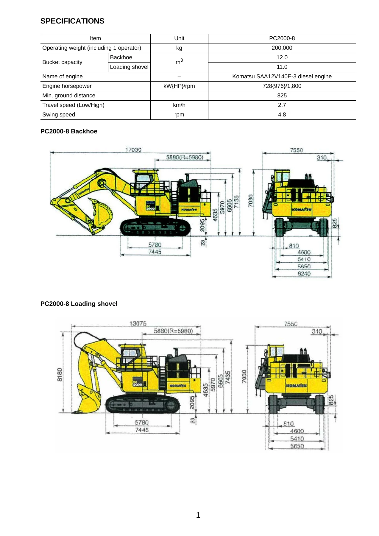
Field assembly manual for the Komatsu PC2000-8 hydraulic excavator (Backhoe and Loading Shovel) — 336 pages covering unit-by-unit assembly, slinging and transportation postures, piping and wiring connections, torque values, air bleeding, engine start-up and post-assembly inspection. Document GEN00060-16.
Description
Komatsu PC2000-8 Field Assembly Manual — GEN00060-16
The Komatsu PC2000-8 Hydraulic Excavator Field Assembly Manual (document GEN00060-16) is the document that takes the PC2000-8 from a set of shipped units back to a complete, running 200-tonne-class excavator. Because a machine of this size cannot travel on public roads in one piece, it leaves the factory divided into a center frame, left and right crawler frames, revolving frame, power container, cab base, operator’s cab, counterweight, floors, catwalks and the boom/arm/bucket group. This manual is the work instruction that tells the assembly crew how each of those units is slung, landed, coupled, piped, wired, filled and checked so the machine ends up square, sealed, correctly torqued and ready to work.
File Details
- Manual type: Field Assembly Manual
- Brand: Komatsu
- Model: PC2000-8
- Document number: GEN00060-16
- Language: English
- File format: PDF
- Page count: 336 pages
Chapters Covered
- Specifications — PC2000-8 Backhoe and PC2000-8 Loading Shovel
- Precautions for Field Assembly
- Disposal of Removed Parts
- Assembly Procedure, Assembly Equipment and Schedule
- Flowchart of Main Assembly Procedure
- Kit Layout Diagram
- Transportation Postures
- List of Parts Sent Individually
- Tools and Equipment to be Used for Local Assembly
- Tightening Torque
- Coating Materials List
- A. Assembly of Chassis
- A-1 to A-9 — Assembly of undercarriage (track frame to center frame, idler cushion cylinder piping, travel motor piping and covers, swing circle grease, revolving frame to undercarriage, swing machinery/motor, swivel joint piping, swing circle grease piping)
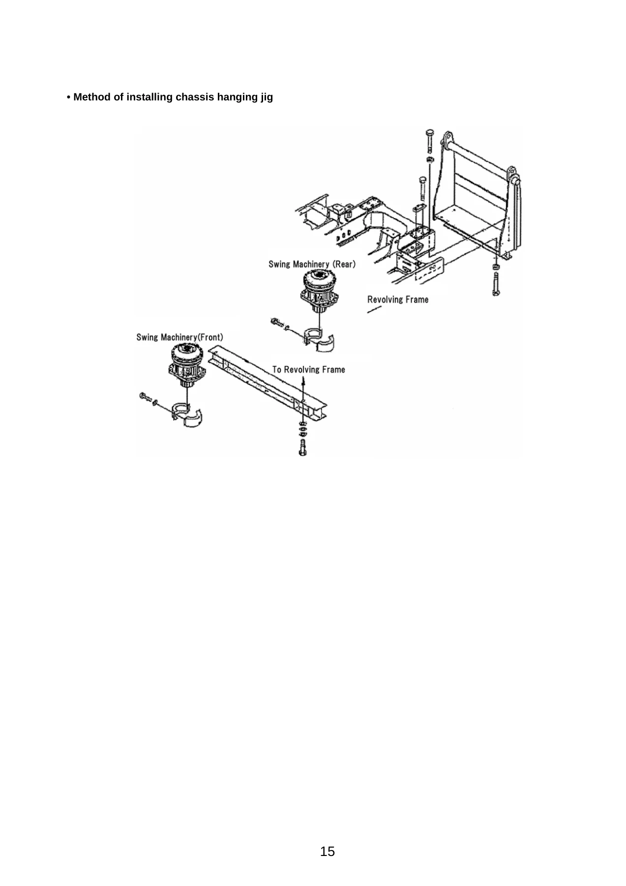
- A-10 to A-18 — Assembly of upper structure (hydraulic tank, fuel tank and piping, cab base, emergency escape ladder, left floor assembly, piping and wiring connections, heater piping)
- A-19 to A-31 — Coupling of power container (tail pipe, power container assembly, suction piping, oil cooler and pump drain piping, fan motor drain piping and piping, suction unit undercover, delivery piping, pilot and fan motor piping, fuel, air conditioner and heater piping, wiring)
- A-32 to A-41 — Operator’s cab, rotary lamp, ORBCOMM antenna, cab wiring, hydraulic piping, window washer hose, air conditioner and heater piping, cab rear floor, handrails
- A-42 to A-56 — Exterior parts and counterweight (track frame ladder, catwalk assemblies, floor assemblies, clearance adjustment, grease reel piping, access ladder, counterweight, stoppers, handrail clamps, fuel cut wire, drain piping, battery wiring)
- A-57 to A-69 — Starting the engine, checking oil and coolant, bleeding air, adjusting track, permanent tightening of swing circle bolts, touch-up, optional harnesses, rear lamps, rear camera, emergency stop switches, engine oil and PTO oil pipings, coolant piping
- C. Assembly of Backhoe
- C-1 to C-5 — Boom cylinder installation, boom cylinder hoses (Serial No. 20095 and up), boom sub assembly, boom assembly, boom cylinder head side
- C-6 to C-11 — Hoses between boom and chassis, arm assembly, arm cylinder, hoses between boom and arm, auto grease piping, wiring between boom and chassis
- C-12 to C-16 — Bucket assembly, bucket link, bleeding air from cylinders, touch-up after field assembly (work equipment side), bleeding air from auto grease circuit
- LS. Assembly of Loading Shovel Work Equipment — LS-1 to LS-17 (arm cylinder bottom parts, boom cylinder to machine body, boom cylinder hoses and piping, boom assembly, boom cylinder head pins, hose between machine body and boom, bucket cylinder assembly, arm assembly, arm cylinder assembly, hoses between boom and arm, bucket cylinder hoses, grease feed hose, bucket assembly, arm cylinder junction hoses, bottom dump hose and grease feed hose, arm dump cushion proximity switch)
- M. Inspection and Servicing Procedures After Assembly — M-1 to M-7 (oil and coolant levels, fuel and lubricant standards, hydraulic circuit flushing, releasing residual pressure, HIC circuit, air conditioner charging, mirror and light angles)
- VHMS Controller Initial Setting Procedure
- PC2000-8 Main Pump Air Bleeding Check Sheet
- Field Assembly Inspection Report (Backhoe) and Field Assembly Inspection Report (Loading Shovel)
The manual is organised so that a crew can work straight down the list. It opens with specifications, then sets out the safety and supervision structure the job requires — a work supervisor, work leader, crane director, assembly operator, mechanics, interpreter and liaison man, with the safety meeting that has to be held before assembly starts. From there it moves into the assembly sequence proper, giving for each step the slinging method, the parts involved, the tightening torque, the tools needed and the equipment required. Every assembly item carries its own parts list, so the crew can identify which bolts, washers, O-rings, seals and clips are sent loose with the kit rather than fitted at the factory. The backhoe and loading shovel work equipment are handled as separate procedures, and the manual closes with the servicing and inspection routines that have to be completed before the machine is handed over.
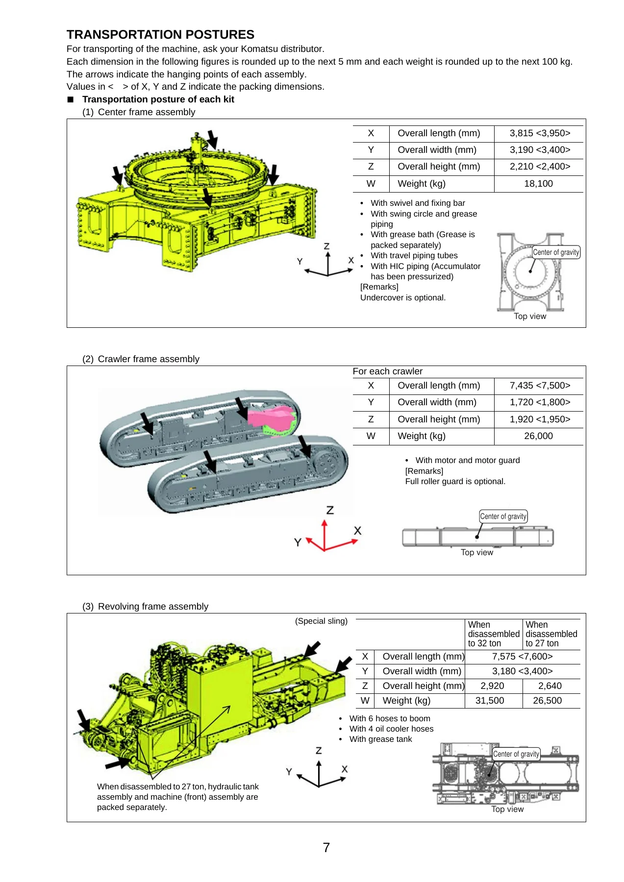
Transportation Postures and Rigging Data
One of the most useful sections for anyone planning the job is the transportation posture chapter. Each shipped kit is documented with its overall length, width and height, its packing dimensions, its weight and a top view showing the centre of gravity. The center frame assembly is listed at 18,100 kg, each crawler frame at 26,000 kg, the revolving frame at 31,500 kg (or 26,500 kg when disassembled to 27 tonnes), the power container at 16,200 kg, the counterweight at 24,500 kg, the boom at 20,950 kg, the arm at 12,950 kg and the bucket at 12,900 kg. Slinging points, wooden block placement and the precautions that go with each lift are shown directly on the drawings, which is exactly the information a crane director needs before the trailer is unloaded. The manual also gives the tools and equipment list for local assembly — crane capacities, socket sizes, taps, shackles, wire rope slings and lever blocks — so nothing has to be guessed on site.
Tightening Torques, Sealing and Coating
Bolted joints on a machine this size are not a matter of feel. The manual dedicates a chapter to tightening torque, with a general table covering M6 through M39 threads, separate tables for pipe threads in mild steel, cast iron and light alloy, and a hydraulic hose connecting nut table keyed to hose outside diameter and width across flats. Assembly steps then quote their own figures where they differ — for example the M45 x P3 track frame to center frame bolts at 4413–4903 Nm (450–500 kgm), the M42 x P3 power container and counterweight bolts at 3430–4212 Nm (350–430 kgm), and the M36 x P3 swing circle bolts at 2450–3040 Nm (250–300 kgm). The coating materials list names the adhesives, gasket sealants, molybdenum disulfide lubricants, greases, primers and caulking materials used during assembly, with their Komatsu codes, part numbers, container sizes and applications, so the correct sealant goes on the correct face.
Starting Up After Assembly
The engine start-up chapter is where the assembly job is proved out. It walks through inspecting and topping up the engine oil pan, hydraulic tank, PTO case, swing machinery case and final drive case, checking for oil leakage, bleeding air from the fuel circuit using the priming pump lever and air bleeding plug, then bleeding the hydraulic pumps, work equipment cylinder circuits, swing motor circuit, swing holding brake circuit, travel motor circuit, control valve spools and pilot selector valves. The HIC (Hydraulic Idler Cushion) circuit gets its own extended treatment — system configuration, pressure filling, air bleeding, accumulator pressure, and the track shoe tension adjustment that must be done through the grease cylinder only after the cushion cylinder has been set to its 135 ± 5 mm plunger projection. The manual explains the consequences plainly: adjust the hydraulic idler cushion defectively and excessive force goes through the undercarriage parts and they may break.
Who This Manual Is For
This is written for the people who actually do the work — field assembly supervisors, crane directors and signalmen, mechanics connecting hydraulic piping and wiring harnesses, and technicians carrying out the final inspection. It is equally useful to a service manager planning a machine delivery, because the assembly schedule, kit layout and tool lists let the job be costed and resourced before the trucks arrive. A note on scope: the manual deliberately describes the basic specification rather than the whole machine specification, and it points to the Operation and Maintenance Manual for routine servicing items. What it does cover is the complete assembly sequence for both the backhoe and the loading shovel versions of the PC2000-8.
Get the Komatsu PC2000-8 Field Assembly Manual Delivered Instantly
IMAGES PREVIEW
With this Komatsu PC2000-8 Hydraulic Excavator Field Assembly Manual on hand, a crew can plan the lifts, match the parts, apply the correct torque, seal every joint, bleed every circuit and run the post-assembly checks in the order the manufacturer intended — instead of working from memory or from a partially legible printout. Correct assembly procedure is what keeps a 200-tonne excavator structurally sound, hydraulically clean and safe to operate; getting a torque value wrong or skipping an air bleed has consequences that show up much later and cost far more to fix. The document is delivered as an instant PDF download after payment — no shipping, no waiting, viewable on a laptop, tablet or phone at the jobsite, and printable page by page so the crew can carry the sheets they need. Whether you are commissioning a PC2000-8 for the first time or re-assembling one after transport, this manual puts the full procedure in your hands.



Reviews
There are no reviews yet.