
Komatsu PC210LC-11 Shop Manual Section 40 Troubleshooting SEN06695-01 – PDF
Original price was: $39.95.$24.95Current price is: $24.95.
The complete Komatsu PC210LC-11 troubleshooting section (SEN06695-01). Full failure code diagnostics, E-Mode/H-Mode/S-Mode procedures, connector layouts, wiring diagrams, and Urea SCR system troubleshooting for the PC210LC-11 hydraulic excavator.
Description
The Komatsu PC210LC-11 Shop Manual – Section 40 Troubleshooting (SEN06695-01) is the complete troubleshooting and diagnostic reference for the Komatsu PC210LC-11 hydraulic excavator. This is the exact section a technician reaches for when a machine throws a failure code, loses power, refuses to crank, or shows any hydraulic, electrical, or engine symptom that needs a structured diagnostic path. Rather than guessing at a repair, this Komatsu PC210LC-11 troubleshooting shop manual walks through the step-by-step procedures, measurement criteria, and related circuit diagrams needed to isolate the root cause and repair it correctly the first time.
File Details
- Manual Type: Shop Manual – Section 40 Troubleshooting
- Brand: Komatsu
- Model: PC210LC-11 hydraulic excavator
- Document Number: SEN06695-01
- Language: English
- File Format: PDF
- Page Count: Approximately 400 pages
- Coverage: Troubleshooting, failure code diagnostics, electrical, hydraulic, mechanical and engine systems
What This Komatsu PC210LC-11 Troubleshooting Manual Covers
This is not a general repair guide. It is the troubleshooting and failure-code diagnostic section of the PC210LC-11 shop manual, built around the actual diagnostic logic the machine uses. Every failure code has a defined troubleshooting path with cause tables, measurement points, criteria values, and related wiring diagrams. The manual separates troubleshooting into four distinct modes so a technician can go straight to the right procedure:
- Failure Code Troubleshooting – direct diagnosis by the code shown on the machine monitor
- E-Mode – electrical system troubleshooting for symptoms without a code
- H-Mode – hydraulic and mechanical system troubleshooting
- S-Mode – engine troubleshooting
Failure Code Diagnostics
The failure codes table covers the complete range of codes for this machine, including the 879-series air conditioner codes, 989-series engine controller lock cautions, AdBlue/DEF and Urea SCR codes (AS00R2 through AS00R6 and the AdBlue/DEF level codes), engine codes (CA-series), KDPF/KDOC aftertreatment codes, pump controller codes (DA-series), hydraulic solenoid codes (DW-series), and monitor codes. Each code entry gives the failure description, the controller action, the machine-visible phenomenon, and a numbered troubleshooting table with measuring locations, criteria, and remarks.
E-Mode Electrical Troubleshooting
The E-Mode section covers 58 numbered electrical symptoms from E-1 through E-58. These include engine does not crank, preheating system faults, monitor display issues, gauge and monitor lighting problems, auto-decelerator faults, working mode selection issues, travel speed faults, swing brake cancel faults, one-touch power maximizing faults, alarm and horn faults, wiper and washer faults, monitoring function indicator faults, attachment circuit selection issues, and KOMTRAX system problems. Each symptom has its own flowchart or step table with connector references and voltage/resistance criteria.
H-Mode Hydraulic and Mechanical Troubleshooting
The H-Mode section covers 37 numbered hydraulic and mechanical symptoms from H-1 through H-37. This includes all-work-equipment failures, speed and power complaints, fine control issues, hydraulic pump noise, engine speed drop under load, individual boom/arm/bucket speed and power complaints, hydraulic drift, combined operation issues, travel problems, swing problems, and fan speed/noise issues. A system chart and failure mode/cause table provide the diagnostic framework.
S-Mode Engine Troubleshooting
The S-Mode section covers 26 numbered engine symptoms from S-1 through S-26. These range from engine does not crank, no exhaust gas, misfiring, poor startability, rough running, lack of power, KDPF clogging, oil consumption, contaminated oil, fuel consumption, coolant and oil mixing, oil pressure drop, overheating, unusual noise, vibration, air bleeding issues, active regeneration frequency and duration, white smoke during regeneration, AdBlue/DEF consumption, and foreign materials in AdBlue/DEF.
Checks Before Troubleshooting
Before any diagnostic procedure, the manual requires a set of pre-checks covering engine, lubricating oil, coolant, AdBlue/DEF, hydraulic and mechanical equipment, electrical equipment, exterior parts, and interior parts. Criteria and remedies are given for each check item, along with fuel level and type verification, impure ingredient checks, fuel prefilter inspection, water separator draining, main filter checks, engine oil level, coolant level, air cleaner clogging, hydraulic oil level and strainer checks, swing machinery case, damper case, final drive case oil levels, and air bleeding procedures for both fuel and hydraulic systems.
Connector and Wiring Reference
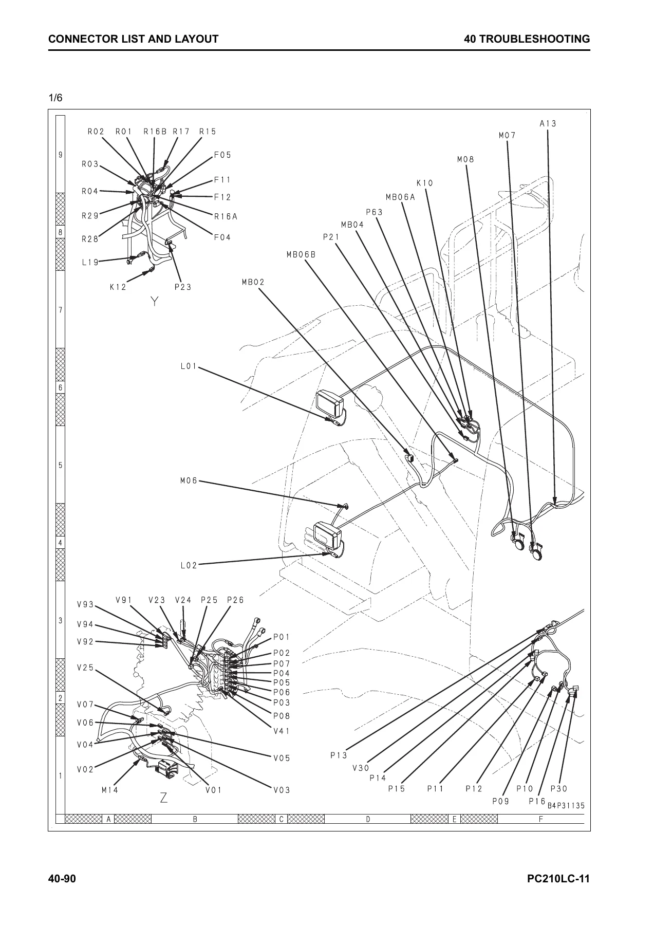
The manual includes a complete connector list and layout with address locations, connector contact identification for X-type, SWP-type, M-type, S-type, MIC-type, AMP040, AMP070, AMP/EJ2, L-type, KES, HD30 series, DT series, DTM, DTP, DRC26, DRC12/16, and engine-specific connectors (FRAMATOME, SUMITOMO, BOSCH, DELPHI, TYCO, PACKARD). The T-branch box and T-branch adapter table lists the exact part numbers needed for diagnostic testing. A fuse location table covers fuse box F01 and F02 with fuse capacities and destinations.
Urea SCR and Aftertreatment
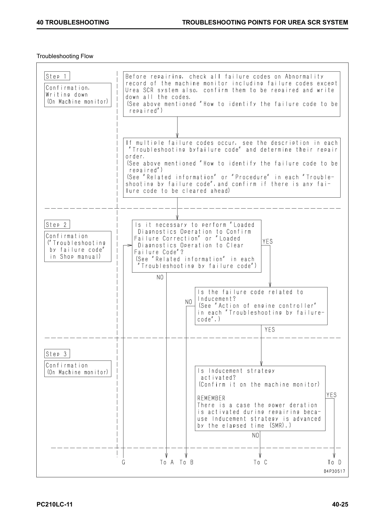
This section includes dedicated troubleshooting points for the Urea SCR system, including engine controller shutdown behavior, loaded diagnostics operation to confirm failure correction and to clear failure codes, SCR service test procedures, AdBlue/DEF level and quality checks, KDPF soot accumulation levels, manual stationary regeneration procedures, KCSF and KDOC cleaning and replacement precautions, and the full list of failure codes related to Inducement strategy that cannot be cleared at engine power deration or when AdBlue/DEF is frozen.
Chapters Covered
- Related Information on Troubleshooting
- General Troubleshooting Points
- Troubleshooting Points for Urea SCR System
- Sequence of Events in Troubleshooting
- Checks Before Troubleshooting
- Inspection Procedure Before Troubleshooting
- Walk-Around Check
- Testing in Accordance with Testing Procedure
- Check Fuel Level and Type
- Check Impure Ingredient in Fuel
- Check Fuel Prefilter
- Water Separator – Check / Drain Water and Sediment
- Method for Replacing Fuel Prefilter Cartridge
- Check Main Filter
- Check Engine Oil Level (Oil Amount in Oil Pan)
- Check Coolant Level (Reservoir Tank)
- Check Clogging of Air Cleaner
- Outer Element – Clean
- Elements – Replace
- Check Hydraulic Oil Level
- Check Hydraulic Oil Strainer
- Check Hydraulic Filter
- Check Oil Level in Swing Machinery Case
- Check Oil Level in Damper Case
- Check Oil Level in Final Drive Case
- Bleed Air from Fuel System
- Bleed Air from Hydraulic System
- Electrical Equipment – Check Method
- Electrical System Troubleshooting – Preparation
- Procedure for Testing and Troubleshooting
- Symptoms of Failure and Troubleshooting Numbers
- Information Described in Troubleshooting Table
- Troubleshooting Method for Open Circuit in Wiring Harness of Pressure Sensor System
- Connector List and Layout
- Connector Contact Identification
- T-Branch Box and T-Branch Adapter Table
- Fuse Location Table
- Precautions for Cleaning and Replacing KDPF (KCSF and KDOC)
- Preparation of Short Circuit Electrical Connector
- Failure Codes Table
- Troubleshooting by Failure Code (Display of Code)
- Troubleshooting of Electrical System (E-Mode)
- Troubleshooting for Hydraulic and Mechanical Systems (H-Mode)
- Troubleshooting of Engine (S-Mode)
Why This Troubleshooting Manual Matters
A modern Komatsu excavator like the PC210LC-11 is controlled by multiple electronic controllers – engine controller, pump controller, machine monitor, KOMTRAX terminal – and a failure can be caused by anything from a broken wire to a clogged KDPF to a worn hydraulic component. Without the correct troubleshooting procedure, a technician can spend hours chasing the wrong component. This manual gives the exact diagnostic sequence the machine was designed around, including the measurement criteria that tell you whether a sensor is actually bad or whether the wiring harness is at fault.
The wiring harness open-circuit method for pressure sensor systems is a good example: rather than simply replacing a sensor, the manual shows how to compare the sensor unit resistance against the resistance measured through the complete wiring harness, using a 10x difference threshold to determine if the harness has an open circuit. That kind of procedure prevents unnecessary parts replacement and gets the machine back to work faster.
Who This Manual Is For
This Komatsu PC210LC-11 troubleshooting section is written for professional diesel technicians, fleet maintenance managers, and owner-operators who need to diagnose and repair the machine correctly. It is also useful for anyone preparing for Komatsu-specific service training, since the failure code structure and diagnostic modes reflect how the machine actually communicates faults. The electrical and hydraulic schematics, connector pinouts, and component location diagrams make it practical for both field diagnostics and shop repair.
Get the Komatsu PC210LC-11 Shop Manual – Section 40 Troubleshooting
This manual enables you to troubleshoot every failure code the PC210LC-11 can display, work through electrical, hydraulic, mechanical, and engine symptoms systematically, and verify repairs using the exact measurement criteria the machine expects. Whether you are chasing an intermittent electrical fault, diagnosing a hydraulic drift complaint, investigating an aftertreatment regeneration issue, or trying to clear an Inducement-related failure code, the procedure is here.
IMAGES PREVIEW
Delivered as an instant PDF download. No shipping, no waiting. The file works on any device – laptop, tablet, or smartphone – and every page is printable for use in the shop or field. Take it with you on the job and stop guessing at repairs.
Reviews
There are no reviews yet.