
Komatsu PC210LCI-11 Hydraulic Excavator Shop Manual SEN06616-03 – Complete PDF Repair, Service & Troubleshooting Guide
Original price was: $39.95.$24.95Current price is: $24.95.
The complete Komatsu PC210LCI-11 Hydraulic Excavator Shop Manual (SEN06616-03) in PDF – 3,707 pages covering engine, hydraulics, ICT, SCR, electrical systems, troubleshooting, disassembly and reassembly for serial numbers 500470 and up.
Description
Komatsu PC210LCI-11 Hydraulic Excavator Shop Manual – SEN06616-03
This Komatsu PC210LCI-11 Hydraulic Excavator Shop Manual is the complete technical service publication for machines from serial number 500470 and up. Published under document number SEN06616-03, it contains 3,707 pages of detailed procedures covering every major system on the PC210LCI-11, from the SAA6D107E-3 diesel engine through the hydraulic, electrical, ICT and aftertreatment systems. Whether you are diagnosing a fault code, rebuilding a cylinder, calibrating the intelligent Machine Control system, or performing scheduled maintenance, this PC210LCI-11 shop manual provides the specifications, procedures and reference values you need in a single PDF.
File Details
- Manual type: Shop Manual (complete workshop service publication)
- Brand: Komatsu
- Model: PC210LCI-11 Hydraulic Excavator
- Document number: SEN06616-03
- Serial number coverage: 500470 and up
- Language: English
- Page count: 3,707 pages
- File format: PDF
Chapters Covered
- 00 INDEX AND FOREWORD – Abbreviation list, foreword, safety notice for operation, precautions to prevent fire, actions if fire occurs, precautions for disposing of waste materials, actions taken to meet exhaust gas regulations, precautions for DEF, precautions for handling hydraulic equipment, precautions for disconnection and connection of pipings, precautions for handling electrical equipment, fuel system equipment, intake system equipment, practical use of KOMTRAX, disconnect and connect push-pull type coupler, precautions for disconnection and connection of connectors, how to read electrical wire code, explanation of terms for maintenance standard, standard tightening torque table, conversion table
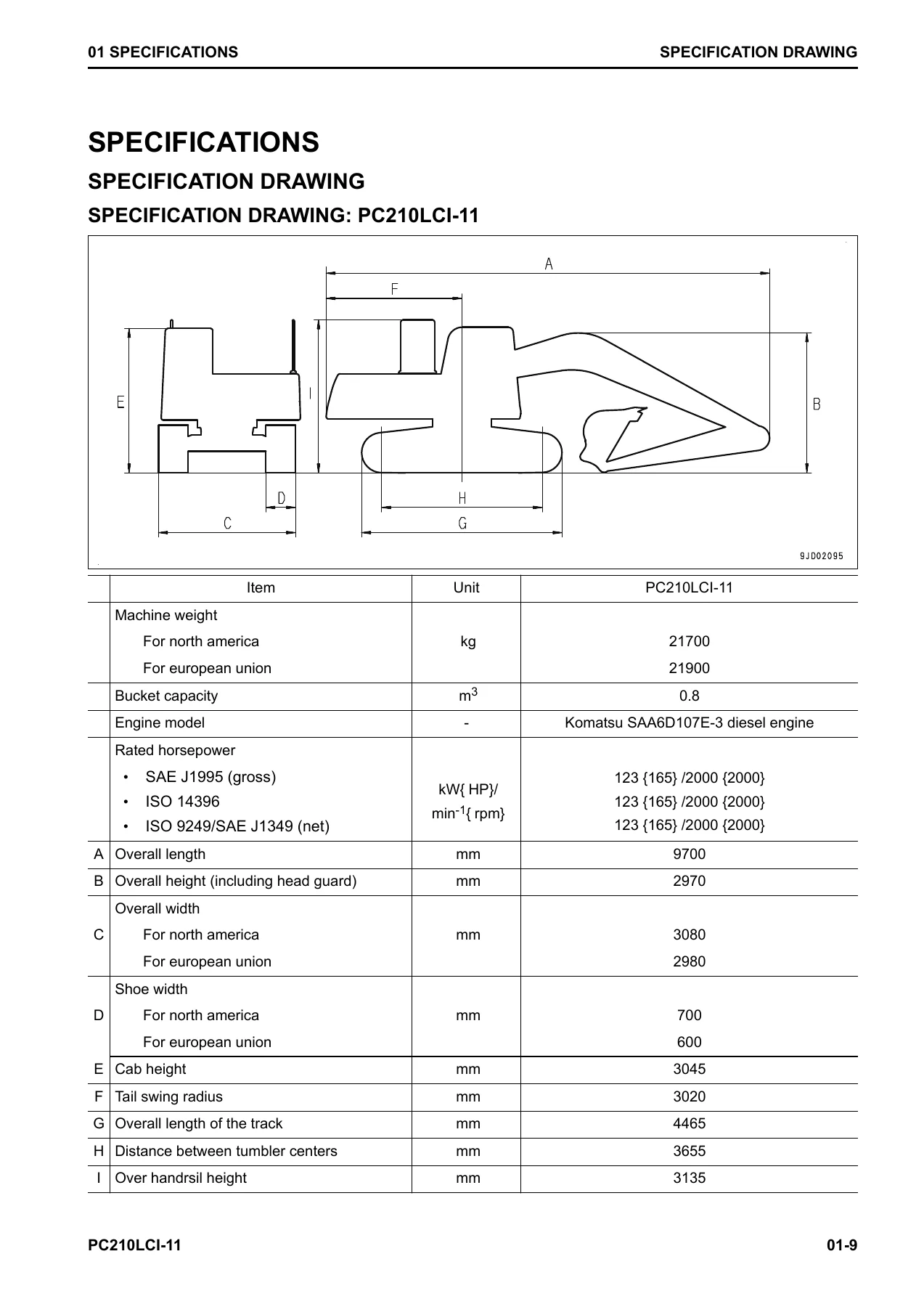
- 01 SPECIFICATIONS – Abbreviation list, specifications, specification drawing, working range drawings, weight table, table of fuel, coolant and lubricants
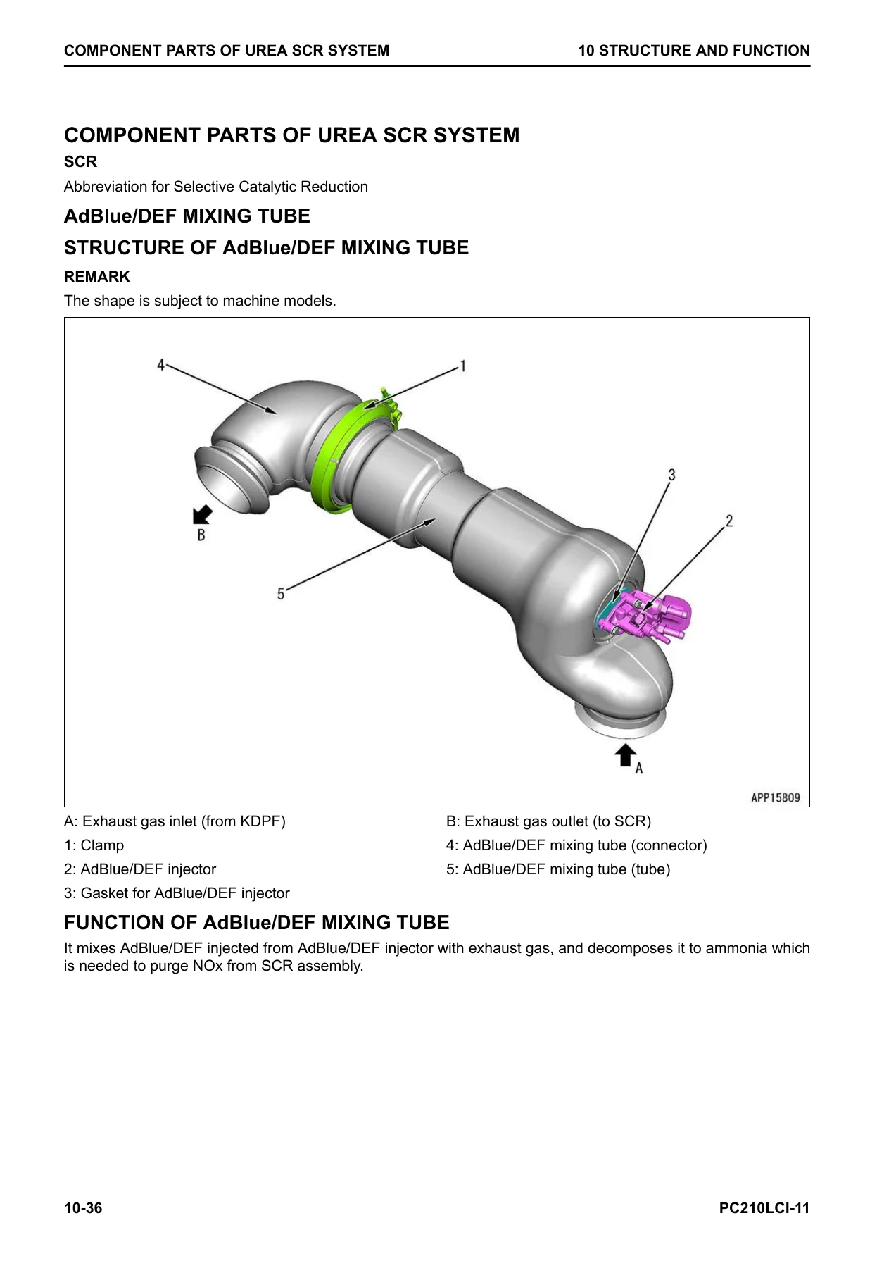
- 10 STRUCTURE AND FUNCTION – Urea SCR system, AdBlue/DEF system, inducement strategy, boot-up system, system operating lamp system, battery disconnect switch, engine system, engine control system, auto-deceleration system, engine automatic warm-up system, overheat prevention system, turbocharger protection system, automatic idle stop system, VGT, EGR system, EGR valve, EGR cooler, KCCV system, KCCV ventilator, KDPF, cooling system, fan speed control system of fan clutch, control system, machine monitor system, KomVision system, KOMTRAX system, hydraulic system, CLSS, engine and pump combined control system, pump and valve control system, work equipment system, one-touch power maximizing system, PPC lock system, work equipment and travel automatic lock system, oil flow adjuster system for attachment, ICT system, bucket edge position detection system, intelligent Machine Control system, auto grade assist control, auto stop control, cushion system for arm in end, boom secondary drive switch, swing system, travel system, undercarriage and frame, work equipment, cab and its attachments
- 20 STANDARD VALUE TABLE – Standard value table for engine, standard value table for machine, machine posture and procedure for measuring performance, standard value table for electrical
- 30 TESTING AND ADJUSTING – Tools for testing and adjusting, engine and cooling system tests, power train tests, undercarriage and frame, hydraulic system tests, electrical system setup and operation of machine monitor, ICT system calibration including PPC pressure sensor calibration, control map calibration, IMU sensor calibration, work equipment cylinder calibration, general calibration of bucket blade edge position, boom dimensions, arm dimensions, bucket link dimensions and GNSS antenna position with total station, Pm Clinic
- 40 TROUBLESHOOTING – General troubleshooting points, troubleshooting points for urea SCR system, sequence of events in troubleshooting, checks before troubleshooting, preparation for troubleshooting of electrical system, procedure for testing and troubleshooting, symptoms of failure and troubleshooting numbers, information described in troubleshooting table, connector list and layout, connector contact identification, T-branch box and T-branch adapter table, fuse location table, precautions for cleaning and replacing KDPF (KCSF and KDOC), failure codes table, troubleshooting by failure code, troubleshooting of electrical system (E-Mode), troubleshooting for hydraulic and mechanical systems (H Mode), troubleshooting of engine (S-Mode)
- 50 DISASSEMBLY AND ASSEMBLY – Related information on disassembly and assembly, coating materials list, special tools list, sketches of special tools, engine and cooling system removal and installation, hydraulic system removal and installation, swing system removal and installation, travel system removal and installation, work equipment removal and installation, cab and its attachments removal and installation
- 60 MAINTENANCE STANDARD – Maintenance standard of engine, maintenance standard of hydraulic system, maintenance standard of swing system, maintenance standard of travel system, maintenance standard of work equipment, maintenance standard of electrical system
- 80 APPENDIX – Air conditioner system, precautions for refrigerant, air conditioner component, specifications of air conditioner, configuration and function of refrigeration cycle, outline of refrigeration cycle, component parts of air conditioner system, air conditioner unit, air conditioner controller, compressor, condenser, sensors for air conditioner system, explanation of procedure for testing and troubleshooting of air conditioner, circuit diagram and arrangement of connector pins for air conditioner, air conditioner system diagram, input and output signals of air conditioner controller, installation locations of air conditioner parts and arrangement of connectors, testing air leakage (duct), testing air conditioner using self-diagnosis function, test vent (mode) changeover, testing fresh/recirc air changeover, test sunlight sensor, test (dual) pressure switch for refrigerant, test relays, air conditioner troubleshooting chart, troubleshooting for power supply system, troubleshooting for compressor and refrigerant system, troubleshooting for blower motor system, troubleshooting for fresh/recirc air changeover, troubleshooting using gauge pressure, connection of service tool, precautions for disconnecting and connecting hoses and tubes in air conditioner pipings, handle compressor oil, method for replacing desiccant
- 90 CIRCUIT DIAGRAMS – Hydraulic circuit diagram symbols, hydraulic circuit diagram (1/2 and 2/2), electrical circuit diagram symbols, electrical circuit diagram (1/12 through 12/12), electrical circuit diagram (1/13 through 11/13)
This Komatsu PC210LCI-11 shop manual is not a generic repair guide. It is the document Komatsu service technicians use, covering the intelligent Machine Control system, the urea SCR aftertreatment system, the CLSS hydraulic system with engine and pump combined control, and the full electrical architecture of the PC210LCI-11. The structure moves from understanding the machine (Structure and Function) through measuring and testing (Standard Value Table, Testing and Adjusting) to diagnosing faults (Troubleshooting), removing and rebuilding components (Disassembly and Assembly) and checking wear against limits (Maintenance Standard). For any technician working on a PC210LCI-11 from serial 500470 onward, this manual provides the correct procedures, tightening torques, pressures, clearances and calibration routines without guesswork.
Why This PC210LCI-11 Shop Manual Matters
The PC210LCI-11 combines a conventional hydraulic excavator platform with an intelligent Machine Control system that uses GNSS, IMU sensors, stroke-sensing cylinders and EPC valves to control the work equipment automatically. Servicing this machine without the correct calibration procedures, failure code definitions and hydraulic circuit diagrams is not practical. This PC210LCI-11 repair manual gives you the complete failure code table with troubleshooting procedures, the wiring and hydraulic circuit diagrams needed to trace faults, and the step-by-step calibration routines for the auto grade assist and auto stop control functions.
The engine side is equally detailed. The SAA6D107E-3 engine section covers the common rail fuel injection system, VGT, EGR, KCCV, KDPF and the urea SCR system, with testing and adjusting procedures for boost pressure, fuel pressure, compression pressure, blowby pressure, valve clearance and exhaust gas colour. The troubleshooting section separates engine faults (S-Mode), electrical faults (E-Mode) and hydraulic or mechanical faults (H-Mode), so you can approach a problem systematically rather than replacing parts at random.
What You Can Do With This Manual
- Read and clear failure codes on the machine monitor, then follow the correct troubleshooting procedure for each code.
- Test and adjust hydraulic pressures in the work equipment, swing, travel, PC control and LS control circuits.
- Calibrate the intelligent Machine Control system, including PPC pressure sensors, control maps, IMU sensor, work equipment cylinders and GNSS antenna position.
- Remove and install the engine, main pump, control valve, swing motor, travel motor, cylinders and undercarriage components.
- Disassemble and assemble the urea SCR system, KDPF, AdBlue/DEF pump and injector.
- Diagnose and repair the air conditioner system using the self-diagnosis function and troubleshooting charts.
- Check wear against maintenance standards and decide whether to repair or replace components.
- Perform Pm Clinic inspections with the check sheets and standard value tables.
Delivery
IMAGES PREVIEW
This Komatsu PC210LCI-11 Hydraulic Excavator Shop Manual is delivered as an instant PDF download after payment. There is no shipping, no waiting for a physical book, and no restrictions on where you use it. Open it on a laptop in the workshop, a tablet in the cab, or print the pages you need for the job at hand. The PDF format keeps all 3,707 pages searchable and navigable so you can move between the contents, failure code tables, circuit diagrams and procedures quickly. For anyone maintaining, repairing or owning a PC210LCI-11, this manual is the reference that makes correct repair possible.
Reviews
There are no reviews yet.