
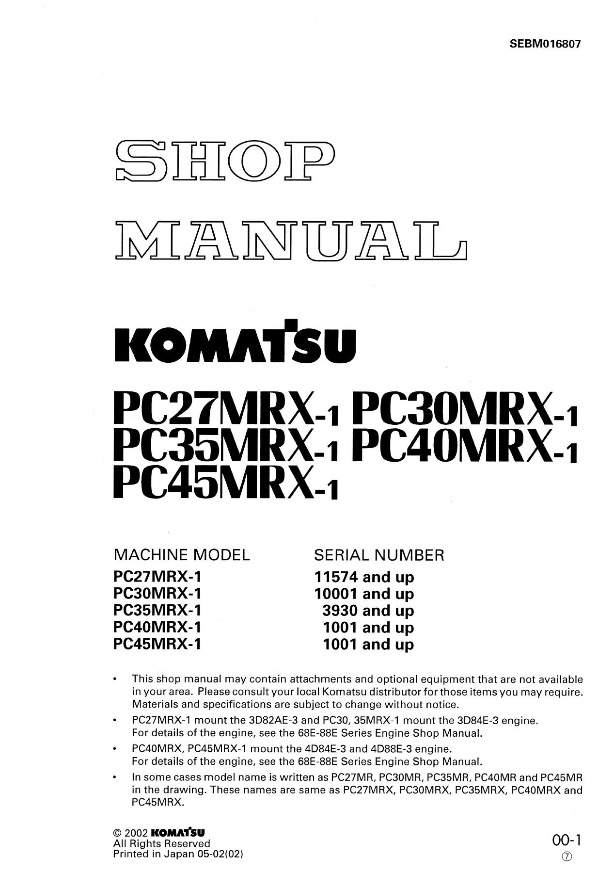
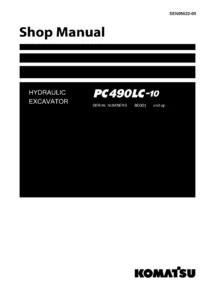
Komatsu PC27MRX-1 PC30MRX-1 PC35MRX-1 PC40MRX-1 PC45MRX-1 Shop Manual PDF
Original price was: $44.95.$26.95Current price is: $26.95.
946-page Komatsu shop manual covering PC27MRX-1, PC30MRX-1, PC35MRX-1, PC40MRX-1 and PC45MRX-1 machines, with specifications, system operation, testing and adjusting, troubleshooting, disassembly and assembly, maintenance standards, and hydraulic/electrical diagrams.
Description
Komatsu PC27MRX-1 PC30MRX-1 PC35MRX-1 PC40MRX-1 PC45MRX-1 Shop Manual PDF
The Komatsu PC27MRX-1 PC30MRX-1 PC35MRX-1 PC40MRX-1 PC45MRX-1 Shop Manual PDF is a detailed repair and service reference covering five MRX-1 machine models. Its 946 pages combine machine specifications, system descriptions, testing and adjustment procedures, troubleshooting information, component removal and installation, disassembly and assembly procedures, maintenance standards, and hydraulic and electrical information. The manual is arranged around the way service work is actually carried out, moving from understanding each system to checking performance, locating faults, repairing components, and judging whether parts remain within usable limits.
File Details
- Manual type: Shop Manual
- Brand: Komatsu
- Models: PC27MRX-1, PC30MRX-1, PC35MRX-1, PC40MRX-1, PC45MRX-1
- Language: English
- Pages: 946
- File format: PDF
- Document number: SEBM016807
- Publication: © 2002 Komatsu; printed in Japan 06-02(02)
Model and Serial Number Coverage
This shop manual identifies the applicable machines by model and starting serial number, helping you match the repair information to the machine before beginning service work.
- PC27MRX-1: serial number 11574 and up
- PC30MRX-1: serial number 10001 and up
- PC35MRX-1: serial number 3930 and up
- PC40MRX-1: serial number 1001 and up
- PC45MRX-1: serial number 1001 and up
The manual also distinguishes model-specific arrangements and serial-number changes inside individual sections. Examples include separate canopy and cab specifications, different hydraulic layouts, and revised arrangements for later PC40MRX-1 and PC45MRX-1 serial ranges.
What This Manual Helps You Service
The manual goes well beyond basic maintenance. It explains how major machine systems are built and how they operate, then connects that information to measurable service data and repair procedures. Detailed drawings show assemblies and fluid circuits, while testing sections give conditions for checking engine speed, hydraulic pressures, travel and swing performance, leakage, drift, control pressure, and other operating values.
Engine-related information includes engine control, radiator and oil cooler arrangements, starting and charging components, fuel injection work, valve clearance, compression pressure, engine oil pressure, fuel injection timing, fan belt tension, and fuel control adjustment. The manual identifies the 3D82AE-3, 3D84E-3, 4D84E-3 and 4D88E-3 engine families in its model coverage and directs engine-specific work according to the applicable machine.
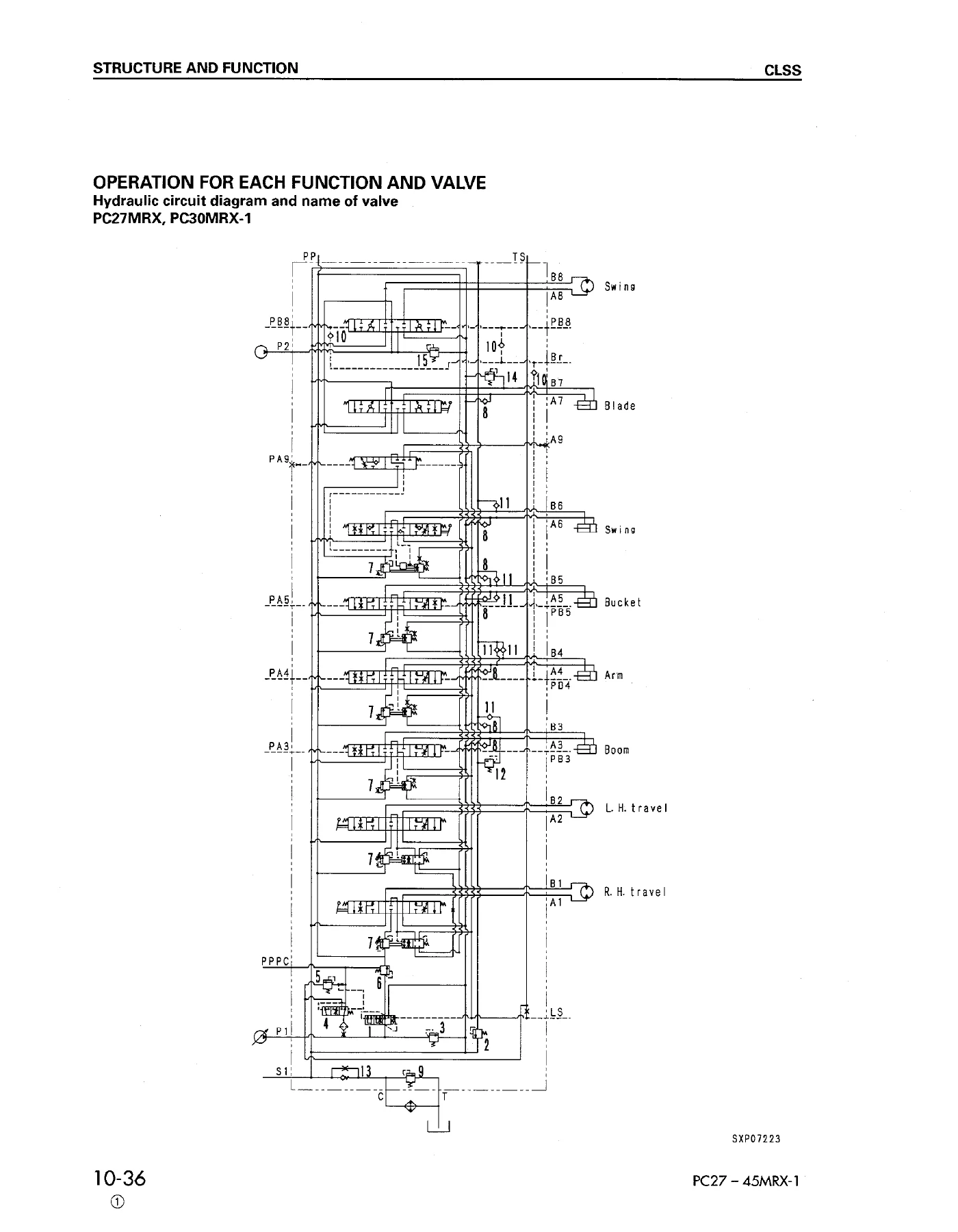
Hydraulic coverage is especially extensive. The Komatsu PC27MRX-1 PC30MRX-1 PC35MRX-1 PC40MRX-1 PC45MRX-1 Shop Manual PDF describes hydraulic piping, tanks, pumps, control valves, PPC valves, swing and travel motors, center swivel joints, cylinders, pressure compensation and the CLSS closed-center load sensing system. Circuit diagrams and functional explanations show how pump discharge, LS pressure, control valves and actuators interact during individual and combined operations.
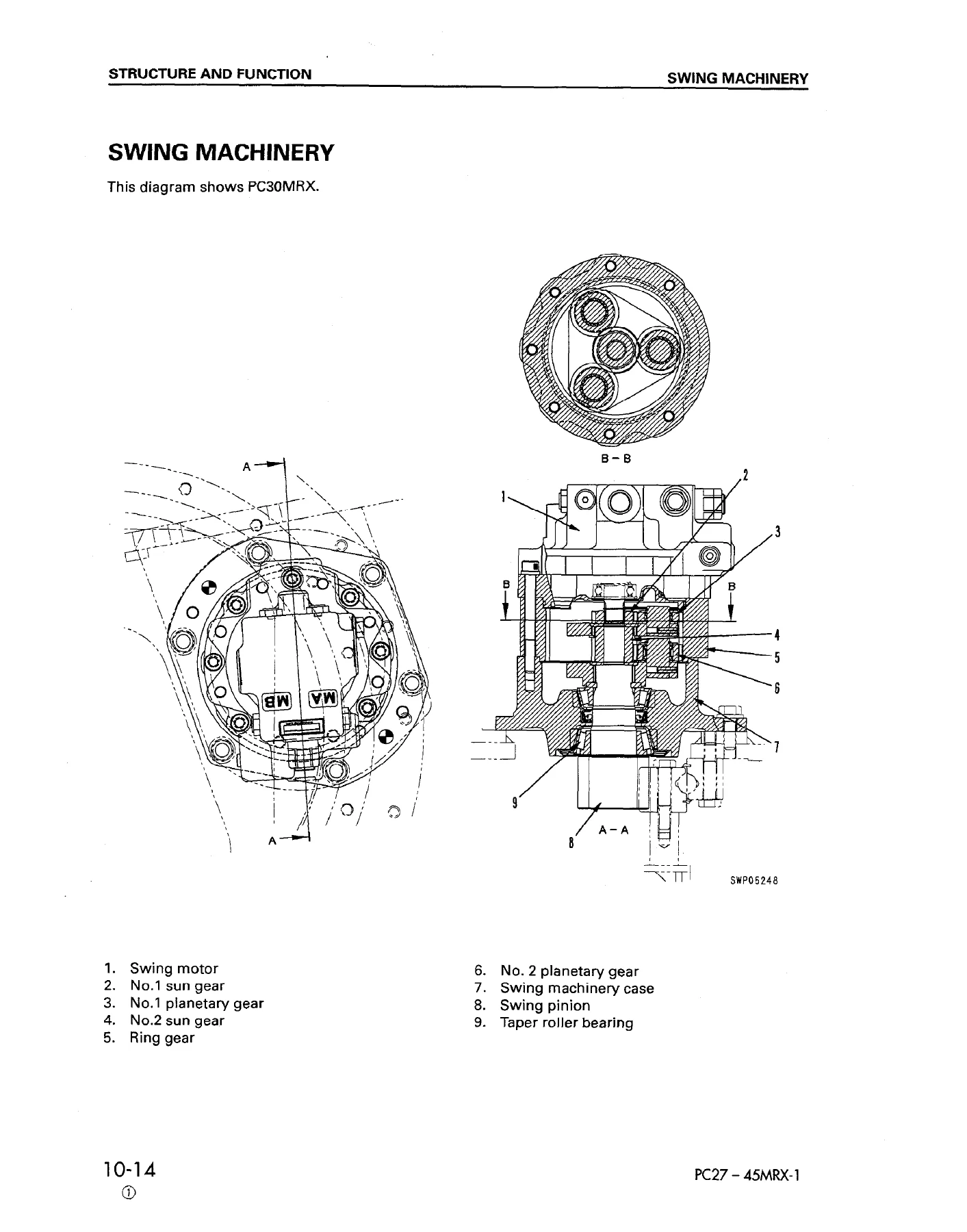
The undercarriage and rotating structure are covered through sections on the track frame, idler cushion, carrier and track rollers, sprocket, swing circle, swing machinery and travel motors. Work equipment coverage includes the boom, arm, bucket, boom swing and blade systems, together with their cylinders and controls. Electrical material includes actual wiring diagrams, connector information, machine monitor functions, sensors, solenoid valves and troubleshooting procedures for electrical faults.
Chapters Covered
- 01 General
- General assembly drawings
- Specifications
- Weight tables
- List of lubricant and water
- 10 Structure and Function
- Engine control and PTO
- Radiator and oil cooler
- Power train
- Swing circle and swing machinery
- Track frame and idler cushion
- Hydraulic piping and hydraulic tank
- CLSS closed-center load sensing system
- Hydraulic pump, LS/PC valve and servo piston
- Solenoid valve and control valve
- Swing motor, center swivel joint and travel motor
- PPC valve and service PPC valve
- Work equipment and air conditioner
- Actual electrical wiring diagrams
- Machine monitor system
- 20 Testing and Adjusting
- Standard value tables for engine and chassis related parts
- Tools for testing, adjusting and troubleshooting
- Engine speed, exhaust color, valve clearance and compression pressure
- Engine oil pressure, fuel injection timing and fan belt tension
- Fuel control lever, sprocket wear and track shoe tension
- Hydraulic control lever and pedal adjustment
- Work equipment, swing and travel hydraulic pressure
- LS differential pressure and PC valve checks
- Control circuit, solenoid valve and PPC valve pressure tests
- Swing holding brake and travel deviation checks
- Work equipment cylinder internal leakage
- Hydraulic circuit pressure release, tank pressure and air bleeding
- Hydraulic breaker service valve and nitrogen gas pressure
- Electrical diode checks
- Electrical, hydraulic/mechanical and machine monitor troubleshooting
- 30 Disassembly and Assembly
- Special tools and operating precautions
- Starting motor and alternator
- Fuel injection pump and nozzle holder
- Water pump, thermostat and engine seals
- Cylinder head, radiator and hydraulic cooler
- Engine, main pump and damper
- Center swivel joint and travel motor
- Sprocket, swing motor and swing machinery
- Revolving frame and swing circle
- Idler, recoil spring, track roller and carrier roller
- Rubber shoe, hydraulic tank and fuel tank
- Main pump and model-specific hydraulic pump procedures
- 40 Maintenance Standard
- Inspection criteria and repair limits for disassembled components
- Idler, carrier roller and track roller standards
- Sprocket and track shoe wear criteria
- Dimensional, clearance and service-limit checks used to judge reuse, repair or replacement
- 90 Others
- Hydraulic circuit diagrams
- Electrical circuit diagrams
- Specifications and information for applicable attachments and options
Taken together, these chapters provide a complete service path: identify the machine and its specifications, understand how the system functions, compare measured performance with standard values, trace symptoms through troubleshooting charts, remove and repair the affected assembly, then inspect parts against maintenance standards before reassembly.
Specifications, Service Data and Adjustment References
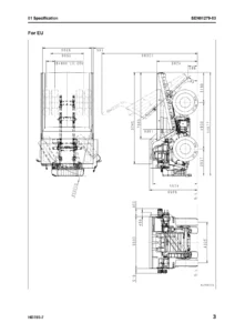
The General chapter provides model-by-model operating weights, bucket capacities, digging and reach dimensions, swing and travel figures, ground pressure, overall dimensions, engine specifications, electrical equipment, undercarriage data, hydraulic pump and motor information, cylinder dimensions, component weights, and lubricant and coolant data. These pages are useful when confirming configuration or checking whether a measurement belongs to the correct model.
Testing and Adjusting adds service values under defined conditions. Procedures cover measurements such as engine speed, compression, oil pressure, hydraulic relief pressure, LS differential pressure, control circuit pressure, swing performance, travel speed and deviation, hydraulic drift, work equipment speed and internal leakage. The manual repeatedly specifies test conditions such as hydraulic oil temperature, engine throttle position and actuator position so measurements can be compared consistently with the stated values.
Troubleshooting and Circuit Diagnosis
A large troubleshooting section explains how to confirm symptoms before unnecessary disassembly. It includes checks before troubleshooting, connector types and mounting locations, connector pin information, and dedicated troubleshooting paths for the electrical system, hydraulic and mechanical systems, and the machine monitor system. The manual also explains safe handling of wiring harnesses, connectors, control boxes and hydraulic equipment, including precautions against contamination and incorrect connector handling.
For hydraulic diagnosis, system explanations are tied to actual circuit operation. CLSS sections describe pump swash-plate control, LS differential pressure, pressure compensation, unload and relief functions, travel junction circuits and combined actuator operation. This is valuable when a symptom involves more than one component because the manual shows how valves, pumps, pressure signals and actuators influence each other.
Repair and Component Overhaul Coverage
The Disassembly and Assembly chapter supplies step-by-step removal, installation, disassembly and assembly instructions for many serviceable components. Procedures include required safety steps, pressure-release instructions, lifting information where applicable, tightening values, seal and coating notes, refill instructions and post-installation checks. Coverage extends from engine-mounted components and cooling parts to pumps, motors, swivel joints, swing machinery, undercarriage components, tanks and work equipment-related assemblies.
Maintenance Standard then supports repair decisions with dimensions, clearances, wear limits and repair criteria. Instead of relying only on visual judgement, a technician can compare measured parts with the manual’s stated standards to decide whether an item can continue in service, needs repair, or should be replaced.
Workshop Reference for the MRX-1 Range
This Komatsu PC27MRX-1 through PC45MRX-1 shop manual is particularly useful when the job requires both a procedure and the supporting technical context. A hydraulic pressure problem, for example, can be followed from structure and function diagrams to standard values, test procedures, valve adjustment information, component removal and internal inspection standards. The same approach applies to swing, travel, work equipment, engine controls and electrical diagnosis.
Get the Complete Shop Manual in PDF
Use the Komatsu PC27MRX-1 PC30MRX-1 PC35MRX-1 PC40MRX-1 PC45MRX-1 Shop Manual PDF for systematic diagnosis, adjustment, component removal and installation, hydraulic and electrical troubleshooting, and repair work backed by the procedures, specifications and service limits printed for these models. Having the correct reference matters when checking pressures, clearances, tightening values, circuit operation and component condition, because the repair can be carried out against documented procedures instead of guesswork. Your purchase is delivered as an instant PDF download after payment, with no physical shipping required. You can open it on compatible phones, tablets and computers, keep it available in the workshop, and print the pages you need for the job.

Reviews
There are no reviews yet.