
Komatsu PC300-8 PC300LC-8 PC350-8 PC350LC-8 Shop Manual 2007
Original price was: $49.95.$29.95Current price is: $29.95.
Complete 989-page Komatsu shop manual for PC300-8, PC300LC-8, PC350-8, and PC350LC-8 hydraulic excavators (serial numbers 60001 and up). Covers the SAA6D114E engine, hydraulics, electrical systems, troubleshooting, testing and adjusting, and full disassembly/assembly procedures.
Description
Komatsu PC300-8, PC300LC-8, PC350-8, PC350LC-8 Shop Manual — Complete 2007 Service Documentation
This Komatsu PC300-8 PC300LC-8 PC350-8 PC350LC-8 Shop Manual is the complete service and repair documentation for these hydraulic excavators, covering serial numbers 60001 and up. At 989 pages, it gives technicians, mechanics, and equipment owners the full manufacturer procedure set for engine, hydraulic, electrical, power train, undercarriage, work equipment, and cab systems. The manual is structured for practical workshop use, moving from specifications and structure through testing, troubleshooting, and component-level disassembly and assembly.
The Komatsu PC300-8 PC300LC-8 PC350-8 PC350LC-8 Shop Manual covers the SAA6D114E engine — a 4-cycle, water-cooled in-line, direct injection unit with turbocharger and air-cooled aftercooler — and documents the HPV125+125 variable displacement piston pump, the CLSS load sensing system, control valve operation, travel and swing motors, final drives, and the full electrical control architecture including machine monitor, engine controller, pump controller, and KOMTRAX terminal system.
File Details
- Manual Type: Shop Manual
- Brand: Komatsu
- Models Covered: PC300-8, PC300LC-8, PC350-8, PC350LC-8
- Serial Numbers: 60001 and up
- Engine: SAA6D114E
- Language: English
- Page Count: 989
- File Format: PDF
- Publication Date: 2007
Chapters Covered in This Komatsu Excavator Shop Manual
The manual follows the Komatsu shop manual structure, divided into major sections each containing detailed subsections for every serviceable system.
- 00 Index and Foreword — Safety notice, how to read the shop manual, explanation of terms for maintenance standard, handling of electric equipment and hydraulic components, handling of connectors newly used for engines, how to read electric wire code, precautions when carrying out operation, method of disassembling and connecting push-pull type coupler, standard tightening torque table, conversion table
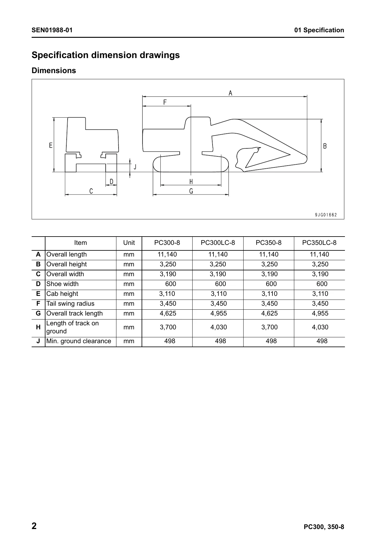
- 01 Specification — Specification dimension drawings, dimensions, working ranges, specifications, weight table, table of fuel, coolant and lubricants
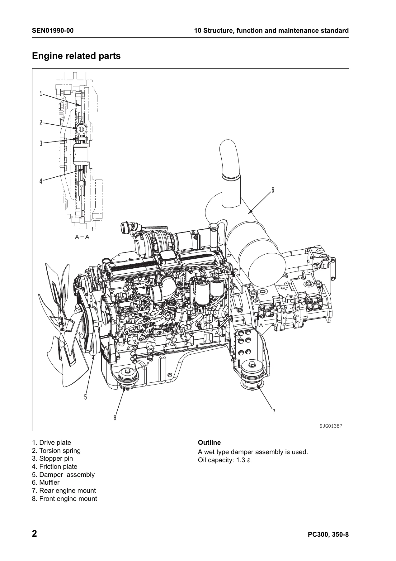
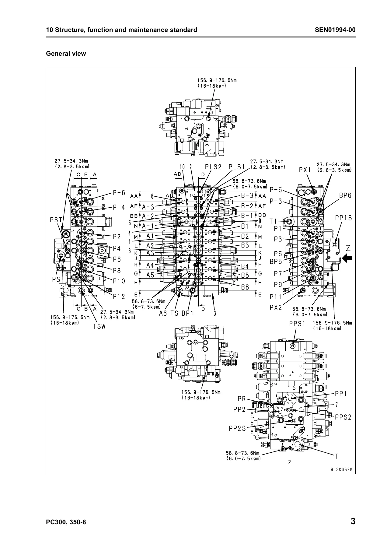
- 10 Structure, Function and Maintenance Standard — Engine and cooling system (engine related parts, radiator, oil cooler and aftercooler), Power train (power train, swing circle, swing machinery, final drive, sprocket), Undercarriage and frame (track frame and recoil spring, idler, carrier roller, track roller, track shoe), Hydraulic system Part 1 (hydraulic equipment layout drawing, hydraulic tank and filter, hydraulic pump), Hydraulic system Part 2 (control valve, CLSS, outline of CLSS, basic principle, functions and operation by valve, hydraulic circuit diagram and the name of valves, unload valve), Hydraulic system Part 3 (PPC valve, travel PPC valve, service PPC valve, solenoid valve, PPC accumulator, return oil filter, center swivel joint, travel motor, swing motor, swing holding brake, hydraulic cylinder), Work equipment, Cab and its attachments, Electrical system (engine control, electronic control system, monitor system, sensor, KOMTRAX terminal system)
- 20 Standard Value Table — Standard value table for engine related parts, standard value table for chassis related parts
- 30 Testing and Adjusting — Tools for testing, adjusting and troubleshooting, measuring engine speed, measuring air boost pressure, measuring exhaust gas color, adjusting valve clearance, measuring compression pressure, measuring blow-by pressure, measuring engine oil pressure, measuring fuel pressure, handling during cylinder cut-out operation, handling during no injection cranking operation, measuring fuel return rate and leakage, bleeding air from fuel circuit, checking fuel circuit for leakage, testing and adjusting air compressor belt tension, measuring clearance in swing circle bearings, testing and adjusting track shoe tension, testing and adjusting oil pressure in work equipment, swing and travel circuit, testing and adjusting control circuit oil pressure, testing and adjusting pump PC control circuit oil pressure, testing and adjusting pump LS control circuit oil pressure, measuring solenoid valve output pressure, measuring PPC valve output pressure, adjusting play of work equipment and swing PPC valves, inspecting locations of hydraulic drift of work equipment, releasing remaining pressure in hydraulic circuit, measuring oil leakage amount, bleeding air from various parts, diode inspection procedures, special functions of machine monitor, handling voltage circuit of engine controller, preparation work for troubleshooting of electrical system, procedure for testing diodes, Pm clinic service
- 40 Troubleshooting — Failure code table and fuse locations, general information on troubleshooting, troubleshooting by failure code (Part 1, Part 2, Part 3), troubleshooting of electrical system (E-mode), troubleshooting of hydraulic and mechanical system (H-mode), troubleshooting of engine (S-mode)
- 50 Disassembly and Assembly — General information on disassembly and assembly, how to read this manual, coating materials list, special tools list, sketches of special tools, Engine and cooling system (removal and installation of fuel supply pump assembly, engine front seal, engine rear seal, cylinder head assembly, radiator assembly, hydraulic oil cooler assembly, aftercooler assembly, engine and hydraulic pump assembly), Power train (removal and installation of final drive assembly, disassembly and assembly of final drive assembly, removal and installation of swing motor and swing machinery assembly, disassembly and assembly of swing motor and swing machinery assembly, removal and installation of swing circle assembly), Undercarriage and frame (disassembly and assembly of carrier roller, track roller assembly, idler assembly, recoil spring, removal and installation of sprocket, expansion and installation of track shoe assembly, removal and installation of revolving frame assembly, counterweight assembly), Hydraulic system (removal and installation of center swivel joint assembly, disassembly and assembly of center swivel joint assembly, removal and installation of hydraulic tank assembly, removal and installation of control valve assembly, disassembly and assembly of control valve assembly, removal and installation of hydraulic pump assembly, removal and installation of oil seal in hydraulic pump input shaft, disassembly and assembly of work equipment PPC valve assembly, travel PPC valve assembly, hydraulic cylinder assembly), Work equipment, Cab and its attachments, Electrical system
- 90 Diagrams and Drawings — Hydraulic circuit diagram, electrical circuit diagram, connector arrangement diagram
This Komatsu PC300-8 PC300LC-8 PC350-8 PC350LC-8 Shop Manual provides the full range of technical information needed for professional service work. The structure follows Komatsu’s shop manual format, with each section building on the last: specifications establish the baseline, structure and function explains how systems operate, standard values and testing procedures let you verify condition, troubleshooting helps isolate faults, and disassembly/assembly provides the procedures for component removal and installation.
For the SAA6D114E engine, the manual includes valve clearance adjustment, compression pressure testing, blow-by measurement, fuel pressure testing, fuel return rate and leakage measurement, and procedures for bleeding the fuel circuit. The hydraulic system coverage spans the HPV125+125 variable displacement piston pump, the CLSS (Closed center Load Sensing System), control valve operation, LS and PC valve function, and the travel and swing motors. Electrical troubleshooting covers the machine monitor, engine controller, pump controller, and KOMTRAX system, with failure code tables and connector pin number references.
The testing and adjusting section alone provides procedures for measuring engine speed, air boost pressure, exhaust gas color, compression pressure, blow-by pressure, engine oil pressure, and fuel pressure. It also covers hydraulic circuit testing: work equipment, swing and travel relief pressures, control circuit oil pressure, pump PC and LS control circuit oil pressure, solenoid valve output pressure, and PPC valve output pressure. Each procedure gives the standard values needed for judgement.
For major repair work, the disassembly and assembly section covers removal and installation of the engine and hydraulic pump assembly, cylinder head assembly, final drive, swing motor and swing machinery, center swivel joint, control valve, hydraulic pump, hydraulic cylinders, and work equipment. Torque values, coating materials, and special tool requirements are listed for each procedure.
What This Komatsu Shop Manual Enables You to Do
With this manual, you can perform the full range of service and repair operations on PC300-8, PC300LC-8, PC350-8, and PC350LC-8 excavators. That includes routine maintenance items like oil changes, filter replacements, valve clearance adjustments, and track tension checks. It includes diagnostic work using failure codes, monitoring functions, and electrical circuit testing. It includes hydraulic system testing and adjustment, from relief pressures to pump control circuits. And it includes major component removal, disassembly, assembly, and installation for the engine, hydraulic pump, control valve, travel and swing motors, final drives, cylinders, and work equipment.
Having the correct procedures and specifications matters because these machines operate under high pressure and heavy loads. Incorrect relief pressure settings, improper torque values, or missed adjustment steps can lead to component damage, poor performance, or unsafe operation. The Komatsu PC300-8 PC300LC-8 PC350-8 PC350LC-8 Shop Manual gives you the exact numbers and sequences the manufacturer specifies.
IMAGES PREVIEW
This manual is delivered as an instant PDF download after payment. No shipping, no waiting for a physical book. You can view it on any device — laptop, tablet, or smartphone — and print the pages you need for the job at hand. Keep the complete manual on hand for reference in the workshop, or print only the section you are working on.
Reviews
There are no reviews yet.