
Komatsu PC360LC-10 Hydraulic Excavator Shop Manual SEN05619-03 – Complete PDF Service & Repair Guide
Original price was: $59.95.$39.95Current price is: $39.95.
Complete Komatsu PC360LC-10 shop manual SEN05619-03 in PDF. Full factory service, repair, hydraulic, electrical and troubleshooting coverage for serial 70001 and up – instant download.
Description
This Komatsu PC360LC-10 shop manual is the complete PDF service and repair reference for the PC360LC-10 hydraulic excavator, serial number 70001 and up. Published under document number SEN05619-03, the manual covers the Komatsu SAA6D114E-5 diesel engine, the CLSS hydraulic system, swing and travel components, undercarriage, work equipment, and the full electrical control and monitor architecture. Every major repair, diagnostic procedure, torque value and service limit for the machine is documented in a single file, making this the most complete Komatsu PC360LC-10 service manual available as an instant PDF download.
File Details
- Manual Type: Shop Manual
- Brand: Komatsu
- Model: PC360LC-10
- Serial Number: 70001 and up
- Engine: Komatsu SAA6D114E-5
- Language: English
- Page Count: 1,726
- File Format: PDF
- Document Number: SEN05619-03
- Publication Date: 03-13 (March 2013)
Chapters Covered
- 00 Index and foreword
- 01 Specification
- 10 Structure and function
- 20 Standard value tables
- 30 Testing and adjusting
- 40 Troubleshooting
- 50 Disassembly and assembly
- 60 Maintenance standard
- 80 Appendix
- 90 Diagrams and drawings
Specification and Model Data
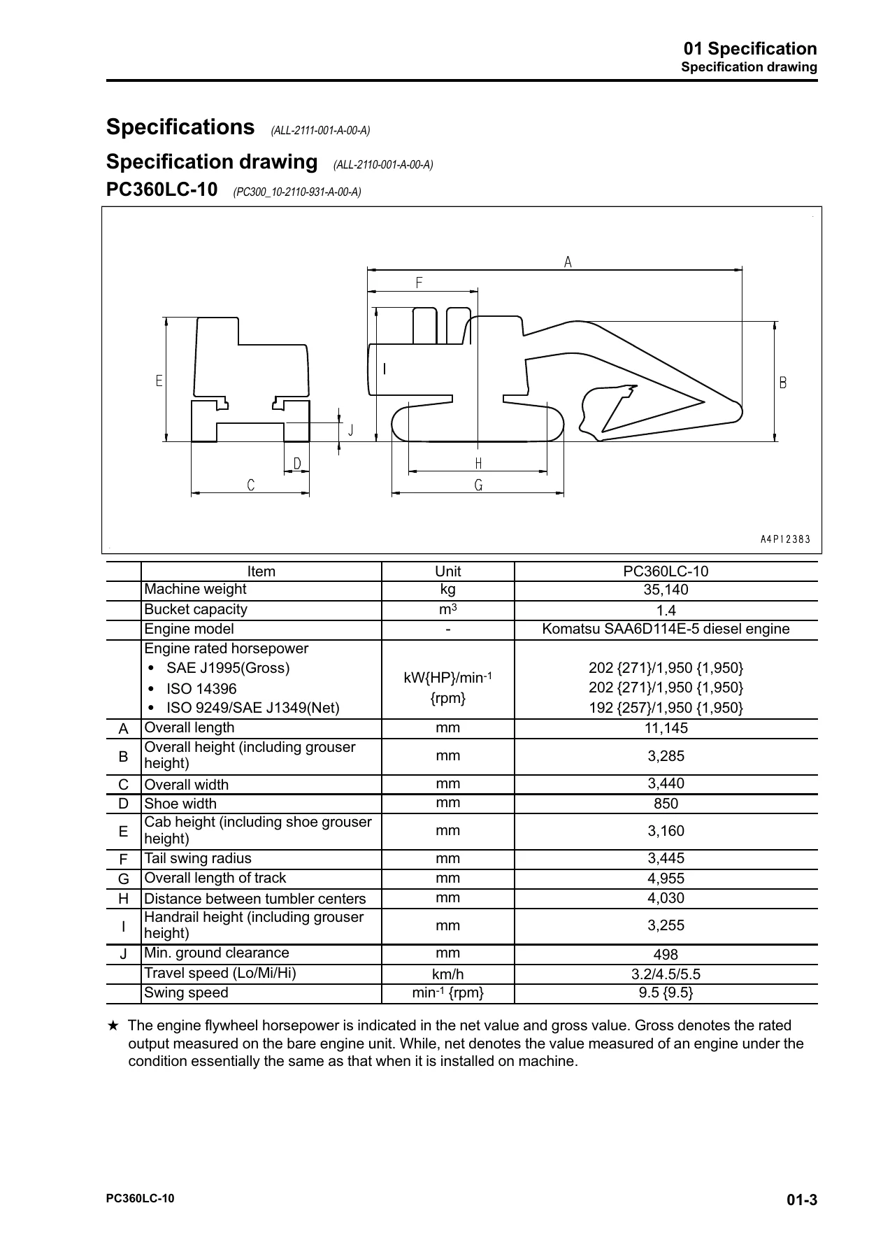
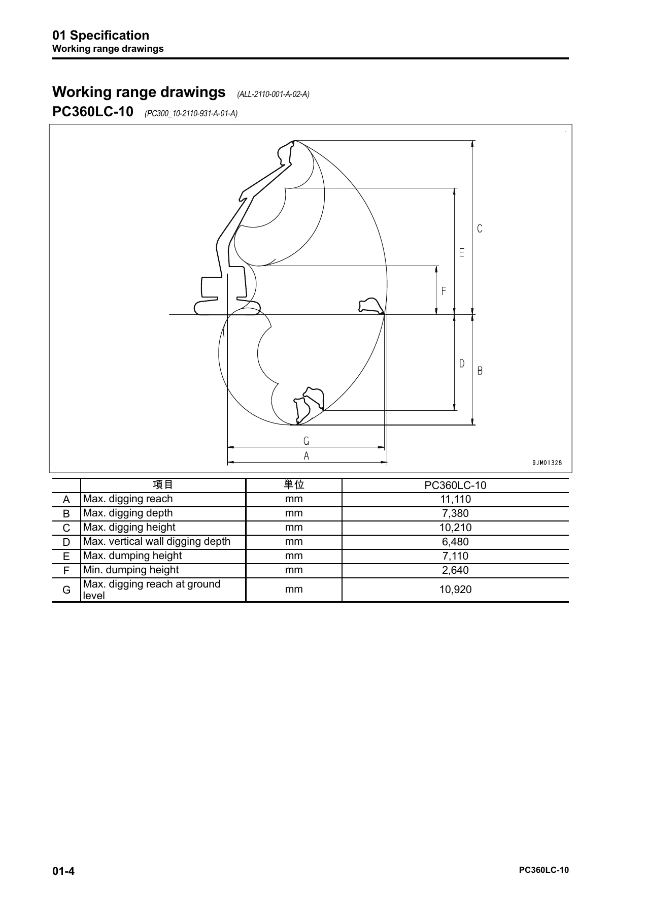
The specification chapter provides the full PC360LC-10 machine dimensions, working ranges, weight tables, bucket capacity, engine rated horsepower, swing speed, travel speeds and gradeability. A dedicated specification drawing shows the machine outline with dimension callouts for overall length, width, tail swing radius and track dimensions. The working range drawings detail maximum digging reach, maximum digging depth, maximum digging height, maximum vertical wall digging depth, maximum dumping height and minimum dumping height – all with the values Komatsu publishes for the PC360LC-10. The weight table breaks down every major component from the engine and main pump to the counterweight, boom, arm and bucket for safe lifting and transport planning.
Engine, Cooling and Aftertreatment
The structure and function chapter opens with the Komatsu SAA6D114E-5 engine, its related components and the cooling system. Full technical descriptions are provided for the Komatsu Variable Geometry Turbocharger (KVGT), the EGR system with piping diagrams and circuit diagrams, the EGR valve and EGR cooler, the Komatsu Closed Crankcase Ventilation (KCCV) system, and the Komatsu Diesel Particulate Filter (KDPF) including passive regeneration, automatic regeneration, manual stationary regeneration and the regeneration-for-service procedure. The cooling system, engine mounts and damper assembly are also covered with specifications and layout drawings. This section gives you the working principles behind the emission controls, not just the part locations.
Hydraulic and Powertrain Systems
The hydraulic system is documented in depth, starting with the CLSS (Closed-center Load Sensing System) and its pressure compensation, LS and PC control principles. The manual then covers the HPV140 + 140 main pump, including the PC valve, LS valve, LS-EPC valve, PC-EPC valve and servo piston operation. The control valve chapter details the 6-spool valve, service valve, merge-divider valve, boom drift prevention valve, arm quick return valve, travel junction valve, variable back pressure valve and main relief valves. Swing motor, travel motor, PPC valve, solenoid valve, attachment circuit selector valve, center swivel joint and accumulator are all covered with sectional views and operating principles. Powertrain sections describe the swing circle, swing machinery and final drive with reduction ratios and component layouts.
Electrical Control and Monitor Systems
The electrical control section covers the general system drawing, engine control function, engine and pump combined control function, pump and valve control function, one-touch power maximizing function, machine push-up function, auto-deceleration function, engine automatic warm-up function, overheat prevention function, turbocharger protection function, swing control function, travel control function, PPC lock function and the oil flow adjuster function for attachments. The machine monitor system chapter describes the display, alarm monitors, pilot monitors, switches, guidance icons and function switches, plus the operator mode and service mode functions. The KOMTRAX system, its terminal, antennas and input/output signals are documented. Detailed sensor descriptions cover the ambient pressure sensor, charge pressure and temperature sensor, coolant temperature sensor, Ne and Bkup speed sensors, common rail pressure sensor, exhaust manifold pressure sensor, EGR orifice temperature sensor, EGR valve lift sensor, KVGT speed and position sensors, mass air flow and temperature sensor, KDPF differential pressure and outlet pressure sensor, KDOC inlet and outlet temperature sensors, KDPF outlet temperature sensor, crankcase pressure sensor, engine oil level sensor, fuel level sensor, coolant level sensor, hydraulic oil temperature sensor, front and rear pump oil pressure sensors, PPC oil pressure sensors, air cleaner clogging sensor, pump swash plate sensors and water-in-fuel sensor.
Standard Values, Testing and Adjustment
The standard value tables provide the new-machine and repair-limit values for engine-related parts and the machine itself, including engine speed, boost pressure, exhaust gas color, valve clearance, compression pressure, blowby pressure, engine oil pressure, EGR valve and KVGT oil pressures, fuel pressure, fuel delivery/return/leakage values, swing and travel speeds, hydraulic drift, work equipment speed and time lag, oil leakage, pump swash plate sensor output, and main pump performance. The testing and adjusting chapter lists all required tools and sketches, then walks through engine speed testing, boost pressure testing, exhaust gas color testing, valve clearance adjustment, compression pressure testing, blowby pressure testing, engine oil pressure testing, EGR and KVGT oil pressure testing, fuel pressure testing, fuel discharge/return/leakage testing, air bleeding, fuel circuit leakage testing, cylinder cutout mode operation, no-injection cranking, fan and alternator belt replacement, swing circle bearing clearance testing, track tension adjustment, hydraulic circuit pressure release, work equipment/swing/travel circuit pressure testing, control circuit pressure testing, pump PC and LS control circuit pressure testing and adjustment, solenoid valve outlet pressure testing, PPC valve output pressure testing, PPC valve play adjustment, pump swash plate sensor testing, hydraulic drift isolation, oil leakage testing, hydraulic circuit air bleeding, cab tipping stopper check, mirror adjustment, rearview camera angle adjustment, engine controller voltage circuit handling, battery disconnect switch handling and diode testing.
Troubleshooting
The troubleshooting chapter is the largest in the manual, divided into failure-code-based troubleshooting, E-mode electrical system troubleshooting (E-1 through E-59), H-mode hydraulic and mechanical system troubleshooting (H-1 through H-36), and S-mode engine troubleshooting (S-1 through S-23). Failure codes covered include the full range of Komatsu engine and machine codes such as [879AKA], [989L00], [AA10NX], [AB00KE], [B@BAZG], [B@BCNS], [CA115] through [CA3741], plus the [D-series] and [DX-series] codes for the machine monitor, pump controller, KOMTRAX and electrical circuits. Each code entry shows the action level, failure name, details of failure, controller action, problem on machine, related information, cause, and step-by-step troubleshooting with measuring locations and criteria. The E-mode, H-mode and S-mode sections give you symptom-based diagnostics for everything from an engine that won’t crank to swing drift, travel deviation and unusual hydraulic noise.
Disassembly and Assembly
The disassembly and assembly chapter covers removal and installation of the supply pump assembly, injector assembly, cylinder head assembly, radiator, hydraulic oil cooler, aftercooler, engine and main pump assembly, engine front seal, engine rear seal, fuel tank, engine hood, KDPF assembly, KDPF disassembly, KCCV assembly, air cleaner, air conditioner compressor, and air conditioner condenser. Powertrain procedures cover the travel motor and final drive, final drive disassembly, swing motor and swing machinery, swing machinery disassembly, and swing circle. Undercarriage procedures cover track shoe separation and connection, sprocket, idler and idler cushion, idler disassembly, idler cushion disassembly, track roller, carrier roller, revolving frame, and counterweight. Hydraulic system procedures cover the center swivel joint, hydraulic tank, main pump, control valve, work equipment PPC valve and travel PPC valve. Work equipment procedures cover the bucket, arm, work equipment assembly and work equipment cylinder. Cab procedures cover the operator’s cab assembly, cab glass, front window assembly, floor frame assembly, air conditioner unit, operator’s seat, seat belt and front wiper. Electrical system procedures cover the engine controller, pump controller, machine monitor, pump swash plate sensor, mass air flow and temperature sensor, and KOMTRAX terminal.
Maintenance Standards
The maintenance standard chapter provides the judgment criteria, standard dimensions, tolerances, standard clearances, allowable clearances, standard interference, allowable interference, repair limits and allowable values for every major component. Sections cover the engine mount and cooling system, swing circle, swing machinery, final drive, sprocket, track frame and idler cushion, idler, track roller, carrier roller, track shoe, hydraulic tank, main pump, control valve, swing motor, travel motor, PPC valve (work equipment/swing and travel), solenoid valve, attachment circuit selector valve, center swivel joint, work equipment and work equipment cylinders. Spring free lengths, installed lengths and load values are also tabulated for the control valve, swing motor, travel motor, PPC valves and attachment circuit selector valve. These are the values you use to decide whether a component can be reused or must be replaced.
Air Conditioner Appendix
The appendix provides the complete air conditioner system reference, including refrigerant precautions, air conditioner components, the refrigeration cycle, air conditioner unit, dual pressure switch, air conditioner controller, compressor, condenser, receiver drier, sunlight sensor and outside air temperature sensor. Testing and troubleshooting procedures cover air leakage, self-diagnosis, electrical system abnormality record, vent mode changeover, FRESH/RECIRC air changeover, sunlight sensor testing, dual pressure switch testing and relay testing. Failure codes [879AKA] through [879GKX] and [DAZ9KQ]/[DAZQKR] are documented with full troubleshooting flowcharts, plus troubleshooting charts for the power supply system, compressor and refrigerant system, blower motor system, and FRESH/RECIRC air changeover. Gauge pressure troubleshooting, service tool connection, piping precautions and compressor oil handling are also included.
Diagrams and Drawings
The final chapter provides the complete hydraulic circuit diagram with symbols, the electrical circuit diagram with symbols, and the electrical circuit diagram for the air conditioner unit. These schematics are the same ones used by Komatsu service technicians and are indispensable for tracing circuits, locating components, and verifying connector and pin assignments during diagnostics or repair.
What This Komatsu PC360LC-10 Shop Manual Enables You to Do
Owning this Komatsu PC360LC-10 shop manual means you can perform the full range of service work on the machine without sending it to a dealer. Engine overhauls, injector replacement, supply pump service, cylinder head work and timing procedures are all covered with the torque sequences and tightening torques needed to reassemble correctly. The hydraulic section supports main pump removal and overhaul, control valve disassembly, PC valve and LS valve adjustment, swing motor and travel motor rebuilds, PPC valve servicing, and complete hydraulic circuit diagnosis using the supplied circuit diagram. The electrical section supports fault code diagnosis, controller replacement, sensor testing, machine monitor service mode entry, KOMTRAX terminal configuration, and full wiring harness troubleshooting with connector pinout references. Undercarriage and work equipment procedures support track tension adjustment, sprocket and idler replacement, track shoe separation, work equipment pin and bushing service, and cylinder resealing. Maintenance standards let you measure wear, verify clearances and decide whether a component is within reuse limits or must be replaced.
Who This PC360LC-10 Service Manual Is For
This manual is written for the professional heavy equipment technician, the independent repair shop, the fleet maintenance manager, and the owner-operator who services their own Komatsu PC360LC-10. It is also useful for technical trainers, apprentices learning the CLSS hydraulic system, and anyone preparing for Komatsu service certification. Because every procedure references the actual machine systems, the manual works equally well for scheduled maintenance, emergency repairs, component rebuilds, and diagnostic troubleshooting.
Why the Right PC360LC-10 Repair Manual Matters
The PC360LC-10 is a high-value hydraulic excavator with complex electronic and hydraulic systems. Using the wrong torque, clearance or adjustment can damage components, shorten service life or create safety hazards. This Komatsu PC360LC-10 shop manual gives you the correct procedures, the correct values and the correct sequence so that the machine goes back together right the first time. With 1,726 pages of detailed factory reference material, including technical drawings, sectional views and schematics, this is the most comprehensive single source for PC360LC-10 service information available as a downloadable PDF.
IMAGES PREVIEW
Instant PDF Delivery of the Komatsu PC360LC-10 Shop Manual SEN05619-03
This Komatsu PC360LC-10 shop manual is delivered as an instant PDF download. No shipping, no waiting, no physical media to lose. After purchase, the file is available immediately and can be viewed on any device – laptop, tablet or smartphone – and printed page by page for use in the workshop. The PDF format allows you to zoom into diagrams, jump between chapters and keep a permanent, portable copy of the manual on hand for every job. Whether you are in the shop, in the field or on the road, your PC360LC-10 service manual is always with you.
Reviews
There are no reviews yet.