
Komatsu PC360LC-10 PC390LC-10 Hydraulic Excavator Shop Manual 2010 – 2041 Pages PDF
Original price was: $42.95.$26.95Current price is: $26.95.
Complete 2041-page Komatsu shop manual for PC360LC-10 and PC390LC-10 hydraulic excavators with SAA6D114E-5 engine. Covers structure, function, testing, adjusting, troubleshooting, disassembly, assembly, maintenance standards, air conditioning and full diagrams.
Description
Komatsu PC360LC-10 & PC390LC-10 Shop Manual — Complete Workshop Reference
This is the full Komatsu shop manual for the PC360LC-10 and PC390LC-10 hydraulic excavators, powered by the SAA6D114E-5 engine. It is the same technical reference used by Komatsu service technicians for diagnosis, repair, adjustment and overhaul of these machines. The document runs 2,041 pages across nine major sections and covers serial numbers PC360LC-10 A32001 and up, PC360LC-10 K64001 and up, and PC390LC-10 A30001 and up.
File Details
- Manual type: Shop Manual (Workshop / Service Repair)
- Brand: Komatsu
- Models covered: PC360LC-10, PC390LC-10
- Engine: SAA6D114E-5 (6D114E-5)
- Serial numbers: PC360LC-10 A32001 and up; PC360LC-10 K64001 and up; PC390LC-10 A30001 and up
- Document number: CEBM025205
- Language: English
- Page count: 2,041 pages
- File format: PDF
Chapters Covered
- 01 GENERAL — Specification dimension drawings, working ranges, specifications (engine, undercarriage, hydraulic system), weight table, fuel/coolant/lubricant charts and lubrication chart
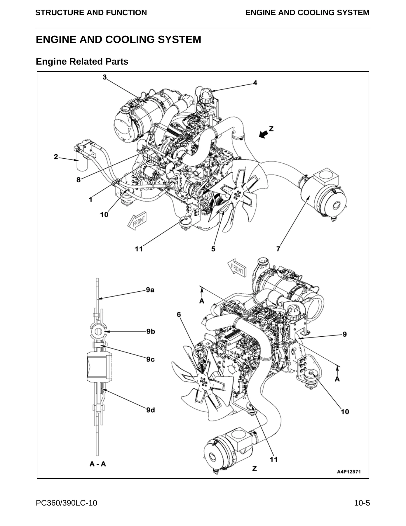
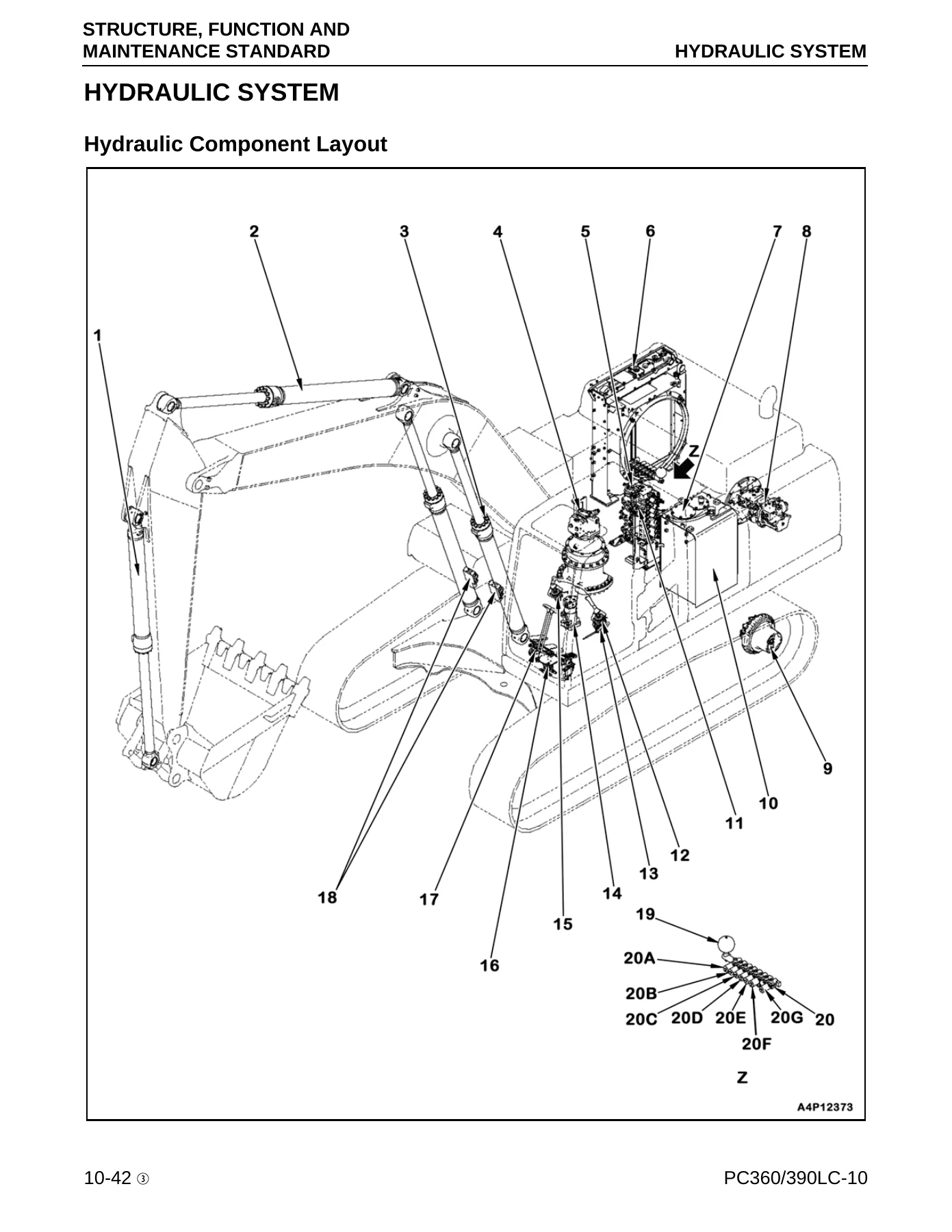
- 10 STRUCTURE AND FUNCTION — Engine and cooling system (KVGT, EGR, KCCV, KDPF, aftercooler), power train (swing circle, swing machinery, final drive), undercarriage and frame, hydraulic system (CLSS, main pump, LS valve, PC valve, EPC valve, control valve, travel motor, swing motor), work equipment, cab and attachments, electrical control system, machine monitor system, KOMTRAX and all sensors
- 20 STANDARD VALUE TABLES — Engine standard values, chassis standard values, engine speed, control valve spool travel, control lever travel, operating effort, hydraulic pressure, swing, travel, work equipment and combined-operation performance limits
- 30 TESTING AND ADJUSTING — Tools, engine speed checks, boost pressure, exhaust gas color, valve clearance, compression pressure, blow-by, engine oil pressure, EGR and KVGT pressure, fuel pressure, fuel delivery/return/leakage, air bleeding, swing circle clearance, track tension, hydraulic relief pressures, LS differential pressure, PC-EPC and LS-EPC output pressures, PPC output pressure, pump swash plate sensor testing, oil leakage measurement, air bleeding from hydraulic circuit, cab and electrical checks, PM Clinic service sheets
- 40 TROUBLESHOOTING — General troubleshooting procedure, checks before troubleshooting, E-mode (electrical), H-mode (hydraulic/mechanical), S-mode (engine), failure code table with full diagnostic procedures and circuit diagrams
- 50 DISASSEMBLY AND ASSEMBLY — How to read the section, coating materials list, special tools, connector repair, supply pump, injector, cylinder head, radiator, hydraulic oil cooler, aftercooler, engine and main pump, engine front/rear oil seals, fuel tank, engine hood, KDPF, KCCV, air cleaner, A/C compressor and condenser, travel motor and final drive, swing motor and swing machinery, swing circle, track shoe, sprocket, idler and idler cushion, track roller, carrier roller, revolving frame, counterweight, center swivel joint, hydraulic tank, main pump, control valve, PPC valves, bucket, arm, work equipment assembly, cylinders, operator’s cab, cab glass, front window, floor frame, A/C unit, operator’s seat, seat belt, wiper, engine controller, pump controller, machine monitor, pump swash plate sensor, mass air flow sensor and KOMTRAX terminal
- 60 MAINTENANCE STANDARD — Engine mounts, cooling system, power train (swing machinery, final drive), undercarriage (idler, idler cushion, track roller, carrier roller, track shoe, triple grouser shoe), hydraulic system (hydraulic tank, main pump, control valve, PPC valve, EPC valve, solenoid valve, attachment circuit selector, center swivel joint), work equipment dimensions, boom/arm/bucket cylinders
- 80 AIR CONDITIONING — Refrigerant precautions, component layout, refrigeration cycle, air conditioner unit, dual pressure switch, controller, compressor, condenser, receiver drier, sensors, testing and troubleshooting (self-diagnosis, vent changeover, FRESH/RECIRC, sunlight sensor, pressure switch, relay), gauge pressure diagnostics, refrigerant piping and compressor oil handling
- 90 DIAGRAMS AND DRAWINGS — Hydraulic circuit symbols and diagram, electrical circuit symbols, electrical circuit diagrams (1/6 to 6/6) and air conditioner electrical circuit
Every chapter is written as a working reference, not a summary. The structure and function section explains how each hydraulic and electrical system actually operates on these specific machines, including the CLSS closed-centre load-sensing system, the LS and PC valve behaviour, the EPC valve operation, and the KDPF regeneration strategy. The testing and adjusting section gives the exact tools, measuring conditions and target values required before a repair can be judged correct. The troubleshooting section pairs failure codes with a numbered diagnostic sequence so a technician can move from symptom to root cause without guesswork. The disassembly and assembly section provides step-by-step removal, installation, disassembly and assembly procedures with tightening torques, coating materials and special tool references throughout.
What This Manual Enables You To Do
This shop manual supports the complete range of professional work on the PC360LC-10 and PC390LC-10: engine and cooling system service including KVGT, EGR, KCCV and KDPF components; hydraulic pump, control valve, LS/PC/EPC valve diagnosis and adjustment; swing and travel motor overhaul; final drive and swing machinery disassembly and assembly; undercarriage inspection and component replacement; work equipment cylinder repair; electrical troubleshooting with full circuit diagrams; machine monitor and controller diagnostics; and air conditioning system testing, repair and refrigerant handling.
The value here is having the correct procedure and the correct specification at the same time. A hydraulic relief pressure adjustment, a pump swash plate sensor calibration, a valve clearance setting, a final drive preload or a wiring harness diagnosis all depend on values and sequences that are only meaningful when they come from the manufacturer’s own reference. This manual provides those values and sequences in one place, organised by system and by symptom, so the diagnosis can be confirmed before any parts are ordered or any assembly is closed up.
IMAGES PREVIEW
Delivered as an instant PDF download. No shipping, no waiting. The file can be opened on any device, searched and printed as needed, so it can sit on a workshop laptop or be printed as a bench copy for the section currently being worked on.

Reviews
There are no reviews yet.