
Komatsu PC360LC-11 & PC390LC-11 Hydraulic Excavator Shop Manual – Complete PDF Service & Repair Guide
Original price was: $79.95.$49.95Current price is: $49.95.
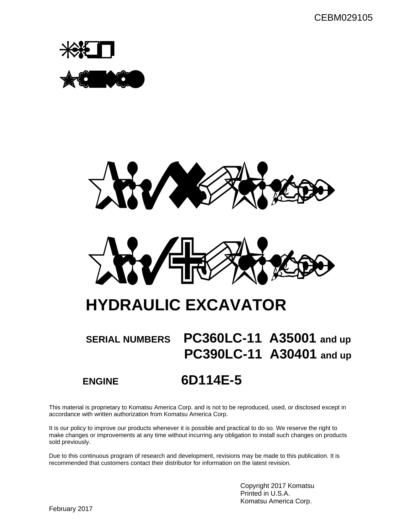
The complete Komatsu Shop Manual for PC360LC-11 and PC390LC-11 hydraulic excavators. Over 2,250 pages covering engine, hydraulics, electrical, troubleshooting, disassembly & assembly. Publication CEBM029105. Instant PDF download.
Description
Komatsu PC360LC-11 & PC390LC-11 Shop Manual – The Complete Two-Volume Workshop Reference
This is the full Komatsu Shop Manual for the PC360LC-11 and PC390LC-11 hydraulic excavators, issued under publication number CEBM029105. It covers machines from serial PC360LC-11 A35001 and up and PC390LC-11 A30401 and up, with the 6D114E-5 engine (specification tables list the SAA6D114E-6). The manual is split across two volumes and runs to more than 2,250 pages of procedures, specifications, diagrams, and repair data. Every chapter from specifications through disassembly, maintenance standards, and circuit diagrams is present — nothing excerpted, nothing summarised.
File Details
- Manual type: Shop Manual (Service & Repair)
- Brand: Komatsu
- Models covered: PC360LC-11, PC390LC-11
- Serial numbers: PC360LC-11 A35001 and up; PC390LC-11 A30401 and up
- Engine: 6D114E-5 (spec tables: SAA6D114E-6)
- Publication number: CEBM029105
- Language: English
- File format: PDF
- Page count: 2253+ (two volumes)
Chapters Covered
- 00 Index and Foreword
- 01 Specifications
- 10 Structure and Function
- 20 Standard Value Table
- 30 Testing and Adjusting
- 40 Troubleshooting
- 50 Disassembly and Assembly
- 60 Maintenance Standard
- 80 Appendix
- 90 Circuit Diagrams
00 – Index and Foreword
Abbreviation lists for the entire manual and circuit diagrams, safety notices covering operation, fire prevention and fire response, waste disposal, exhaust gas regulations, and detailed precautions for DEF handling and storage. Also includes disconnection and connection procedures for push-pull couplers, Deutsch connectors, slide-lock connectors, and lock-to-pull/push connectors, plus how to read electrical wire codes, maintenance standard terminology, the standard tightening torque tables, and the full conversion table.
01 – Specifications
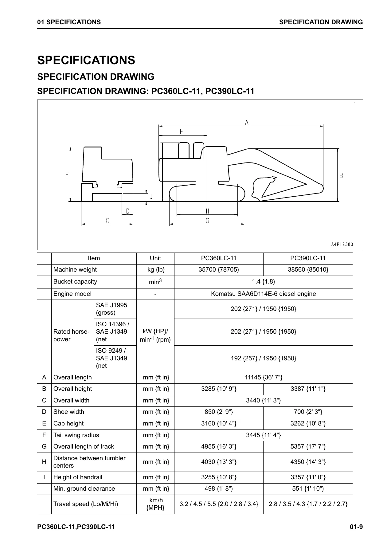
Full specification drawings and working range drawings for both models. Includes bucket capacity, machine weight, rated horsepower (gross and net), overall dimensions, track dimensions, travel speeds, swing speed, gradeability, ground pressure, engine data (bore × stroke, displacement, compression ratio, fuel consumption), hydraulic pump and motor details, cylinder bore/rod/stroke dimensions, and the complete weight table for every major assembly. The fuel, coolant, and lubricants table rounds out the chapter.
10 – Structure and Function
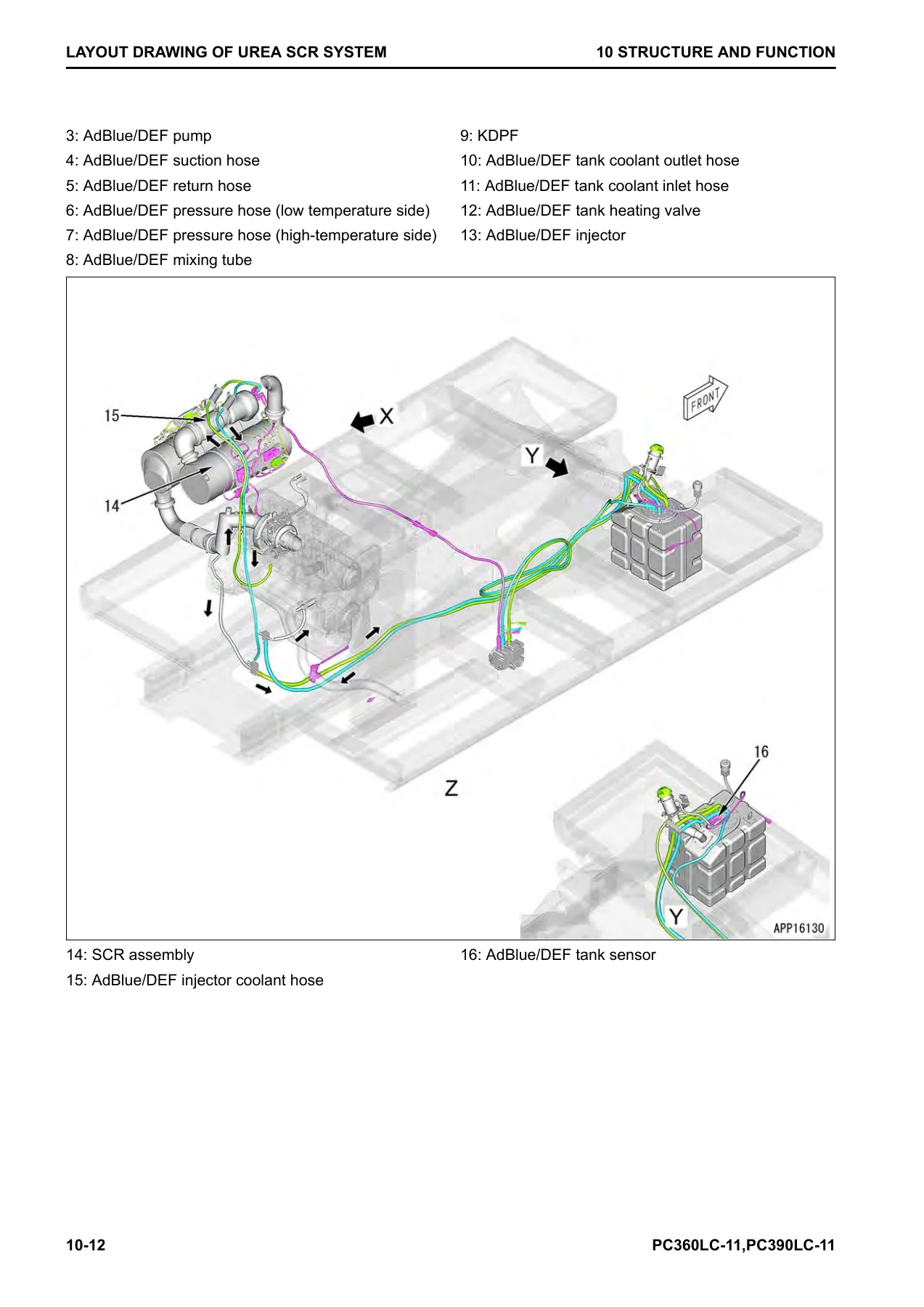
System-by-system explanation of how the machine works. Covers the Urea SCR system (layout, diagram, function, component parts, inducement strategy for North America and European Union, temporary restoration, and abnormality recurrence strategy), the boot-up system and system operating lamp, engine control system (auto-deceleration, automatic warm-up, overheat prevention, automatic idle stop), cooling system, control system (machine monitor, KOMTRAX), hydraulic system (CLSS, engine and pump combined control, pump and valve control, LS valve, PC valve, pressure compensation, LS bypass, LS select), work equipment system (valve control, PPC levers, one-touch power maximizing, machine push-up, PPC lock), swing system, travel system, undercarriage, work equipment, cab and attachments, and the component parts of each system.
20 – Standard Value Table
The reference chapter for every measured value. Engine standard values (speed at high idle and low idle, boost pressure, exhaust gas colour, valve clearance, compression pressure, blowby pressure, fuel pressure, supply pump discharge, return rates, engine oil pressure, EGR and VGT oil pressure, air conditioner belt tension) and machine standard values (engine speed at relief and auto-deceleration, control valve spool stroke, lever travel and play, operating effort, work equipment/swing/travel oil pressures, PC and LS valve output pressures, EPC valve pressures, solenoid valve outlet pressures, PPC valve output pressures, swing overrun and drift, travel speed and deviation, hydraulic drift, work equipment speed, operation time lag, oil leakage, pump performance, pump swash plate sensor voltage). Electrical standard value table with controller power supply voltages, sensor resistances and output voltages, solenoid resistances, and pressure sensor voltages.
30 – Testing and Adjusting
Every test and adjustment procedure a technician needs, with the required tools listed. Engine and cooling: engine speed, boost pressure, exhaust gas colour, valve clearance, compression pressure, blowby pressure, engine oil pressure, EGR and VGT oil pressure, fuel pressure, fuel discharge and return and leakage, bleeding air from the fuel system, fuel circuit leakage, cylinder cut-out mode operation, no-injection cranking, air conditioner compressor belt tension, ash in soot accumulation correction, and SCR-related functions (AdBlue/DEF pump raised pressure, injection amount, line heater relays, pump heater relay, tank heater valve, denitration efficiency). Power train: swing circle bearing clearance. Undercarriage: track tension. Hydraulic system: releasing remaining pressure, testing and adjusting oil pressure in work equipment/swing/travel circuits, control circuit oil pressure, pump PC and LS control circuits, solenoid valve outlet pressure, PPC valve output pressure, work equipment and swing PPC valve play, pump swash plate sensor, parts causing hydraulic drift, oil leakage, and bleeding air from the hydraulic circuit. Cab and electrical: cab tipping stopper, mirror adjustment, machine monitor set and operate, KOMTRAX start-up, rearview camera angle, engine controller voltage circuit, battery disconnect switch, and diode testing.
40 – Troubleshooting
The largest chapter. Begins with general troubleshooting points, specific points for the Urea SCR system (engine controller shutdown, loaded diagnostics, clearing failure codes, how to identify the failure code to be repaired, troubleshooting flow, and the list of failure codes related to Inducement), sequence of events, checks before troubleshooting, inspection procedure, and testing procedure. Then the failure codes table and troubleshooting by failure code, covering hundreds of codes from [879AKA] through [DFB4L8]. E-mode electrical troubleshooting covers everything from engine does not start and preheating faults through monitor, gauge, sensor, switch, horn, wiper, washer, and attachment circuit issues. H-mode hydraulic and mechanical troubleshooting covers all work equipment, swing and travel faults, boom/arm/bucket speed and power, hydraulic drift, combined operation, travel, steering, and swing. S-mode engine troubleshooting covers engine does not crank, no exhaust gas, misfiring, poor startability, rough running, lack of power, KDPF clogging, oil consumption, contamination, fuel consumption, coolant and oil mixing, oil pressure drop, overheating, unusual noise, vibration, air bleeding, active regeneration frequency and duration, white smoke, AdBlue/DEF consumption, unusual smell, and foreign materials in AdBlue/DEF.
50 – Disassembly and Assembly
Step-by-step removal, installation, disassembly, and assembly procedures with special tools, tightening torques, coating materials, and weights. Engine and cooling: supply pump, injector, cylinder head, EGR valve and cooler, starter, alternator belt, radiator, hydraulic oil cooler, aftercooler, engine and main pump, front and rear oil seals, engine hood, fuel tank, AdBlue/DEF tank, tank sensor flange, tank sensor, tank strainer, KDPF, SCR, KDPF and SCR bracket, KCCV, AdBlue/DEF mixing tube, AdBlue/DEF injector, AdBlue/DEF pump, AdBlue/DEF hose, air cleaner, and air conditioner compressor and condenser. Power train: travel motor and final drive, final drive disassembly/assembly, swing motor and swing machinery, swing machinery disassembly/assembly, swing circle. Undercarriage and frame: track assembly separation and connection, sprocket, idler and idler cushion, idler disassembly/assembly, idler cushion disassembly/assembly, track roller, carrier roller, revolving frame, counterweight. Hydraulic system: center swivel joint, hydraulic tank, main pump, control valve, work equipment PPC valve, travel PPC valve. Work equipment: bucket, arm, work equipment assembly, anti-drop valve for boom and arm, work equipment cylinder. Cab: operator cab, cab glass, front window, floor frame, air conditioner unit, operator seat, seat belt, front wiper. Electrical: engine controller, pump controller, machine monitor, pump swash plate sensor, mass air flow and temperature sensor, KCCV crankcase pressure sensor, SCR temperature sensor, rearview camera, KOMTRAX terminal.
60 – Maintenance Standard
Maintenance standard values for every major component: engine mount, cooling system, swing circle, swing machinery, final drive, sprocket and sprocket tooth profile, track frame and idler cushion, idler, track roller, carrier roller, track shoe, triple shoe, hydraulic tank, main pump, swing motor, travel motor, control valve, anti-drop valve for boom and arm, work equipment and swing PPC valve, travel PPC valve, 1st-line attachment PPC valve, 2nd-line attachment PPC valve, solenoid valve, attachment circuit selector valve, center swivel joint, and work equipment linkage, boom cylinder, arm cylinder, and bucket cylinder.
80 – Appendix
The air conditioner system chapter. Covers refrigerant precautions, air conditioner components and specifications, refrigeration cycle configuration and function, component parts of the air conditioner unit, air conditioner controller, compressor, condenser, receiver drier, sensors, testing and troubleshooting procedures including air leakage, self-diagnosis, vent mode changeover, fresh/recirc changeover, sunlight sensor, dual pressure switch, relays, and the air conditioner troubleshooting charts with failure codes from [879AKA] through [879GKX]. Also covers gauge pressure troubleshooting, service tool connection, and precautions for disconnecting and connecting air conditioner piping.
90 – Circuit Diagrams
Hydraulic circuit diagram with symbols, and electrical circuit diagrams split across eight pages, with the symbols used in the electrical circuit diagrams. These are the full system schematics for tracing and diagnosing hydraulic and electrical faults.
Who This Shop Manual Is For
This is the same class of documentation used in Komatsu service workshops. It suits independent heavy equipment mechanics, fleet maintenance departments, excavator owners who do their own repair work, and anyone studying the PC360LC-11 or PC390LC-11 platform in depth. The combination of structure and function, testing and adjusting, troubleshooting, disassembly and assembly, and maintenance standard in one document means you are not jumping between separate publications to complete a job.
IMAGES PREVIEW
Everything You Need for Diagnosis, Repair, and Rebuild — Instant PDF Download
Whether you are chasing an electrical fault on the machine monitor, setting up the hydraulic system after a pump repair, pulling the cylinder head, resealing a final drive, or working through a SCR inducement code, the relevant procedure, specification, torque value, and diagnostic flow are in this manual. The structure and function chapter tells you how the system is meant to behave; the standard value table tells you what good looks like; the testing and adjusting chapter shows you how to measure and correct it; the troubleshooting chapter walks you through the fault; and the disassembly and assembly chapter covers the physical repair with tooling, torques, and coating materials.
Having the correct procedures and specifications matters on a machine of this size. An incorrect torque, a missed seal, a misdiagnosed sensor, or a hydraulic adjustment made by feel rather than by the book can turn a straightforward repair into a repeat failure. This manual removes the guesswork.
Delivered as an instant PDF download — no shipping, no waiting. Read it on a laptop, tablet, or phone in the workshop, or print the pages you need for the job. The file is yours to keep and reference for the life of the machine.
Reviews
There are no reviews yet.