★ TRUSTED BY 321,897+ PROFESSIONALS WORLDWIDE
🏢
Trusted Business
Verified & Licensed
🛡️
Virus Free Files
100% Safe Downloads
🔒
Secure Payment
SSL Protected
Instant Delivery
Available Immediately
Sale!

Komatsu PC490LC-10 Hydraulic Excavator Shop Manual SEN05622-01 April 2011 – Complete Workshop Repair & Service Guide

Original price was: $39.95.Current price is: $24.95.

Complete Komatsu PC490LC-10 Hydraulic Excavator Shop Manual SEN05622-01 (April 2011). Approximately 1,600 pages covering engine, hydraulics, electrical, troubleshooting, disassembly, maintenance standards, air conditioning and circuit diagrams for machines from serial 80001 up.

Instant PDF Download
Available immediately
💾
Save to Your Device
Download & keep forever
🛡️
Antivirus Scanned
100% virus-free
🌍
Trusted Worldwide
175,000+ customers

Description

Komatsu PC490LC-10 Hydraulic Excavator Shop Manual SEN05622-01

This is the complete Komatsu PC490LC-10 Hydraulic Excavator Shop Manual, document number SEN05622-01, dated April 2011, covering machines from serial number 80001 and up. At approximately 1,600 pages, this is the full workshop service and repair guide for the PC490LC-10, covering the SAA6D125E-6 diesel engine, hydraulic systems, electrical control systems, undercarriage, work equipment, operator cab, and air conditioning. It is written for technicians who need factory-level procedures, exact specifications, and systematic troubleshooting guidance for every major assembly on the machine.

File Details

  • Manual type: Shop Manual (Service Repair Workshop Manual)
  • Brand: Komatsu
  • Model: PC490LC-10 Hydraulic Excavator
  • Engine: Komatsu SAA6D125E-6 diesel engine
  • Serial number range: 80001 and up
  • Document number: SEN05622-01
  • Date: April 2011
  • Language: English
  • Page count: Approximately 1,600 pages
  • File format: PDF

Chapters Covered

The manual is organised into ten top-level sections that together cover the entire machine:

  • 00 – Index and Foreword: Safety notices, general precautions, how to read the manual, maintenance standard terminology, handling of fuel/intake/hydraulic/electrical equipment, push-pull coupler procedures, electric wire code, tightening torque tables, abbreviations, conversion tables.
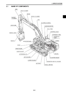
  • 01 – Specification: Machine specifications, specification drawings, working range drawings, weight table, fuel/coolant/lubricants table.
  • 10 – Structure and Function: Engine and cooling system, cooling fan pump and motor, power train, swing circle, swing machinery, final drive, undercarriage and frame, hydraulic component layout, CLSS, main pump, control valve, swing motor, travel motor, PPC valve, solenoid valve, attachment circuit selector valve, center swivel joint, accumulator, work equipment, cab and attachments, electrical control system, machine monitor system, KOMTRAX, sensors.
  • 20 – Standard Value Table: Standard service values for engine and machine, including judgment criteria for testing and troubleshooting.
  • 30 – Testing and Adjusting: Engine speed, boost pressure, exhaust gas temperature and colour, valve clearance, compression pressure, blowby pressure, engine oil pressure, EGR and KVGT oil pressure, fuel pressure and leakage, air bleeding, cylinder cutout mode, no-injection cranking, belt tension, fuel doser cleaning, injector/controller compensation values, swing circle bearing clearance, track shoe tension, hydraulic pressure measurement and adjustment across work equipment, swing, travel, control, PC and LS circuits, solenoid and PPC output pressures, pump swash plate sensor, fan pump circuit, oil leakage, air bleeding, cab tipping stopper, mirror adjustment, camera angle, battery disconnect switch, diodes, Pm clinic check sheets.
  • 40 – Troubleshooting: General troubleshooting procedure, checks before troubleshooting, classification, symptom index, connector layout, failure codes table, troubleshooting by failure code (air conditioner sensors, engine controller lock, KDPF requests, air cleaner clogging, charge voltage, engine oil pressure/level, coolant overheat/level, hydraulic oil overheat, engine speed sensors, charge air pressure/temperature, throttle sensor, coolant temperature, sensor supplies, ambient pressure, engine overspeed, injector circuits, rail pressure, battery voltage, EGR, KVGT, mass air flow, DPF/KDOC temperatures and pressures, doser valves, CAN communication, monitor errors, pump controller errors, fan speed, travel and swing solenoids, PPC sensors, wiper, and more).
  • 50 – Disassembly and Assembly: Removal, installation, disassembly and assembly of supply pump, injectors, cylinder head, radiator, hydraulic oil cooler, aftercooler, cooling fan and motor, engine and main pump, engine front and rear seals, engine hood, KDPF, KCCV, air cleaner, travel motor and final drive, swing motor and machinery, swing circle, track shoe, sprocket, idler, idler cushion, track roller, carrier roller, revolving frame, counterweight, center swivel joint, hydraulic tank, main pump, control valve, work equipment PPC valve, travel PPC valve, work equipment, work equipment cylinder, operator cab, cab glass, front window, floor frame, air conditioner unit, operator seat, seat belt, front wiper, air conditioner compressor, condenser, engine controller, pump controller, machine monitor, pump swash plate sensor, mass air flow sensor, KOMTRAX terminal.
  • 60 – Maintenance Standard: Maintenance standards for engine mount, cooling system, cooling fan pump and motor, swing circle, swing machinery, final drive, sprocket, track frame and idler cushion, idler, track roller, carrier roller, track shoe, main pump, control valve, swing motor, travel motor, PPC valve, solenoid valve, attachment circuit selector valve, center swivel joint, work equipment, work equipment cylinders.
  • 80 – Appendix (Air Conditioner): Refrigerant precautions, air conditioner components, refrigeration cycle, air conditioner unit, dual pressure switch, controller, compressor, condenser, receiver drier, sunlight sensor, outside air temperature sensor, testing and troubleshooting, circuit diagrams, connector layout, self-diagnosis, vent and FRESH/RECIRC testing, gauge pressure troubleshooting, service tool connection, piping precautions, compressor oil handling.
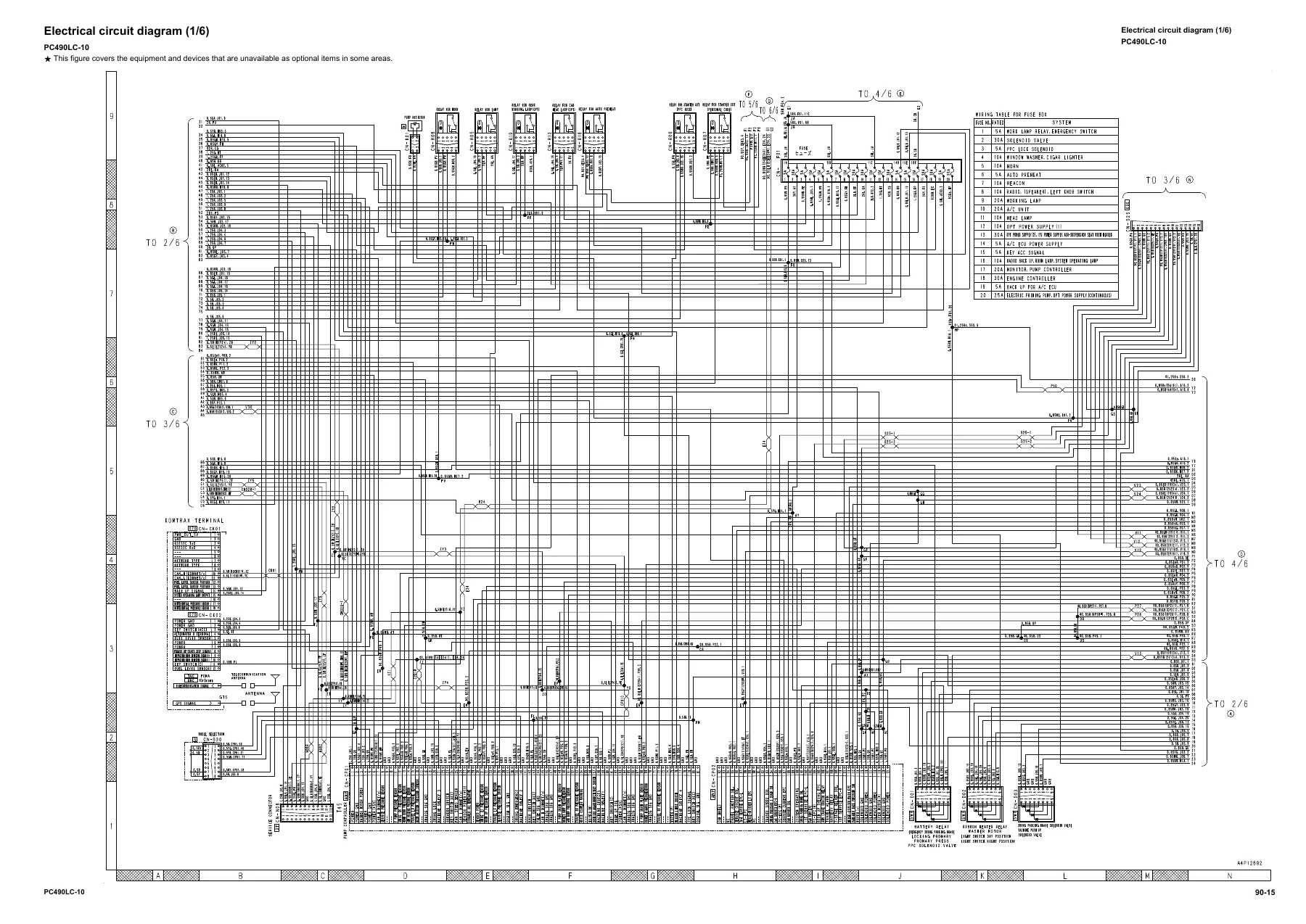
  • 90 – Diagrams and Drawings: Hydraulic circuit diagram with symbols, electrical circuit diagram with symbols, air conditioner unit electrical circuit diagram.

Complete PDF Bookmark Tree

Complete Bookmarks

The complete bookmarks in the “Komatsu PC490LC-10 Hydraulic Excavator Shop Manual SEN05622-01 April 2011 – Complete Workshop Repair & Service Guide” are as follows:

01 Specificationp. 60
Specificationsp. 61
Specification drawingp. 61
Working range drawingp. 62
Specificationp. 63
Table of weightp. 66
Table of fuel, coolant and lubricantsp. 67
10 Structure and function
Engine and cooling systemp. 71
Engine-related partsp. 71
Cooling systemp. 73
Cooling fan pumpp. 76
Cooling fan motorp. 86
Power train systemp. 94
Power trainp. 94
Swing circlep. 96
Swing machineryp. 97
Final drivep. 99
Undercarriage and framep. 101
Track frame and idler cushionp. 101
Hydraulic systemp. 103
Hydraulic component layoutp. 103
Valve controlp. 105
Hydraulic tankp. 107
CLSSp. 110
Main pumpp. 115
Control valvep. 138
Swing motorp. 192
Travel motorp. 203
PPC valvep. 218
Solenoid valvep. 237
Attachment circuit selector valvep. 240
Center swivel jointp. 243
Accumulatorp. 245
Work equipmentp. 246
Work equipment shimsp. 247
Bucket play adjustment shimp. 248
Cab and its attachmentsp. 249
Cab mount and cab tipping stopperp. 249
ROPS cabp. 250
Electrical systemp. 251
Electrical control systemp. 251
Machine monitor systemp. 300
KOMTRAX systemp. 318
Sensorsp. 320
30 Testing and Adjusting
General information on testing and adjusting
Tools for testing and adjusting
Sketch of tools for testing and adjusting
Engine and cooling system
Checking engine speed
Measuring boost pressure
Measuring exhaust gas temperature
Measuring exhaust gas color
Measuring and adjusting valve clearancep. 372
Measuring compression pressurep. 375
Measuring blowby pressurep. 377
Measuring engine oil pressurep. 378
Measuring EGR valve and KVGT oil pressurep. 380
Measuring fuel pressurep. 381
Measuring fuel leakage and returnp. 383
Bleeding air from fuel systemp. 386
Checking fuel circuit for leakagep. 388
Handling cylinder cutout mode operationp. 389
Handling no injection cranking operationp. 390
Checking and adjusting air conditioner compressor belt tensionp. 391
Replacing alternator beltp. 392
Fuel doser cleaning procedurep. 393
Writing compensation values at replacement of injector and engine controllerp. 396
Power train
Testing swing circle bearing clearance
Undercarriage and frame
Testing and adjusting track shoe tensionp. 401
Hydraulic system
Releasing remaining pressure from hydraulic circuit
Measuring and adjusting oil pressure in work equipment, swing and travel circuits
Measuring oil pressure in control circuit
Measuring and adjusting oil pressure in pump PC control circuitp. 409
Measuring and adjusting oil pressure in pump LS control circuitp. 412
Measuring solenoid valve output pressurep. 417
Measuring PPC valve output pressurep. 420
Adjusting play of work equipment and swing PPC valvesp. 422
Testing pump swash plate sensorp. 423
Measuring fan pump circuit oil pressurep. 424
Checking fan pump EPC currentp. 425
Measuring fan pump EPC solenoid valve output pressurep. 426
Isolating the parts causing hydraulic drift in work equipmentp. 427
Measuring oil leakagep. 428
Bleeding air from hydraulic circuitp. 431
Cab and its attachments
Checking cab tipping stopper
Adjusting mirrors
Electrical system
Special functions of machine monitor
Angle adjustment of rear view camera
Handling voltage circuit of engine controller
Handling battery disconnect switch
Testing diodesp. 510
Pm clinicp. 511
Check sheetp. 514
20 Standard value table
Standard service value table
Standard value table for engine
Standard value table for machine
40 Troubleshooting
General information on troubleshooting
Instruction on troubleshooting
Sequence of events in troubleshooting
Checks before troubleshooting
Testing procedure before troubleshooting
Classification and procedure for troubleshootingp. 541
Symptom and troubleshooting numbersp. 544
Information mentioned in troubleshooting tablep. 547
Connector list and layoutp. 550
Connector contact identificationp. 561
T-branch box and T-branch adapter tablep. 598
Connection table of fuse boxp. 604
Precautions for cleaning and replacing KDPF (KCSF, KDOC)p. 606
Failure codes tablep. 608
Troubleshooting by failure code (Display of code)
Failure code [879AKA] Air Conditioner Inner Sensor Disconnection
Failure code [879AKB] Air Conditioner Inner Sensor Disconnection
Failure code [879BKA] Air Conditioner Outside Air Sensor Disconnection
Failure code [879BKB] Air Conditioner Outside Air Sensor Disconnection
Failure code [879CKA] Ventilating Sensor Disconnection
Failure code [879CKB] Ventilating Sensor Short Circuit
Failure code [879DKZ] Sunlight Sensor Open Or Short Circuit
Failure code [879EMC] Ventilation Abnormal
Failure code [879FMC] A/M Damper Abnormal
Failure code [879GKX] Refrigerant Abnormality
Failure code [989L00] Engine Controller Lock Caution 1
Failure code [989M00] Engine Controller Lock Caution 2
Failure code [989N00] Engine Controller Lock Caution 3
Failure code [A1U0N3]: KDPF Dry Request (HC Release)
Failure code [A1U0N4] KDPF Dry Request (HC Release)
Failure code [AA10NX] Air Cleaner Clogging
Failure code [AB00KE] Charge Voltage Low
Failure code [B@BAZG] Eng Oil Press Low
Failure code [B@BAZK] Eng Oil Level Low
Failure code [B@BCNS] Eng Water Overheatp. 640
Failure code [B@BCZK] Eng Water Level Lowp. 641
Failure code [B@HANS] Hyd Oil Overheatp. 643
Failure code [CA115] Eng Ne and Bkup Speed Sens Errorp. 644
Failure code [CA122] Chg Air Press Sensor High Errorp. 645
Failure code [CA123] Chg Air Press Sensor Low Errorp. 647
Failure code [CA131] Throttle Sensor High Errorp. 649
Failure code [CA132] Throttle Sensor Low Errorp. 651
Failure code [CA135] Eng Oil Press Sensor High Errorp. 653
Failure code [CA141] Eng Oil Press Sensor Low Errorp. 655
Failure code [CA144] Coolant Temp Sens High Errorp. 657
Failure code [CA145] Coolant Temp Sens Low Errorp. 659
Failure code [CA153] Chg Air Temp Sensor High Errorp. 661
Failure code [CA154] Chg Air Temp Sensor Low Errorp. 663
Failure code [CA187] Sens Supply 2 Volt Low Errorp. 665
Failure code [CA221] Ambient Press Sens High Errorp. 667
Failure code [CA222] Ambient Press Sens Low Errorp. 669
Failure code [CA227] Sens Supply 2 Volt High Errorp. 671
Failure code [CA234] Eng Overspeedp. 672
Failure code [CA238] Ne Speed Sens Supply Volt Errorp. 673
Failure code [CA239] Ne Speed Sens Supply Volt High Errorp. 674
Failure code [CA271] IMV/PCV1 Short Errorp. 675
Failure code [CA272] IMV/PCV1 Open Errorp. 676
Failure code [CA273] PCV2 Short Errorp. 677
Failure code [CA274] PCV2 Open Errorp. 678
Failure code [CA322] Inj #1(L#1) Open/Short Errorp. 679
Failure code [CA323] Inj #5 (L#5) Open/Short Errorp. 681
Failure code [CA324] Inj #3(L#3) Open/Short Errorp. 683
Failure code [CA325] Inj #6 (L#6) Open/Short Errorp. 685
Failure code [CA331] Inj #2(L#2) Open/Short Errorp. 687
Failure code [CA332] Inj #4 (L#4) Open/Short Errorp. 689
Failure code [CA343] ECM Critical Internal Failurep. 691
Failure code [CA351] Injectors Drive Circuit Errorp. 692
Failure code [CA352] Sens Supply 1 Volt Low Errorp. 693
Failure code [CA356] Mass Air Flow Sensor High Errorp. 695
Failure code [CA357] Mass Air Flow Sensor Low Errorp. 697
Failure code [CA386] Sens Supply 1 Volt High Errorp. 699
Failure code [CA441] Battery Voltage Low Errorp. 700
Failure code [CA442] Battery Voltage High Errorp. 702
Failure code [CA449] Rail Press Very High Errorp. 703
Failure code [CA451] Rail Press Sensor High Errorp. 704
Failure code [CA452] Rail Press Sensor Low Errorp. 706
Failure code [CA515] Common Rail Pressure Sensor Power Supply Low Errorp. 708
Failure code [CA516] Common Rail Pressure Sensor Power Supply High Errorp. 710
Failure code [CA553] Rail Press High Errorp. 712
Failure code [CA555] Crankcase Press High Error 1p. 713
Failure code [CA556] Crankcase Pressure High Error 2p. 714
Failure code [CA559] Supply Pump Press Low Error 1p. 715
Failure code [CA595] Turbocharger Speed High Error 2p. 719
Failure code [CA687] Turbocharger Speed Low Errorp. 720
Failure code [CA689] Eng Ne Speed Sensor Errorp. 722
Failure code [CA691] Intake Temperature Sensor High Errorp. 724
Failure code [CA692] Intake Temperature Sensor Low Errorp. 726
Failure code [CA697] ECM Internal Temp Sensor High Errorp. 728
Failure code [CA698] ECM Internal Temp Sensor Low Errorp. 729
Failure code [CA731] Eng Bkup Speed Sens Phase Errorp. 730
Failure code [CA778] Eng Bkup Speed Sensor Errorp. 731
Failure code [CA1117] Engine Controller Partial Data Lost Errorp. 733
Failure code [CA1664] KDOC Malfunctionp. 734
Failure code [CA1691] Regeneration Ineffectivep. 736
Failure code [CA1695] Sens supply 5 volt high errorp. 739
Failure code [CA1696] Sens supply 5 volt low errorp. 740
Failure code [CA1843] Crankcase Pressure Sensor High Errorp. 742
Failure code [CA1844] Crankcase Press Sensor Low Errorp. 744
Failure code [CA1879] KDPF Delta Pressure Sensor High Errorp. 746
Failure code [CA1881] KDPF Delta Pressure Sensor Low Errorp. 748
Failure code [CA1883] KDPF Delta Pressure Sensor In Range Errorp. 750
Failure code [CA1921] KDPF Soot Level High Error 1p. 753
Failure code [CA1922] KDPF Soot Level High Error 2p. 755
Failure code [CA1923] Doser Solenoid Valve 1 High Errorp. 759
Failure code [CA1924] Fuel Doser Sol Valve 1 Low Errorp. 761
Failure code [CA1925] Doser Solenoid Valve 1 In Range Errorp. 764
Failure code [CA1927] Doser Fuel Pressure Sensor High Errorp. 766
Failure code [CA1928] Doser Fuel Pressure Sensor Low Errorp. 768
Failure code [CA1942] Crankcase Press Sensor In Range Errorp. 770
Failure code [CA1963] Doser Solenoid Valve 1 Servo Errorp. 771
Failure code [CA1977] Doser Open Short Circuit Errorp. 773
Failure code [CA1993] KDPF Delta Pressure Low Errorp. 775
Failure code [CA2185] Throt Sens Sup Volt High Errorp. 776
Failure code [CA2186] Throt Sens Sup Volt Low Errorp. 777
Failure code [CA2249] Rail Press Very Low Errorp. 778
Failure code [CA2265] Fuel feed pump open circuit errorp. 779
Failure code [CA2266] Fuel feed pump short circuit errorp. 781
Failure code [CA2271] EGR Valve Pos Sens High Errorp. 783
Failure code [CA2272] EGR Valve Pos Sens Low Errorp. 785
Failure code [CA2349] EGR Valve Sol Current Low Errorp. 787
Failure code [CA2353] EGR valve sol current high errorp. 789
Failure code [CA2357] EGR Valve Servo Error 1p. 791
Failure code [CA2381] KVGT Pos Sensor High Errorp. 792
Failure code [CA2382] BP Valve Pos Sens Low Errorp. 794
Failure code [CA2383] KVGT Sol Drive Open Errorp. 796
Failure code [CA2386] KVGT Solenoid Drive Short Errorp. 798
Failure code [CA2387] KVGT Valve Servo Errorp. 800
Failure code [CA2555] Grid Htr Relay Open Circuit Errorp. 801
Failure code [CA2556] Grid Htr Relay Short Circuit Errorp. 803
Failure code [CA2637] KDOC Blockedp. 805
Failure code [CA2639] Manual Stationary Regeneration Requestp. 807
Failure code [CA2732] Dozer Solenoid Valve 2 High Errorp. 810
Failure code [CA2733] Doser Solenoid Valve 2 Low Errorp. 812
Failure code [CA2741] Dozer Solenoid Valve 1 Connection Errorp. 814
Failure code [CA2765] Injector Trim Data Mismatchp. 816
Failure code [CA2878] Doser Solenoid Valve 2 Servo Errorp. 817
Failure code [CA2881] Doser Fuel Pressure Low Error 1p. 820
Failure code [CA3133] KDPF Outlet Pressure Sensor High Errorp. 823
Failure code [CA3134] KDPF Outlet Pressure Sensor Low Errorp. 825
Failure code [CA3135] KDPF Outlet Pressure Sensor In Range Errorp. 827
Failure code [CA3251] KDOC Inlet Temperature High Errorp. 830
Failure code [CA3253] KDOC Temp Error – Non Regenerationp. 833
Failure code [CA3254] KDOC Outlet Temp High Error 1p. 834
Failure code [CA3255] KDPF Temp Error – Non Regenerationp. 837
Failure code [CA3256] KDPF Outlet Temp High Error 1p. 838
Failure code [CA3311] KDOC Outlet Temp High Error 2p. 839
Failure code [CA3312] KDPF Outlet Temp High Error 2p. 840
Failure code [CA3313] KDOC Inlet Temperature Sensor Low Errorp. 843
Failure code [CA3314] KDOC Inlet Temperature Sensor High Errorp. 846
Failure code [CA3315] KDOC Intlet Temperature Sensor In Range Errorp. 850
Failure code [CA3316] KDOC Outlet Temperature Sensor Low Errorp. 854
Failure code [CA3317] KDOC Outlet Temperature Sensor High Errorp. 857
Failure code [CA3318] KDOC Outlet Temp Sensor In Range Errorp. 861
Failure code [CA3319] KDPF Outlet Temperature Sensor High Errorp. 865
Failure code [CA3321] KDPF Outlet Temperature Sensor Low Errorp. 869
Failure code [CA3322] KDPF Outlet Temp Sensor In Range Errorp. 872
Failure code [CA3419] Mass Air Flow Sensor Power Supply High Errorp. 876
Failure code [CA3421] Mass Air Flow Sensor Power Supply Low Errorp. 878
Failure code [D110KB] Battery Relay Drive S/Cp. 880
Failure code [D19JKZ] Personal Code Relay Abnormalityp. 882
Failure code [D811MC] KOMTRAX Errorp. 885
Failure code [D862KA] GPS Antenna Open Circuitp. 886
Failure code [D8ALKA] System Operating Lamp Disconnection (KOMTRAX)p. 887
Failure code [D8ALKB] System Operating Lamp Short Circuit (KOMTRAX)p. 889
Failure code [D8AQKR] CAN2 Discon (KOMTRAX)p. 890
Failure code [DA20MC] Pump Controller Malfunctionp. 891
Failure code [DA22KK] Pump Solenoid Power Low Errorp. 892
Failure code [DA25KP] 5V Sensor1 Power Abnormalityp. 894
Failure code [DA29KQ] Model Selection Abnormalityp. 897
Failure code [DA2LKA] System Operating Lamp Disconnection (Pump Con)p. 900
Failure code [DA2LKB] System Operating Lamp Short Circuit (Pump Con)p. 902
Failure code [DA2QKR] CAN2 Discon ( Pump Con)p. 903
Failure code [DA2RKR] CAN1 Discon ( Pump Con)p. 906
Failure code [DAF0MB] Monitor Memory Errorp. 907
Failure code [DAF0MC] Monitor Malfunctionp. 908
Failure code [DAF8KB] Camera Power Supply Short Circuitp. 909
Failure code [DAF9KQ] Model Selection Abnormalityp. 911
Failure code [DAFGMC] GPS Module Errorp. 912
Failure code [DAFLKA] Operating Lamp Open Circuit(Monitor)p. 913
Failure code [DAFLKB] System Operating Lamp Short Circuit (Monitor)p. 915
Failure code [DAFQKR] CAN2 Disconp. 916
Failure code [DAZ9KQ] AC Model Selection Abnormalityp. 917
Failure code [DAZQKR] CAN2 Discon (AC)p. 918
Failure code [DB2QKR] CAN2 Discon (Engine Con)p. 923
Failure code [DB2RKR] CAN1 Discon (Engine Con)p. 928
Failure code [DGH2KA] Hyd Oil Temp Sensor Openp. 933
Failure code [DGH2KB] Hyd Oil Sensor Shortp. 935
Failure code [DHA4KA] Air Cleaner Clogging Sensor Open Circuitp. 937
Failure code [DHPAMA] Pump Press Sensor Abnormalityp. 938
Failure code [DHPBMA] R Pump Press Sensor Abnormalityp. 941
Failure code [DHS3MA] Arm IN PPC Sen. Abnormalityp. 944
Failure code [DHS4MA] Bucket CURL PPC Press Sensor Abnormalityp. 946
Failure code [DHS8MA] Boom RAISE PPC Press Sensor Abnormalityp. 949
Failure code [DHS9MA] Boom LOWER Press Sensor Abnormalityp. 952
Failure code [DHSAMA] Swing RH PPC Press Sensor Abnomalityp. 955
Failure code [DHSBMA] Swing LH PPC Press Sensor Abnomalityp. 958
Failure code [DHSCMA] Arm OUT PPC Press Sensor Abnormalityp. 961
Failure code [DHSDMA] Bucket Dump PPC Press Sensor Abnormalityp. 964
Failure code [DHSFMA] Travel FW L PPC Press Sensor Abnormalityp. 967
Failure code [DHSGMA] Travel FW R PPC Press Sensor Abnormalityp. 970
Failure code [DHSHMA] Travel BW L PPC Press Sensor Abnormalityp. 973
Failure code [DHSJMA] Travel BW R PPC Press Sensor Abnormalityp. 976
Failure code [DKR0MA] F pump S/P sensor Abnormalityp. 979
Failure code [DKR1MA] R pump S/P sensor Abnormalityp. 981
Failure code [DLM3KA] Fan speed sensor: Open circuitp. 983
Failure code [DLM3KB] Fan speed sensor: Short circuitp. 984
Failure code [DLM3MB] Fan Control Mismatchp. 985
Failure code [DV20KB] Travel alarm short circuitp. 986
Failure code [DW43KB] Travel Speed Sol Short Circuitp. 990
Failure code [DW45KA] swing holding brake Sol Open Circuitp. 992
Failure code [DW45KB] Swing Brake Sol Short Circuitp. 995
Failure code [DW7BKA] Fan Reverse Sol Open Circuitp. 997
Failure code [DW7BKB] Fan Reverse Sol Short Circuitp. 999
Failure code [DW91KA] Travel Junction Sol Open Circuitp. 1001
Failure code [DW91KB] Travel Junction Sol Short Circuitp. 1003
Failure code [DWA2KA] Attachment Sol Open Circuitp. 1005
Failure code [DWA2KB] Attachment Sol Short Circuitp. 1007
Failure code [DWK0KA] 2-stage Relief Sol Open Circuitp. 1009
Failure code [DWK0KB] 2-stage Relief Sol Short Circuitp. 1011
Failure code [DWK2KA] Variable Back Pressure Sol Open Circuitp. 1013
Failure code [DWK2KB] Variable Back Pressure Sol Short Circuitp. 1015
Failure code [DWK8KA] Swing C/O Solenoid Open Circuitp. 1017
Failure code [DWK8KB] Swing C/O Solenoid Short Circuitp. 1019
Failure code [DX16KA] Fan Pump EPC Sol Open Circuitp. 1021
Failure code [DX16KB] Fan Pump EPC Sol Short Circuitp. 1023
Failure code [DXA8KA] PC-EPC (F) Sol Open Circuitp. 1025
Failure code [DXA8KB] PC-EPC (F) Sol Short Circuitp. 1027
Failure code [DXA9KA] PC-EPC (R) Sol Open Circuitp. 1029
Failure code [DXA9KB] PC-EPC (R) Sol Short Circuitp. 1031
Failure code [DXE0KA] LS-EPC Sol Open Circuitp. 1033
Failure code [DXE0KB] LS-EPC Sol Short Circuitp. 1035
Failure code [DXE4KA] Service Current EPC Disc.p. 1037
Failure code [DXE4KB] Service Current EPC S/Cp. 1038
Failure code [DXE5KA] Merge-divider Main Sol Open Circuitp. 1039
Failure code [DXE5KB] Merge-divider Main Sol Short Circuitp. 1041
Failure code [DXE6KA] Merge-divider LS Sol Open Circuitp. 1043
Failure code [DXE6KB] Merge-divider LS Sol Short Circuitp. 1045
Failure code [DY20KA] Wiper Working Abnormalityp. 1047
Failure code [DY20MA] Wiper Parking Abnormalityp. 1049
Failure code [DY2DKB] Wiper Drive (For) Shortp. 1051
Failure code [DY2EKB] Wiper Drive (Rev) Shortp. 1053
Troubleshooting of electrical system (E-mode)
E-1 Engine does not start (Engine does not crank)p. 1055
E-2 Manual preheater does not operatep. 1061
E-3 Automatic preheater does not operatep. 1064
E-4 While preheater is operating, engine preheating monitor does not light upp. 1066
E-5 While starting switch is turned ON, machine monitor displays nothingp. 1068
E-6 While starting switch is turned to ON position (with engine stopped), engine oil level monitor lights up in yellowp. 1071
E-7 While starting switch is turned to ON position (with engine stopped), radiator coolant level monitor lights up in yellowp. 1072
E-8 Engine coolant temperature monitor lights up in white while engine is runningp. 1073
E-9 Hydraulic oil temperature monitor lights up in white while engine is runningp. 1074
E-10 Charge level monitor lights up while engine is runningp. 1075
E-11 Fuel level monitor lights up in red while engine is runningp. 1076
E-12 Air cleaner clogging monitor lights up in yellow while engine is runningp. 1077
E-13 Engine coolant temperature monitor lights up in red while engine is runningp. 1078
E-14 Hydraulic oil temperature monitor lights up in red while engine is runningp. 1079
E-15 Engine oil pressure monitor lights up in red while engine is runningp. 1080
E-16 Fuel gauge display does not move from minimum or maximump. 1081
E-17 Display of fuel gauge differs from actual fuel levelp. 1082
E-18 Engine coolant temperature gauge display does not move from minimum or maximump. 1083
E-19 Display of engine coolant temperature gauge differs from actual coolant temperaturep. 1084
E-20 Hydraulic oil temperature gauge display does not move from minimum or maximump. 1085
E-21 Display of hydraulic oil temperature gauge differs from actual oil temperaturep. 1087
E-22 Machine monitor does not display partiallyp. 1088
E-23 Function switch does not operatep. 1089
E-24 Automatic warm-up system does not work (in cold weather)p. 1090
E-25 When auto-decelerator switch is operated, auto-decelerator monitor does not light up or does not go offp. 1091
E-26 Auto-decelerator is not operated or canceled with leverp. 1092
E-27 When working mode switch is operated, working mode selection screen is not displayedp. 1093
E-28 When working mode is changed, setting of engine and hydraulic pump is not changedp. 1094
E-29 When travel speed switch is operated, travel speed monitor does not changep. 1095
E-30 When travel speed selection is changed, actual travel speed does not changep. 1096
E-31 Alarm buzzer cannot be canceledp. 1097
E-32 When starting switch is turned OFF, service meter is not displayedp. 1098
E-33 Machine monitor cannot be set in service modep. 1099
E-34 All of work equipments, swing, and travel mechanism do not movep. 1100
E-35 All of work equipment, swing, and travel mechanism do not lockp. 1102
E-36 When swing brake cancel switch is set to CANCEL position, machine cannot swingp. 1103
E-37 When swing brake cancel switch is set to Normal position, swing holding brake does not operatep. 1105
E-38 One-touch power maximizing function does not operate properly, or indicator not displayed on monitorp. 1107
E-39 One-touch power maximizing function is not cancelledp. 1109
E-40 Alarm does not sound during travelp. 1110
E-41 Alarm does not stop sounding while machine is stoppedp. 1111
E-42 Horn does not soundp. 1112
E-43 Horn does not stop soundingp. 1114
E-44 When wiper switch is operated, wiper monitor does not light up or go offp. 1115
E-45 When wiper switch is operated, windshield wiper does not operatep. 1116
E-46 When window washer switch is operated, window washer does not operatep. 1118
E-47 Boom LOWER indicator is not displayed properly with monitoring functionp. 1119
E-48 Arm OUT indicator is not displayed properly with monitoring functionp. 1120
E-49 Arm IN indicator is not displayed properly with monitoring functionp. 1121
E-50 Boom RAISE indicator is not displayed properly with monitoring functionp. 1122
E-51 Bucket CURL indicator is not displayed properly with monitoring functionp. 1123
E-52 Bucket DUMP indicator is not displayed properly with monitoring functionp. 1124
E-53 Swing indicator is not displayed properly with monitoring functionp. 1125
E-54 Travel indicator is not displayed properly with monitoring functionp. 1126
E-55 Service indicator is not displayed properly with monitoring functionp. 1127
E-56 Attachment hydraulic circuit cannot be changedp. 1129
E-57 KOMTRAX system does not operate properlyp. 1130
E-58 Machine push-up function cannot be canceledp. 1132
E-59 Machine push-up function does not operatep. 1134
Troubleshooting of hydraulic and mechanical system (H-mode)
Information mentioned in troubleshooting table (H mode)
System diagram of hydraulic equipment system
Failure code and cause table
H-1 Speed or power of all work equipment, swing, and travel is low.
H-2 Engine speed lowers significantly or engine stalls
H-3 Any of work equipment, swing and travel does not work
H-4 Unusual sound is heard from around hydraulic pump
H-5 Fine control performance or response is poor
H-6 Speed or power of boom is low
H-7 Speed or power of arm is low
H-8 Speed or power of bucket is low
H-9 Work equipment does not move in single operation
H-10 Hydraulic drift of work equipment is large
H-11 Time lag of work equipment is largep. 1167
H-12 Other work equipment moves when one of work equipment is relievedp. 1168
H-13 One-touch power maximizing function does not workp. 1169
H-14 Machine push-up function does not workp. 1170
H-15 In combined operation of work equipment , equipment having heavier load moves slower.p. 1171
H-16 In combined operation of swing and boom RAISE, boom rising speed is lowp. 1172
H-17 Travel speed drops largely in combined operation of swing and travep. 1173
H-18 Machine does not travel straightp. 1174
H-19 Travel speed is lowp. 1176
H-20 Machine is hard to steer or travel power is lowp. 1178
H-21 Travel speed does not change, or travel speed is too low or highp. 1180
H-22 One of tracks does not runp. 1181
H-23 Upper structure does not swingp. 1182
H-24 Swing acceleration is poor or swing speed is lowp. 1184
H-25 Upper structure overruns excessively when it stops swingingp. 1186
H-26 Shock is large when upper structure stops swingingp. 1188
H-27 Large unusual noise is heard when upper structure stops swingingp. 1189
H-28 Swing drift on a slope is largep. 1190
H-29 Attachment circuit cannot be changedp. 1192
H-30 Oil flow in attachment circuit cannot be controlledp. 1193
H-31 Fan speed is abnormal (high, low, or 0 rpm)p. 1194
H-32 Unusual noise is heard from around fanp. 1195
Troubleshooting of engine (S-mode)
Information mentioned in troubleshooting table (S mode)
S-1 When starting switch is turned to START position, engine is not cranked
S-2 The engine cranks but exhaust smoke does not come out
S-3 Fuel is injected but engine does not start (incomplete combustion, engine seems to start but does not)
S-4 Startability is poor
S-5 Engine does not pick-up smoothly
S-6 Engine stops during operation
S-7 Engine runs rough or is unstable
S-8 Engine lacks power
S-9 Exhaust gas is black (KDPF gets clogged in a short time)
S-10 Engine oil consumption is excessive
S-11 Engine oil becomes contaminated early
S-12 Fuel consumption is excessive
S-13 Oil is in coolant (or coolant spurts or coolant level goes down)
S-14 Oil pressure drops
S-15 Fuel mixes into engine oilp. 1216
S-16 Water mixes into engine oil (milky)p. 1217
S-17 Coolant temperature rises too high (overheating)p. 1218
S-18 Unusual noise is madep. 1219
S-19 Vibration is excessivep. 1220
S-20 Air cannot be bled from fuel circuitp. 1221
S-21 Automatic regeneration is executed frequentlyp. 1222
S-22 Active regeneration takes a long timep. 1223
S-23 White smoke is exhausted during active regenerationp. 1224
60 Maintenance standard
Engine and cooling system
Engine mount
Cooling system
Cooling fan pump
Cooling fan motor
Power train
Swing circle
Swing machinery
Final drive
Undercarriage and frame
Sprocket
Track frame and idler cushion
Idler
Track roller
Carrier roller
Track shoe
Hydraulic system
Main pump
Control valve
Swing motor
Travel motor
PPC valve
Solenoid valve
Attachment circuit selector valve
Center swivel joint
Work equipment
Work equipment
Work equipment cylinder
80 Appendix
Air conditioner
Precautions for refrigerant
Air conditioner component
Configuration and function of refrigeration cycle
Outline of refrigeration cycle
Air conditioner unit
Dual pressure switchp. 1502
Air conditioner controllerp. 1503
Air conditioner compressorp. 1504
Condenserp. 1505
Receiver drierp. 1506
Sunlight sensorp. 1507
Outside air temperature sensorp. 1508
Procedure for testing and troubleshootingp. 1509
Circuit diagram and arrangement of connector pinsp. 1511
System diagramp. 1513
Input and output signals of the air conditioner controllerp. 1514
Parts and connectors layoutp. 1516
Layout of air conditioner related parts and connectorsp. 1517
Testing air leakage (duct)p. 1520
Testing with self-diagnosis functionp. 1523
How to enter air conditioner "Electrical Systems" screen in service mode of the machine monitor.p. 1524
Testing vent (mode) changeoverp. 1526
Testing FRESH/RECIRC air changeoverp. 1528
Testing sunlight sensorp. 1529
Testing (dual) pressure switch for refrigerantp. 1530
Testing relaysp. 1532
Troubleshooting chart 1p. 1533
Troubleshooting chart 2p. 1534
Information mentioned in troubleshooting tablep. 1537
Failure code list related to air conditionerp. 1538
Failure code [879AKA] A/C Inner sensor Open Circuitp. 1539
Failure code [879AKB] A/C Inner sensor Short Circuitp. 1540
Failure code [879BKA] A/C Outer sensor Open Circuitp. 1541
Failure code [879BKB] A/C Outer sensor Short Circuitp. 1543
Failure code [879CKA] Ventilating sensor Open Circuitp. 1545
Failure code [879CKB] Ventilating sensor Short Circuitp. 1546
Failure code [879DKZ] Sunlight sensor Open or Short Circuitp. 1547
Failure code [879EMC] Ventilating Damper Abnormalityp. 1549
Failure code [879FMC] Air Mix Damper Abnormalityp. 1550
Failure code [879GKX] Refrigerant Abnormalityp. 1551
A-1 Troubleshooting for power supply system (Air conditioner does not operate)p. 1552
A-2 Troubleshooting of compressor system (Air is not cooled)p. 1554
A-3 Troubleshooting for blower motor system (No air comes out or air flow is abnormal)p. 1557
A-4 Troubleshooting for FRESH/RECIRC air changeoverp. 1559
Troubleshooting with gauge pressurep. 1561
Connection of service toolp. 1564
Precautions for disconnecting and connecting air conditioner pipingp. 1565
Handling of compressor oilp. 1567
90 Diagrams and drawings
Hydraulic circuit diagram
Symbols in hydraulic circuit diagram
Electric circuit diagram
Symbols in electric circuit diagram
aaa02840.pdf
50 Disassembly and assembly
General information on disassembly and assembly
How to read this manual
Coating materials list
Special tools list
Sketches of special tools
Engine and cooling system
Removal and installation of supply pump assembly
Removal and installation of injector assembly
Removal and installation of cylinder head assembly
Removal and installation of radiator assembly
Removal and installation of hydraulic oil cooler assembly
Removal and installation of aftercooler assembly
Removal and installation of cooling fan and fan motor assembly
Removal and installation of engine and main pump assembly
Removal and installation of engine front seal
Removal and installation of engine rear seal
Removal and installation of engine hood assembly
Removal and installation of KDPF assembly
Removal and installation of KCCV assembly
Removal and installation of air cleaner assembly
Power train system
Removal and installation of travel motor and final drive assembly
Disassembly and assembly of final drive
Removal and installation of swing motor and swing machinery assembly
Disassembly and assembly of swing machinery
Removal and installation of swing circle assembly
Undercarriage and frame
Separation and connection of track shoe assembly
Removal and installation of sprocket
Removal and installation of idler and idler cushion assembly
Disassembly and assembly of idler
Disassembly and assembly of idler cushion
Disassembly and assembly of track roller
Disassembly and assembly of carrier roller
Removal and installation of revolving frame assembly
Removal and installation of counterweight assembly
Hydraulic system
Removal and installation of center swivel joint assembly
Disassembly and assembly of center swivel joint
Removal and installation of hydraulic tank assembly
Removal and installation of main pump assembly
Removal and installation of control valve assembly
Disassembly and assembly of control valve
Disassembly and assembly of work equipment PPC valve
Disassembly and assembly of travel PPC valve
Work equipment
Removal and installation of work equipment assembly
Disassembly and assembly of work equipment cylinder
Cab and its attachments
Removal and installation of operator's cab assembly
Removal and installation of operator's cab glass (adhered window glass)
Removal and installation of front window assembly
Removal and installation of floor frame assembly
Removal and installation of air conditioner unit assembly
Removal and installation of operator’s seatp. 1397
Removal and installation of seat beltp. 1399
Removal and installation of front wiper assemblyp. 1400
Electric system
Removal and installation of air conditioner compressor assemblyp. 1407
Removal and installation of air conditioner condenser assemblyp. 1410
Removal and installation of engine controller assemblyp. 1412
Removal and installation of pump controller assemblyp. 1414
Removal and installation of machine monitor assemblyp. 1417
Removal and installation of pump swash plate sensorp. 1419
Removal and installation of mass air flow and temperature sensorp. 1420
Removal and installation of KOMTRAX terminal assemblyp. 1422

Across these sections, the manual provides the complete workflow a technician needs: identify the system from the structure and function chapter, confirm the specification from the standard value table, test and adjust using the procedures in section 30, troubleshoot with failure codes or symptom-based guidance in section 40, remove and reinstall with the step-by-step instructions in section 50, and verify against the maintenance standard values in section 60.

What This Komatsu PC490LC-10 Shop Manual Enables You to Do

The scope of this Komatsu PC490LC-10 shop manual means it supports the full range of workshop and field service tasks on the machine. You can diagnose engine faults using the SAA6D125E-6 specifications, common rail fuel system data, and the complete failure code tables. You can measure and adjust the hydraulic system, including the CLSS-controlled main pump, control valve, PC and LS circuits, swing and travel motors, PPC valves, and solenoid valves. The electrical control system is covered with connector layouts, pin identifications, T-branch adapter references, fuse box connection tables, and circuit diagrams, so fault tracing in the CAN communication network, machine monitor, pump controller, and engine controller is practical rather than guesswork. Undercarriage work, from track shoe separation and sprocket removal to idler cushion and track roller assembly, is documented with special tool lists and tightening torques. Work equipment cylinder disassembly, swing machinery rebuild, final drive rebuild, and center swivel joint service all have dedicated procedures. The operator cab and its attachments, including the air conditioner unit, are covered to component level with removal and installation instructions and refrigerant handling precautions.

IMAGES PREVIEW

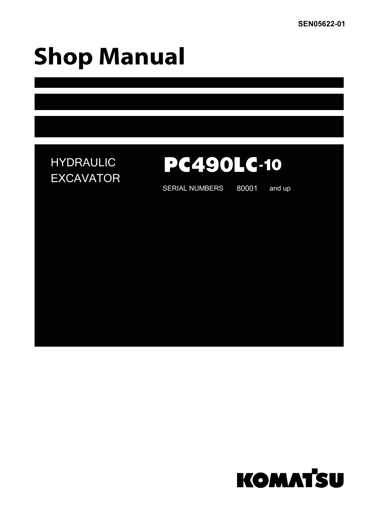
Komatsu PC490LC-10 Hydraulic Excavator Shop Manual SEN05622-01 April 2011 - Complete Workshop Repair & Service Guide — PDF page 1 preview
Komatsu PC490LC-10 Hydraulic Excavator Shop Manual SEN05622-01 April 2011 - Complete Workshop Repair & Service Guide — PDF page 151 preview
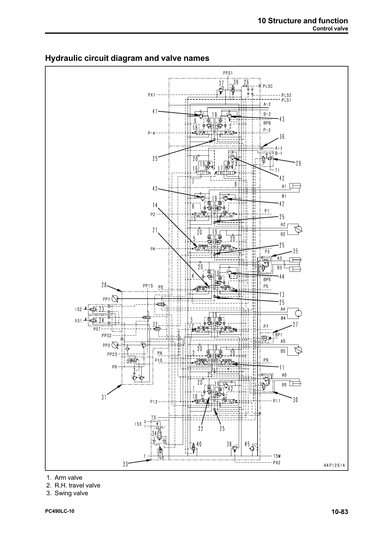
Komatsu PC490LC-10 Hydraulic Excavator Shop Manual SEN05622-01 April 2011 - Complete Workshop Repair & Service Guide — PDF page 1581 preview

Why This Manual Matters for PC490LC-10 Owners and Technicians

The PC490LC-10 is a 46,660 kg class hydraulic excavator powered by the Komatsu SAA6D125E-6 engine, producing 268 kW (359 HP) net at 1,900 rpm. Correct service information is not optional on a machine of this size and complexity. The hydraulic system alone has multiple pressure settings, relief valves, EPC valves, and electronic controls that interact. The engine uses a common rail fuel injection system with precisely matched injectors and an engine controller that must be programmed when components are replaced. The exhaust aftertreatment system (KDPF, KDOC, KCSF) requires specific regeneration and cleaning procedures. Without the correct specifications, a technician can easily set a pressure too high, damage a component through incorrect assembly, or miss a diagnostic step that would have identified a failing sensor. This manual eliminates that risk by giving the exact figures, sequences, and test points that Komatsu specifies for the PC490LC-10.

Instant PDF Delivery – No Shipping, No Waiting

This Komatsu PC490LC-10 Hydraulic Excavator Shop Manual SEN05622-01 is delivered as a PDF download immediately after payment. There is no physical book to ship, no waiting for delivery, and no risk of a damaged or lost parcel. You can open the file on any device – laptop, tablet, or smartphone – and print whichever pages you need for the workshop. Whether you are performing a one-off repair, rebuilding a hydraulic component, tracing an electrical fault, or setting up a maintenance schedule for a fleet of PC490LC-10 machines, this service repair workshop manual provides the complete technical reference in a single, searchable, printable document.

Reviews

There are no reviews yet.

Be the first to review “Komatsu PC490LC-10 Hydraulic Excavator Shop Manual SEN05622-01 April 2011 – Complete Workshop Repair & Service Guide”

What Our Customers Say

★★★★★ Live reviews from customers
Loading customer reviews...
0
    0
    Your Cart
    Your cart is emptyReturn to Shop
    🛒
    Recently Purchased
    🕒 verified order