
Komatsu PC500LC-10M0 & PC500LC-10R Field Assembly Manual GEN00181-03 – PDF Download
Original price was: $79.95.$39.95Current price is: $39.95.
Complete factory-issued field assembly instructions for the Komatsu PC500LC-10M0 and PC500LC-10R hydraulic excavators (document GEN00181-03) – covering chassis, boom, arm, bucket, counterweight, catwalk, flushing, torque tables, sling selection and the final field assembly inspection report.
Description
Komatsu PC500LC-10M0 / PC500LC-10R – Field Assembly Instructions (GEN00181-03)
Every Komatsu PC500LC-10M0 and PC500LC-10R leaves the factory as a set of separated transport units – upper structure with undercarriage, work equipment (boom, arm, bucket, cylinders) and loose assemblies such as the counterweight. This Komatsu PC500LC-10M0 PC500LC-10R field assembly instructions manual, published under document number GEN00181-03, is the official procedure document that tells a field crew how to safely rebuild the machine back to a working excavator. It is written for the work supervisor, crane director, mechanics and assembly operators who handle the machine after shipment, and it delivers the pin-by-pin sequence, the shim calculations, the exact bolt and hose torque values, the greasing points and the air-bleeding steps that a 49-tonne excavator demands.
File Details
- Manual type: Field Assembly Instructions
- Brand: Komatsu
- Models covered: PC500LC-10M0, PC500LC-10M0 SE spec., PC500LC-10R, PC500LC-10R SE spec.
- Engine: KOMATSU SAA6D125E-5
- Document number: GEN00181-03
- Language: English
- File format: PDF
- Page count: 144 pages
Chapters Covered
- A. Assembly of chassis
- B. Assembling of work equipment
- C. Assembling of counterweight and adjustment
- D. Installation of catwalk
- M. Flushing and final checks (M-1 to M-8)
Supporting content includes the tightening torque tables for bolts, pipe threads and hydraulic hose connecting nuts, wire rope and nylon sling selection tables, and the field assembly inspection report.
A. Assembly of Chassis
The opening chapter prepares the undercarriage for work. It covers installation of the track frame steps at the front, rear, left and right positions, the climbing grip and the handrail assemblies (right side first, then left side), plus fitting of the rear-view mirror. The text also carries the safety-meeting requirements the work supervisor must run before any crane or sling work begins, and the reference supervision diagram that assigns roles to the work leader, crane director, operator and mechanics.
B. Assembling of Work Equipment
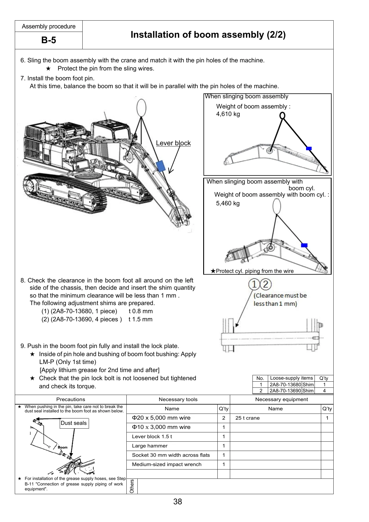
This is the largest section of the PC500LC-10R assembly manual and it runs from B-1 to B-15. It begins with lifting and pinning the boom cylinder foot to the chassis and setting the adjustment shim so the outside clearance stays within 1.5 mm, then releasing the residual pressure in the hydraulic circuit before any hoses are opened. The chapter continues with boom cylinder hose installation, boom cylinder top pin, the boom assembly lift and pin (the boom alone weighs 4,610 kg; with the boom cylinder it reaches 5,460 kg), routing of hoses from the chassis along the top of the boom, boom cylinder head connection, arm assembly installation, bucket cylinder hoses between boom and bucket cylinder, and bucket fitting with the O-ring and shim positions. Later steps cover the work equipment grease piping, work equipment wiring, LED working lamp installation (where fitted) and the two key finishing procedures – greasing after completion of work equipment and bleeding air from the work equipment hydraulic circuit.
C. Assembling of Counterweight and Adjustment
Counterweight work begins with a full track tension test and adjustment procedure: measuring maximum slack with a straight bar placed between idler and carrier roller (standard slack 16 to 34 mm), adding or releasing grease through the tension plug, and the warning that the plug must never be loosened more than one turn. The chapter then covers sticking the sheet to the revolving frame and to the counterweight, rear view mirror installation with the visibility target W = 1 m, camera installation where equipped, and finally the counterweight lift and bolt-up. The counterweight assembly weighs 10,740 kg and its M42 mounting bolts are torqued to 3,430 – 4,212 Nm with a centre value of 3,820 Nm, with shims used only where a clearance or level difference adjustment is unavoidable.
D. Installation of Catwalk
This chapter covers fitting the side step and ladder using plates and bolts, shimming any lean out of the ladder, installing the brackets (five places), and fitting the steps. It also covers the hydraulic tank top handrail – including removal of the tank top cover and transportation bolts first – and the cab top grip installation.
M. Flushing and Final Checks
The closing section of the Komatsu PC500LC-10M0 field assembly instructions handles everything needed before the machine is handed over. It starts by swapping the standard return filter element for the flushing element (absolute filter, mesh size 6 µ), then a structured hydraulic circuit flush: 15 minutes at low idle in neutral, 5 minutes each of bucket, arm and boom cylinder cycling, 3 minutes each direction on swing, and 3 minutes each direction on the left and right travel circuits with the machine jacked on one side. The flushing filter is then replaced with the standard element, oil and coolant levels are checked against the specified capacities, and the manual closes with the parts to be touched up after field assembly and the KomVision camera calibration and 12 m visibility check sequence. An error-code check step and the field assembly inspection report round the document off.
Torque, Sling and Inspection Reference Content
Unlike a general operator booklet, this Komatsu PC500LC-10R field assembly instructions PDF contains the actual numerical data the field crew needs on the job. The bolt tightening tables run from M6 × 1 (12 Nm) through M39 × 3 (2,940 Nm), split into a target value and a range. Pipe-thread torque is handled separately for mild steel / cast iron male screws and for refined heat-treated steel. Hydraulic hose connecting nuts are torqued by hose outside diameter and seal type – face seal (O-ring) or taper seal – with widths across flats listed alongside. Separate socket size tables for M39 and larger bolts are provided. Wire rope selection is presented as a table under B 8817-1991 using 6 × 24 type rope slings, with 90°/45°/30° sling angle columns and 1-pc and 2-pc configurations. A nylon sling selection table gives rated loads for vertical, choker, basket and 2-sling basket hitches across 25 mm to 300 mm wide slings.
Specifications at a Glance
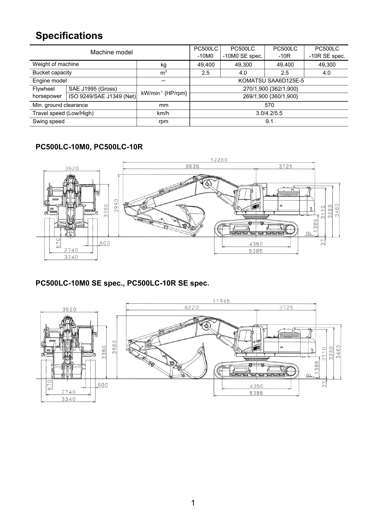
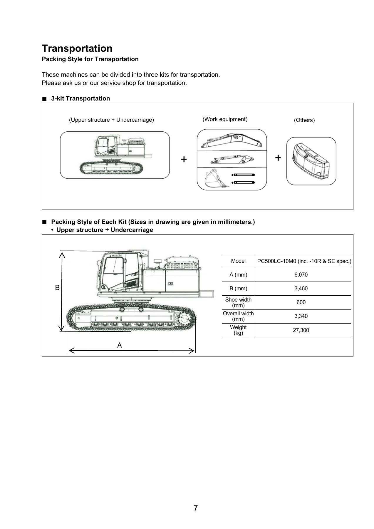
The machine weight for the PC500LC-10M0 and PC500LC-10R is listed at 49,400 kg with a 2.5 m³ bucket or 49,300 kg with a 4.0 m³ bucket. Minimum ground clearance is 570 mm. Travel speed is 3.0 / 4.2 / 5.5 km/h in low / mid / high, and swing speed is 9.1 rpm. Flywheel horsepower for the SAA6D125E-5 is 270 kW / 1,900 rpm gross (362 HP) and 269 kW / 1,900 rpm net (360 HP). Transport dimensions for the packed upper structure plus undercarriage are 6,070 mm × 3,460 mm, with an overall width of 3,340 mm on 600 mm shoes. The counterweight alone is 10,740 kg, the boom 4,600 kg STD / 4,525 kg SE spec., the arm 2,775 kg STD / 2,690 kg SE spec., and the boom cylinder 422 kg.
Why This Field Assembly Manual Matters in the Field
Assembling a large excavator from transport units is not a job to be improvised. A boom foot pin that is pushed in without LM-P on the first fit, a shim pack left out of the boom foot, a hydraulic hose torqued without checking the O-ring seat, or a counterweight bolt torqued to the wrong end of its range can all lead to premature pin galling, hydraulic contamination, cracked mirror brackets or – worst case – a counterweight separating from the revolving frame. This Komatsu PC500LC-10M0 PC500LC-10R assembly manual gives the exact clearances, shim thicknesses (0.8 mm and 1.5 mm options), greasing sequences and torque ranges that the factory specifies for each of those joints, so the rebuilt machine performs as intended rather than simply running.
The flush procedure alone is a reason to keep this document on hand. The manual makes it clear that the standard return filter must be replaced with a 6-micron absolute flushing element before the circuit is operated, that full stroke on any cylinder may damage the element while the filter relief is closed, and that the flushing element must be discarded after use and never reused. Getting that sequence right is the difference between a clean hydraulic system and a pump full of transport debris.
IMAGES PREVIEW
Instant PDF Delivery
This Komatsu PC500LC-10R field assembly instructions file is supplied as an instant-download PDF – no shipping, no waiting for a paper copy. Open it on a laptop in the workshop office, on a tablet at the machine, or print the pages you need and take them into the field. Whether you are the dealership technician assembling a new delivery, a rental fleet mechanic rebuilding a machine after transport, or a workshop preparing a detailed assembly plan for a customer machine, the GEN00181-03 field assembly manual gives you the procedure, the values and the inspection checklist to do the job to Komatsu’s field standard.

Reviews
There are no reviews yet.