★ TRUSTED BY 321,897+ PROFESSIONALS WORLDWIDE
🏒
Trusted Business
Verified & Licensed
πŸ›‘οΈ
Virus Free Files
100% Safe Downloads
πŸ”’
Secure Payment
SSL Protected
⚑
Instant Delivery
Available Immediately
Sale!

Komatsu PC5500-6 Hydraulic Mining Shovel Troubleshooting Manual TS 15110-xD-GB-0 – PDF

Original price was: $44.95.Current price is: $27.95.

Complete 550-page English troubleshooting manual for the Komatsu PC5500-6 hydraulic mining shovel (serial 15110 / 15100 and up). Covers G-code fault diagnosis, symptom-based troubleshooting, CAN-bus and node output references, wiring diagrams, standard electrical value tables, and component locations.

⚑
Instant PDF Download
Available immediately
πŸ’Ύ
Save to Your Device
Download & keep forever
πŸ›‘οΈ
Antivirus Scanned
100% virus-free
🌍
Trusted Worldwide
175,000+ customers

Description

Komatsu PC5500-6 Hydraulic Mining Shovel Troubleshooting Manual – TS 15110-xD-GB-0

This is the complete Komatsu troubleshooting manual for the PC5500-6 hydraulic mining shovel, published under document number TS 15110-xD-GB-0 and covering machines from serial number 15110 (15100) upward. It runs 550 pages and is written entirely in English. Rather than a general service overview, this is a diagnostic-focused troubleshooting manual – it assumes the shovel is in service and something has gone wrong, and it walks the technician through locating, confirming, and correcting the fault using Komatsu’s own G-code system, KOMTRAX Plus monitor screens, MTC and CAN-node diagnostics, and circuit wiring diagrams.

The Komatsu PC5500-6 troubleshooting manual is built for practical use in the field. Every troubleshooting chart is written around a specific displayed trouble code or a specific reported symptom, so the technician is never left guessing where to start. Wiring diagram pages for individual circuits are embedded directly into the relevant troubleshooting chart, alongside photographs and illustrations of the MTC, ICN-D and ICN-V nodes, sensors, control and filter panels, and hydraulic oil tank components.

File Details

  • Manual type: Troubleshooting Manual
  • Brand: Komatsu (Komatsu Mining Germany GmbH)
  • Model: PC5500-6 Hydraulic Mining Shovel
  • Document number: TS 15110-xD-GB-0
  • Serial number coverage: 15110 (15100) and up
  • Language: English
  • Page count: 550 pages
  • File format: PDF

Chapters Covered

  • Safety – Safety Information, Overview (Normal Operations, Regular Maintenance, Troubleshooting/Adjustments/Repair), Sound Pressure Level in the Operator’s Cab, General Precautions Common to Operation, Additional Safety Information for Troubleshooting and Adjustments, Special Safety Equipment (FOPS, Safety Harness to EN 361, warning beacon)
  • Introduction & General Information for Troubleshooting – Overview, General Precautions, Preparations for Work, Fundamental Requirements for Troubleshooting (technical documentation, tools, personnel), Sequence of Events in Troubleshooting, Handling of Electric Equipment and Hydraulic Components, General Working Procedures (air bleeding, cylinder bypass test), Information About MTC & Nodes (ICN-D, ICN-V, DIP switches), Basics About “How to Crimp”, Cable Shielding
  • Mounting Locations and Connector Types – Component Location (superstructure, machine house, engines, engine remote oil tank sensors, suction oil manifold, control and filter panels, remote control valves, hydraulic oil tank, lubrication stations, cab base, emergency shutdown switches, access ladder, service arm), Connector Types Overview
  • Standard Value Table for Electrical Components
  • References for Troubleshooting (CAN Bus & Node Outputs) – CAN-Bus Trouble or Node Output Trouble, Trouble CAN-Bus or CAN-Hardware (G00308), Trouble Output Short-Circuit (G00043), Sequence of the CAN Nodes, Troubleshooting for Relay Monitored Node Outputs (Relay Check, Output Check)
  • Tables for Testing and Troubleshooting – PT100 Temperature Sensor Test Value Tables (Centigrade-Volt and Centigrade-Ohm), Table of Trouble Codes (G-Codes), Table of Instruction Messages, Table of Binary Codes, Table of Add-On Binary Codes for G00308, Binary Output Signals on the KOMTRAX Plus Monitor, Tables of Symptom Codes (Engines, Hydraulic System, Mechanical System, Additional Systems), Power Supply, Cable Colour Identification
  • Troubleshooting by Trouble Code – individual G-code charts (G00001 through G00491), including Shut-Off gate valve, pump controller, hydraulic oil level and temperature, gear lubrication (PTO 1 / PTO 2), starter control, emergency safety circuit, battery voltage and charging current, X1 / X2 / X4 pressures, fuel level, air cleaners, lubrication systems, CAN-bus, ladder and service arm relays, software compatibility and communication faults
  • Troubleshooting by Symptoms – Engine symptoms (SEL001-SEL012), Hydraulic system symptoms (SHY001-SHY018), Mechanical system symptoms (SME001-SME010), Additional system symptoms (SAD001-SAD004)

In total, the manual gives the technician two complementary ways of locating a fault on this specific machine. When the monitoring and control system has caught the problem and set a fault code, the G-code chapter takes over. When the problem is felt before it is flagged – slow boom-up, excessive swing overrun, black exhaust, a warm hydraulic cylinder, a noisy PTO – the symptom chapter provides the judgment tables and step-by-step checks. Between those two routes, the standard value tables, CAN-bus references, and component location chapters supply the raw measurement data and the physical place on the machine where each test is performed.

What You Can Do With This Manual

Diagnosing faults from the KOMTRAX Plus monitor and the MTC is one of the manual’s strongest uses. Trouble codes and instruction messages are listed with their colour codes, acoustic signals, memory behaviour, and the resulting machine behaviour, so an operator-reported message can be translated quickly into a concrete test path. For each affected code, the troubleshooting chart names the suspect components, the connector and pin numbers, and the expected readings at the T-box or REAL TIME MONITOR – the technician is told what a healthy reading looks like before anything is disconnected.

Electrical work on the PC5500-6 depends on the connectors and nodes being handled correctly. This manual documents the MTC connector layout, the ICN-D and ICN-V node connector arrangements, the DIP switch settings for node number and CAN bus baud rate, and the Deutsch crimping procedure – including the HDT 48 tool setup and the accepted crimp appearance. Standard resistance and voltage values are tabulated per component: fuel shut-off solenoids, engine speed sensors, pre-lube oil pressure switches, cold start aid solenoids, air filter clogging switches, PT100 temperature sensors, pressure transducers and switches, hydraulic oil level sensors, proportional and directional solenoid valves, remote control valves, pedal and lever sensors, and the CAN bus termination resistors.

Hydraulic and mechanical troubleshooting is equally detailed. Cylinder bypass testing with an infrared thermometer is described with the expected temperature rise that identifies a leaking seal package. Pressure adjustment procedures and target values for X1-1, X1-2, X2 and X4 circuits appear alongside the corresponding fault codes. PTO gear oil, hydraulic oil, and fan drive solenoid valve checks are covered, as are the lubrication systems – CLS1, CLS2 and SLS – including the sonar and binary grease level sensors, the vent valves, and the end-of-line pressure switches that control the lube cycle.

Who This Manual Suits

This troubleshooting manual is written for Komatsu-trained service personnel and for the maintenance teams responsible for keeping a PC5500-6 hydraulic mining shovel productive. It assumes the reader has access to the machine’s wiring diagrams and the Operation & Maintenance Manual, since those documents are referenced throughout for adjustment procedures, oil specifications, and safety notes. It is not a beginner’s guide to heavy equipment – it is a fault-location document for someone already familiar with hydraulic mining shovels and comfortable working from KOMTRAX Plus service screens.

Because the same fault code can be triggered by several different components, the manual’s value lies in narrowing those possibilities quickly. The cross-referencing between the CAN-bus sequence chapter, the relay-monitored node output checks, and the individual G-code charts means the technician can move from a displayed message to the failing node, connector, or sensor without dismantling the machine speculatively.

Complete PDF Bookmark Tree

Complete Bookmarks

The complete bookmarks in the β€œKomatsu PC5500-6 Hydraulic Mining Shovel Troubleshooting Manual TS 15110-xD-GB-0 – PDF” are as follows:

Front coverp. 1
Table of Contentsp. 3
1 SAFETYp. 21
1.1 SAFETY INFORMATIONp. 22
1.2 OVERVIEWp. 23
1.2.1 NORMAL OPERATIONSp. 23
1.2.2 REGULAR MAINTENANCEp. 23
1.2.3 TROUBLESHOOTING, ADJUSTMENTS AND REPAIRp. 23
1.2.4 ADDITIONAL SAFETY PRECAUTIONS FOR ASSEMBLING, DISASSEMBLING AND TRANSPORTATION OF THE EXCAVATORp. 23
1.3 SOUND PRESSURE LEVEL IN THE OPERATOR’S CAB.p. 24
1.4 GENERAL PRECAUTIONS COMMON TO OPERATION ON THE EXCAVATORp. 25
1.4.1 UNDERSTANDING THE MACHINEp. 25
1.4.2 PRECAUTIONS BEFORE STARTING OPERATION ON THE EXCAVATORp. 25
1.4.2.1 ENSURING SAFE OPERATIONp. 25
1.4.3 PREPARATIONS FOR SAFE OPERATIONp. 25
1.4.3.1 PRECAUTIONS REGARDING SAFETY RELATED EQUIPMENTp. 25
1.4.3.2 INSPECTING THE MACHINEp. 25
1.4.3.3 WEAR WELL FITTING CLOTHES AND PROTECTIVE EQUIPMENTp. 26
1.4.3.4 KEEP MACHINE CLEANp. 26
1.4.3.5 PRECAUTIONS INSIDE OPERATOR’S COMPARTMENTp. 26
1.4.3.6 PROVIDE FIRE EXTINGUISHER AND FIRST AID KITp. 27
1.4.3.7 IF A PROBLEM IS FOUNDp. 27
1.4.4 FIRE PREVENTIONp. 27
1.4.4.1 PRECAUTIONS TO PREVENT FIREp. 27
1.4.4.2 ACTION IF FIRE OCCURSp. 28
1.4.4.3 EMERGENCY EXIT FROM OPERATOR’S CABp. 29
1.4.5 PRECAUTIONS WHEN GETTING ON OR OFF THE MACHINEp. 29
1.4.5.1 USE HANDRAILS AND STEPS WHEN GETTING ON OR OFF THE MACHINEp. 29
1.4.5.2 NO JUMPING ON OR OFF THE MACHINEp. 29
1.4.5.3 NO PEOPLE ON THE ATTACHMENTp. 29
1.4.5.4 WORKING IN HIGH PLACESp. 29
1.4.5.5 LEAVING OPERATOR’S SEAT WITH LOCKp. 30
1.4.5.6 LEAVING THE MACHINEp. 30
1.4.6 BURN PREVENTIONp. 31
1.4.6.1 Hot coolantp. 31
1.4.6.2 Hot oilp. 31
1.4.7 PRECAUTIONS WHEN CLEANING CAB GLASSp. 31
1.4.8 PRECAUTIONS RELATED TO PROTECTIVE STRUCTURESp. 32
1.4.8.1 UNAUTHORIZED MODIFICATIONp. 32
1.4.8.2 PRECAUTIONS RELATED TO ATTACHMENTS AND OPTIONSp. 32
1.4.9 ELECTROMAGNETIC COMPATIBILITY (EMC)p. 33
1.4.10 PRECAUTIONS AT JOBSITEp. 34
1.4.10.1 VISIBILITY FROM OPERATOR’S SEATp. 35
1.4.10.2 CAMERA SYSTEM WITH MONITORSp. 35
1.4.10.3 ENSURE GOOD VISIBILITYp. 35
1.4.10.4 CHECKING SIGNS AND SIGNALMAN’S SIGNALSp. 35
1.4.10.5 INVESTIGATE AND CONFIRM JOBSITE CONDITIONSp. 36
1.4.10.6 DO NOT GO CLOSE TO HIGH VOLTAGE CABLESp. 36
1.4.10.7 WORKING ON LOOSE GROUNDp. 37
1.4.10.8 GAS, DUST, STEAM AND SMOKEp. 37
1.4.10.9 VENTILATION OF ENCLOSED AREASp. 38
1.4.11 STARTING motorp. 39
1.4.11.1 WARNING TAGp. 39
1.4.11.2 CHECKS BEFORE STARTING motorp. 39
1.4.11.3 PRECAUTION WHEN STARTING motorp. 39
1.4.11.4 PRECAUTION IN COLD AREASp. 40
1.4.12 OPERATIONp. 40
1.4.12.1 CHECKS BEFORE OPERATIONp. 40
1.4.12.2 PRECAUTIONS WHEN TRAVELLING IN FORWARD OR REVERSEp. 41
1.4.12.3 PRECAUTIONS WHEN travellingp. 42
1.4.12.4 TRAVELLING ON SLOPESp. 43
1.4.12.5 OPERATIONS ON SLOPESp. 44
1.4.12.6 PROHIBITED OPERATIONSp. 44
1.4.12.7 TRAVELLING ON FROZEN OR SNOW COVERED SURFACESp. 45
1.4.12.8 PARKING THE MACHINEp. 45
1.4.12.9 TRANSPORTATIONp. 45
1.5 PRECAUTION FOR MAINTENANCEp. 46
1.5.1 GENERAL PRECAUTIONSp. 46
1.5.1.1 SELECTION AND QUALIFICATION OF PERSONNEL – BASIC RESPONSIBILITIESp. 47
1.5.1.2 STOP motor FOR MAINTENANCEp. 48
1.5.1.3 WARNING TAGp. 49
1.5.1.4 KEEP WORKPLACE CLEAN AND TIDYp. 50
1.5.1.5 APPOINT LEADER WHEN WORKING WITH OTHERSp. 50
1.5.1.6 TWO WORKERS FOR MAINTENANCE WHEN THE MACHINE IS RUNNINGp. 51
1.5.1.7 INSTALLING, REMOVING OR STORING ATTACHMENTSp. 51
1.5.1.8 PRECAUTIONS WHEN WORKING UNDER THE MACHINE OR EQUIPMENTp. 52
1.5.1.9 NOISEp. 52
1.5.1.10 WHEN USING A HAMMERp. 52
1.5.1.11 PROPER TOOLSp. 53
1.5.1.12 ACCUMULATORp. 53
1.5.1.13 PERSONNELp. 53
1.5.2 PRECAUTIONS FOR INSPECTION AND MAINTENANCEp. 54
1.5.2.1 PRECAUTION WHEN WELDINGp. 54
1.5.2.2 BATTERY HANDLINGp. 54
1.5.3 PRECAUTIONS WITH HIGH PRESSURE FLUIDp. 55
1.5.3.1 PRECAUTIONS WITH HIGH FUEL PRESSUREp. 55
1.5.3.2 HANDLING HIGH PRESSURES HOSES OR PIPESp. 56
1.5.3.3 REPLACEMENT OF HOSE LINESp. 56
1.5.3.4 INSPECTION OF HOSE LINESp. 56
1.5.3.5 PERIODIC REPLACEMENT OF SAFETY CRITICAL PARTSp. 57
1.5.3.6 PRECAUTIONS FOR HIGH VOLTAGEp. 57
1.5.3.7 AIR CONDITIONING MAINTENANCEp. 57
1.5.3.8 COMPRESSED AIRp. 58
1.5.3.9 WASTE MATERIALSp. 58
1.6 ADDITIONAL SAFETY INFORMATION FOR TROUBLESHOOTING AND ADJUSTMENTSp. 59
1.6.1 INSPECTION OF THE HYDRAULIC SYSTEMp. 59
1.6.2 TWO WORKERS ONLY WHEN THE MACHINE IS RUNNING DURING ADJUSTMENTSp. 59
1.6.3 AREAS OF POTENTIAL DANGER AROUND THE EXCAVATORp. 59
1.7 SPECIAL SAFETY EQUIPMENTp. 60
1.7.1 FRONT GUARD PROTECTIVE STRUCTUR ’FOPS’ FOR OPERATOR’S CABp. 61
1.7.2 OBJECT HANDLINGp. 61
1.7.3 LIGHTINGp. 61
1.7.4 WARNING BEACONp. 61
1.7.5 SAFETY HARNESS IN CONFORMITY WITH EN 361 (EUROPEAN STANDARD)p. 61
1.7.5.1 SAFETY HARNESS IN CONFORMITY WITH EN 361 (EUROPEAN STANDARD)p. 61
1.7.5.2 INSTRUCTIONS FOR USEp. 63
1.7.5.3 PRIOR TO USING THE HARNESS (1), THE WEARER SHALLp. 65
1.7.5.4 RECOMMENDATIONS FOR USE OF THE HOLDING HOOKS AND HOLD- BACK HOOKS OF THE SAFETY HARNESS (1),p. 65
1.7.5.5 INSTRUCTIONS FOR USEp. 67
2 Introduction & general information for troubleshootingp. 69
2.1 Overviewp. 70
2.1.1 General advice when using troubleshooting chartsp. 70
2.2 General precautionsp. 71
2.3 Preparations for workp. 72
2.4 Precautions during workp. 72
2.5 Precautions when carrying out any operationp. 73
2.5.1 precautions when carrying out removal workp. 73
2.5.2 Precautions when carrying out installation workp. 73
2.5.3 Precautions when completing the operationp. 74
2.6 Fundamental requirements for troubleshootingp. 75
2.6.1 Technical documentationp. 75
2.6.2 Toolsp. 75
2.6.2.1 Reference guide for deutsch removal toolsp. 78
2.6.3 Personnelp. 79
2.7 Points to remember when trouble- shootingp. 79
2.8 Sequence of events in troubleshootingp. 81
2.9 Checks before troubleshootingp. 82
2.10 Handling of electric equipment and hydraulic componentsp. 83
2.10.1 Points to remember when handling electric equipmentp. 83
2.10.2 Points to remember when handling hydraulic equipmentp. 86
2.11 General working proceduresp. 88
2.11.1 Air bleeding of various yydraulic partsp. 88
2.11.2 Air bleeding from the hydraulic pumpsp. 88
2.11.3 Air bleeding from the hydraulic cylindersp. 88
2.12 Cylinder bypass testp. 89
2.13 Information about MTC & nodesp. 90
2.13.1 Outline of the MTC and its connector locationsp. 90
2.13.1.1 View onto the MTC connectors* LH & RHp. 90
2.13.1.2 General description of the MTCp. 90
2.13.1.3 Information about the LED indications at the MTCp. 91
2.13.2 Information about the ICN-D nodep. 91
2.13.2.1 View onto an ICN-D node without wiringp. 92
2.13.2.2 View onto the status LEDs at the ICN-D nodep. 93
2.13.2.3 General information on the LED controlp. 93
2.13.3 Information about the ICN-V nodep. 95
2.13.3.1 View onto an ICN-V nodep. 95
2.13.3.2 View onto an open ICN-V node and its DIP-switchesp. 96
2.13.4 DIP switches at the ICN-D and ICN-V nodesp. 97
2.14 Basics about "how to crimp"p. 98
2.14.1 Stripping a wire for use with the HDT 48 crimp toolp. 98
2.14.2 View onto the Deutsch crimp tool HDT 48p. 98
2.14.3 Adjustment of the wire size at the Deutsch crimp tool HDT 48p. 99
2.14.3.1 Wire cross section units in mm2 and AWGp. 99
2.14.4 Crimping instructions (for Deutsch crimp tool HDT 48)p. 100
2.15 Cable shieldingp. 101
3 Mounting locations and connector typesp. 103
3.1 Component locationp. 104
3.1.1 View onto the superstructurep. 104
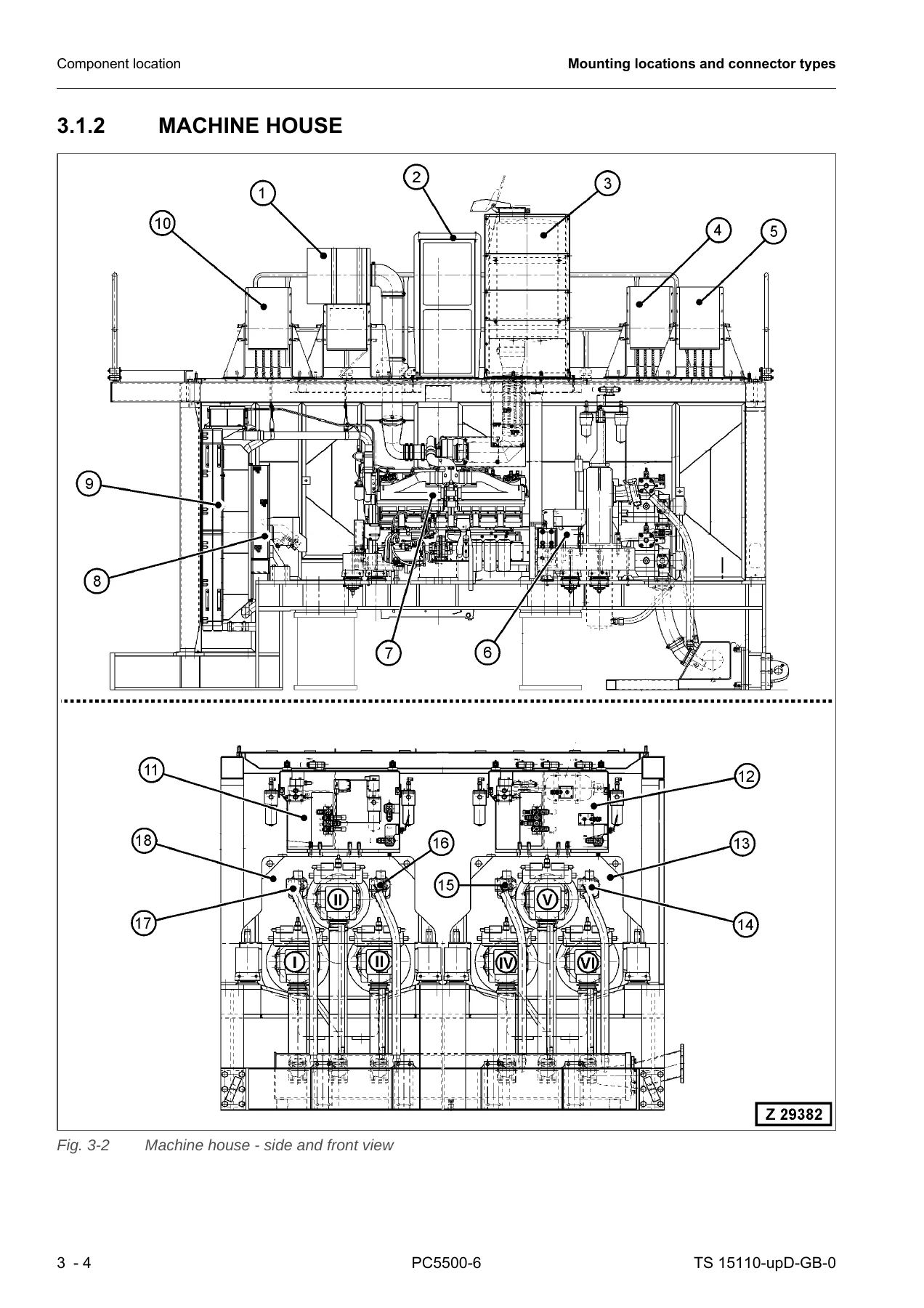
3.1.2 Machine housep. 106
3.1.3 Location of the electrical parts on the enginesp. 108
3.1.4 Location of engine remote oil tank sensorsp. 110
3.1.5 Suction oil manifold with strainersp. 112
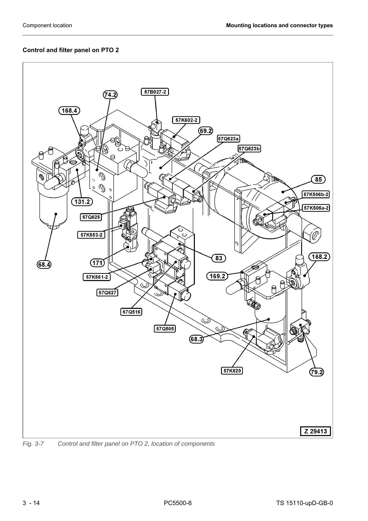
3.1.6 Control and filter panels – location of componentsp. 114
3.1.7 Location of the remote control valvesp. 118
3.1.8 Hydraulic oil tank – location of electrical componentsp. 120
3.1.9 CLS1/2 & SLS lubrication station and the lubrication cycle componentsp. 122
3.1.10 Electrical components in the cab basep. 124
3.1.11 Emergency shutdown switches & safety switch for maintenancep. 128
3.1.12 Hydraulically operated access ladderp. 130
3.1.13 Service armp. 132
3.2 Connector types overviewp. 134
4 Standard value table for electrical componentsp. 139
5 References for Troubleshooting (CAN Bus & Node Outputs)p. 151
5.1 CAN-Bus trouble or Node Output Troublep. 152
5.1.1 Trouble CAN-BUS or CAN-Hardware (G00308)p. 153
5.1.2 Trouble output short-circuit (G00043)p. 154
5.2 Sequence of the CAN nodes at the CAN busp. 156
5.3 Troubleshooting for Relay Monitored Node Outputsp. 157
5.3.1 Relay Checkp. 157
5.3.1.1 G00107 – Trouble slew parking brake control 56K250a G00109 – Trouble slew parking brake control 56K250bp. 158
5.3.2 Output Checkp. 162
5.3.2.1 G00108 – Trouble slew parking brake control Output to 56K250a G00110 – Trouble slew parking brake control Output to 56K250bp. 163
6 Tables for testing and troubleshootingp. 167
6.1 Test value table for temperature sensors (PT100) g Centigrade – Voltp. 168
6.2 Test Value Table for Temperature Sensors (PT100) g Centigrade – Ohmp. 169
6.3 Table of trouble codes (G-Codes)p. 170
6.4 Table of instruction messagesp. 177
6.5 Table of binary codesp. 180
6.5.1 Table of Add-On binary codes for G00308p. 182
6.6 Binary Output Signals on the KOMTRAX Plus Monitorp. 183
6.7 Tables of Symptom Codesp. 186
6.7.1 Symptoms of the Engines and Related Electrical Systemsp. 186
6.7.2 Symptoms of the Hydraulic Systemp. 186
6.7.3 Symptoms of the Mechanical Systemp. 187
6.7.4 SYMPTOMS OF ADDITIONAL SYSTEMSp. 187
6.8 Power Supplyp. 188
6.9 Cable colour identificationp. 188
7 Troubleshooting by trouble codep. 189
G00001 – Trouble Shut-Off (gate) valvep. 190
View onto the gap of proximity switch 40B031p. 192
Input signal (analog) of the proximity switch 40B031 on the REAL TIME MONITORp. 193
View onto the setting for SHUTDOWN BYPASS on the KOMTRAX Plus monitorp. 193
Wiring diagram (40B031) for trouble code G00001 (Trouble Shut-Off (gate) valve)p. 194
G00002 – Test speed 1800 1/min engine 1p. 195
Wiring diagram (11S041-1 & 11S041-2) for trouble codes G00002 & G00006p. 196
G00003 – Trouble pump controllerp. 197
G00005 – Low hydraulic oil levelp. 203
Wiring diagram, oil level label, and defined position of the attachment (G00005)p. 205
G00006 – Test speed 1800 1/min engine 2p. 206
G00007 – Trouble hydraulic oil levelp. 206
Wiring diagram (40B004) and the defined position of the attachment (G00007)p. 207
G00012 – Central lubrication system grease level too lowp. 208
G00013 – Slew ring gear lubr. system grease level too lowp. 208
Troubleshooting for sonar type grease level sensorsp. 208
Troubleshooting for binary type grease level sensorsp. 212
Wiring diagram (sonar type sensors) for trouble codesG00012 / G00013 / G00202p. 215
Wiring diagram (sonar sensor junction box) for trouble codes G00012 / G00013 / G00202p. 216
Wiring diagram (binary type sensors) for trouble codesG00012 / G00013 / G00202p. 217
Wiring diagram (binary sensor junction box) for trouble codes G00012 / G00013 / G00202p. 218
G00020 – Trouble Shut-Off (gate) valve (Start blocked)p. 219
View onto the gap of proximity switch 40B031 (G00020)p. 221
Wiring diagram (40B031) for trouble code G00020 (Main gate valve closed)p. 222
Input signal (analog) of the proximity switch 40B031 on the REAL TIME MONITORp. 223
View onto the setting for SHUTDOWN BYPASS on the KOMTRAX Plus monitorp. 223
G00031 – Set engine to low idlep. 224
Wiring diagram (20S030) for trouble code G00031p. 225
Input signal of the engine speed switch 20S030 on the REAL TIME MONITORp. 225
G00032 – Trouble starterp. 226
Wiring diagram (Cold Start Signal Engine 1 & 2) for trouble code G00032p. 227
Wiring diagram ("Engine running" signals) for trouble code G00032p. 228
G00033 – Trouble KOMTRAX Plus controllerp. 229
G00034 – Trouble KOMTRAX Plus displayp. 230
G00035 – Trouble totally loss gear oil (PTO 1)p. 231
G00036 – Trouble totally loss gear oil (PTO 2)p. 231
View onto the location of sensor 57B175-1/-2 at the PTO1/2 (G00035)p. 233
Input signal (analog) of the gear oil sensors 57B175-1/-2 on the REAL TIME MONITORp. 234
View onto the setting for SHUTDOWN BYPASS on the KOMTRAX Plus monitorp. 234
Wiring diagram (57B175-1/-2) for trouble codes G00035 & G00036p. 235
G00037 – Trouble monitoring, engine 2 speed too lowp. 236
G00038 – Trouble monitoring, engine 2 speed too highp. 236
G00039 – Actuate engine speed selector switchp. 236
G00043 – Trouble output short-circuitp. 237
G00048 – Trouble emergency safety circuitp. 238
Wiring diagram (11K044a) for trouble code G00048p. 239
G00053 – Reset emergency safety circuitp. 240
G00054 – Monitoring idle position cut offp. 241
Wiring diagram (11K032) for trouble code G00054p. 242
Input signal (analog) of relay 11K032 on the REAL TIME MONITOR (G00054)p. 243
Exemplary view onto the KOMTRAX Plus Failure History (G00054)p. 243
G00060 – Fire in the power housep. 244
Wiring diagram (fire alarm) for trouble code G00060p. 246
Wiring diagram (10B350 in the safety circuit) for G00060p. 247
G00061 – Trouble monitoring, engine 1 speed too lowp. 248
Input signal (analog) of 51K003b-1 & 51K003b-2 on the REAL TIME MONITORp. 250
Wrong signal of the engine 2 speed converter on the REAL TIME MONITORp. 250
Wiring diagram (engine speed) for trouble codes G00061 & G00037p. 251
G00062 – Trouble monitoring, engine 1 speed too highp. 252
Wiring diagram (engine speed) for trouble codes G00062 & G00038p. 253
G00063 – Trouble monitoring hydraulic oil tempp. 254
Wiring diagram (59B015) for trouble code G00063p. 255
G00064 – Trouble monitoring hydraulic oil levelp. 256
Wiring diagram (40B004) for trouble code G00064p. 258
G00065 – Very low hydraulic oil levelp. 259
View onto the hydraulic oil level labelp. 259
G00066 – Trouble hydraulic oil temperaturep. 260
Hydraulic oil temperature tablep. 261
Wiring diagram (57K506a-1/57K506b-1 & 57K506a-2/57K506b-2) and location for G00066p. 262
G00067 – Trouble battery voltage too highp. 263
Wiring diagram (11T080) and component location for G00067p. 264
Input signal of 11T080 on the REAL TIME MONITOR for G00067p. 265
G00068 – Trouble gear lubrication (PTO 2)p. 266
G00069 – Trouble monitoring oil temperature gear (PTO 1)p. 267
Input of 57B049-1 on the REAL TIME MONITOR (G00069)p. 268
Gear oil temperature (PTO 1 & PTO 2) on the Main Gauge Screenp. 268
Wiring diagram (57B049-1 & 57B049-2) and component location (G00069 & G00083)p. 269
G00070 – Trouble oil temperature gear (PTO 1)p. 270
PTO gear oil settings (oil type and viscosity)p. 272
Location of the PTO gear oil level dipstick & temperature sensors 57B049-1/57B049-2p. 273
G00071 – Trouble gear lubrication (PTO 1)p. 274
Wiring diagram (57B017-1 & 57B017-2) for trouble codes G00071 & G00068p. 275
G00081 – Trouble lubrication systemp. 276
Wiring diagram (11K050) for trouble code G00081p. 277
Operation cycles of the lubrication systemsp. 278
G00083 – Trouble monitoring oil temperature gear (PTO 2)p. 279
G00084 – Trouble oil temperature gear (PTO 2)p. 279
G00086 – SHUTDOWNp. 279
G00087 – Stop all movements for low idlep. 280
G00090 – Trouble power supplyp. 281
Wiring diagram (stabilized power supply) for G00090 & G00099p. 282
G00091 – Pilot control cut outp. 283
View onto the lock lever and the cover of 20S105 (G00091)p. 284
G00092 – Emergency shut-down at access ladderp. 285
G00093 – Emergency shut-down at valve blockp. 285
G00094 – Emergency shut-down at hydraulic control panelp. 285
G00095 – Emergency shut-down in cabinp. 285
Wiring diagram (emergency switches) for G00092~G00095 & G00097p. 287
G00096 – Pilot control cut outp. 288
Wiring diagram (20S094) for trouble code G00096p. 289
G00097 – Emergency shut-down at counterweightp. 290
G00099 – Trouble power supplyp. 290
G00100 – Maintenance Safety Switchp. 290
Wiring diagram (50S058) for trouble code G00100p. 291
G00103 – Faulty switch 20M004p. 292
Wiring diagram 1 (windscreen wiper) for trouble code G00103p. 294
Wiring diagram 2 (windscreen wiper) for trouble code G00103p. 295
G00104 – Trouble battery currentp. 296
Wiring diagram (battery current) for trouble code G00104p. 298
G00105 – Trouble battery charging current too lowp. 299
Wiring diagram (11T080) for trouble code G00105p. 300
G00107 – Trouble slew parking brake control 56K250ap. 301
View onto the CoDeSys HMI Visualization screen for trouble code G00107p. 303
Wiring diagram (56K250a & 56K250b) for trouble code G00107p. 304
G00108 – Trouble slew parking brake control Output to 56K250ap. 305
View onto the CoDeSys HMI Visualization screen for trouble code G00108p. 307
Wiring diagram (56K250a & 56K250b) for trouble code G00108p. 308
G00109 – Trouble slew parking brake control 56K250bp. 309
G00110 – Trouble slew parking brake control Output to 56K250bp. 309
G00111 – Trouble travel parking brake control 56K251ap. 309
56K251a & 56K251b (relay check) on the REAL TIME MONITOR (G00111 & G00113)p. 309
G00112 – Trouble travel parking brake control Output to 56K251ap. 310
56K251a & 56K251b (output check) on the REAL TIME MONITOR (G00112 & G00114)p. 310
G00113 – Trouble travel parking brake control 56K251bp. 311
G00114 – Trouble travel parking brake control Output to 56K251bp. 311
G00115 – Trouble slew hydraulic brake control 56K252ap. 311
56K252a & 56K252b (relay check) on the REAL TIME MONITOR (G00115 & G00117)p. 311
G00116 – Trouble slew hydraulic brake control Output to 56K252ap. 312
56K252a & 56K252b (output check) on the REAL TIME MONITOR (G00116 & G00118)p. 312
G00117 – Trouble slew hydraulic brake control 56K252bp. 313
G00118 – Trouble slew hydraulic brake control Output to 56K252bp. 313
G00139 – Trouble monitoring X1-2 pressurep. 313
G00140 – Trouble monitoring X1-1 pressurep. 313
Wiring diagram (57B085-1 & 57B085-2) for trouble codes G00140 & G00139p. 315
G00141 – Trouble monitoring X2 pressurep. 316
Wiring diagram (57B086) for trouble code G00141p. 318
G00142 – Trouble monitoring pump support pressure X4-1p. 319
Input signal of 57B097-1 & 57B097-2 on the REAL TIME MONITOR for G00142 & G00196p. 321
Wiring Diagram (57B097-1 & 57B097-2) for G00142 & G00196p. 322
G00147 – Trouble monitoring gear lubrication (PTO 1)p. 323
Wiring diagram (57B017-1 & 57B017-2) for trouble codes G00147 & G00150p. 326
G00148 – Trouble monitoring fuel levelp. 327
Wiring diagram (31B063) for G00148p. 329
G00150 – Trouble monitoring gear lubrication (PTO 2)p. 330
G00151 – Trouble monitoring gear (PTO) oil filter 1p. 330
Wiring diagram (57B027-1/-2) and component location for G00151 & G00193p. 333
G00154 – Trouble monitoring return oil filterp. 334
Wiring diagram (40B163) for trouble code G00154p. 336
G00155 – Trouble monitoring leak oil filterp. 337
Wiring diagram (40B164) for trouble code G00155p. 339
G00159 – Trouble monitoring breather filterp. 340
Wiring diagram (40B024) for trouble code G00159p. 342
G00160 – Trouble monitoring engine air cleaner 1p. 343
Wiring diagram (52B018-1/-2 & 52B019-1/-2) for trouble codes G00160 & G00197p. 345
G00161 – Trouble monitoring battery voltagep. 346
Wiring diagram (11T080) for trouble code G00161p. 348
G00162 – Trouble monitoring charging-/discharging currentp. 349
Wiring diagram (battery charging current) for trouble code G00162p. 351
G00164 – Trouble air cleaner 1p. 352
View onto the engine air cleaners (G00164 & G00198)p. 353
G00165 – Trouble breather filter hydraulic oil tankp. 354
Sight glass, hydraulic oil temperature information, and defined positions (G00165)p. 355
G00166 – Trouble oil filter gear (PTO 1)p. 356
View onto the pressure sensors 57B027-1 & 57B027-2 (G00166/G00191)p. 357
G00169 – Trouble return oil filter hydraulic oil tankp. 358
G00170 – Trouble leak oil filter hydraulic oil tankp. 359
G00176 – Trouble battery voltage too lowp. 360
Wiring diagram (batteries) for trouble code G00176p. 362
G00177 – Trouble battery charging circuitp. 363
Wiring diagram (measuring points 1-4) for trouble code G00177p. 364
G00178 – Trouble battery charging current too highp. 365
Wiring diagram (51T017) for trouble code G00178p. 366
G00179 – Trouble control pressure X1-1p. 367
The adjustment of the X1-pressure with two different methods (G00179 & G00182)p. 368
G00180 – Trouble pilot pressure X2 too lowp. 369
Rear control & filter panel with X2 pressure sensor 57B086 & M3p. 370
G00181 – Trouble pilot pressure X2 too highp. 371
Rear control & filter panel with X2 pressure sensor 57B086 & M3p. 372
G00182 – Trouble control pressure X1-2p. 373
G00183 – Trouble pump support pressure X4-1p. 373
Wiring Diagram (57B097-1 & 57B097-2) for G00183 & G00195p. 374
Input signals of 57K602-1 & 57K602-2 on the REAL TIME MONITOR for G00183 & G00195p. 374
Wiring Diagram (57K602-1 & 57K602-2) for G00183 & G00195p. 375
Locations 57B097-1 / 57B097-2 & 57K602-1 / 57K602-2 for G00183 & G00195p. 376
G00184 – Central lubrication system emptyp. 377
Grease level (CLS 1 & SLS & CLS 2) on the REAL TIME MONITORp. 379
G00185 – Trouble central lubrication systemp. 380
Allocation of vent valves and end-of-line switchesp. 381
Action chart for lube cyclesp. 382
View onto the vent valve (62Q507a – 62Q509a – 62Q642a)p. 383
Wiring diagram (60B043/62B046/80B043) for trouble codes G00185/G00188/G00203p. 384
G00186 – Trouble central lubrication systemp. 385
Action chart for lube cyclesp. 386
View onto the vent valve (62Q507a – 62Q509a – 62Q642a)p. 387
G00187 – Slew ring gear lubrication system emptyp. 388
G00188 – Trouble slew ring gear lubrication systemp. 388
G00189 – Trouble slew ring gear lubrication systemp. 388
G00191 – Trouble oil filter gear (PTO 2)p. 388
G00193 – Trouble monitoring gear (PTO) oil filter 2p. 388
G00195 – Trouble pump support pressure X4-2p. 388
G00196 – Trouble monitoring pump support pressure X4-2p. 388
G00197 – Trouble monitoring engine air cleaner 2p. 388
G00198 – Trouble air cleaner 2p. 388
G00201 – Attachment lubrication system emptyp. 388
G00202 – Attachment lubrication system grease level too lowp. 388
G00203 – Trouble attachment lubrication systemp. 388
G00204 – Trouble attachment lubrication systemp. 389
G00207 – Engine remote oil tank 1 emptyp. 389
G00208 – Engine remote oil tank 2 emptyp. 389
G00216 – Trouble software not compatiblep. 390
G00218 – Switch off all motors for running transfer pumpp. 392
G00220 – Trouble transfer pump motor overheatedp. 393
Wiring diagram (transfer pump) for trouble code G00220p. 394
G00221 – Trouble slew direction module defectp. 395
Slew direction module 11B142 for trouble code G00221p. 396
G00223 – Trouble starter control 51K001a-1p. 397
51K001a-1/-2 & 51K001b-1/-2 (relay check) on the REAL TIME MONITORp. 397
G00224 – Trouble starter control Output to 51K001a-1p. 398
51K001a-1/-2 & 51K001b-1/-2 (output check) on the REAL TIME MONITORp. 398
G00225 – Trouble starter control 51K001b-1p. 399
G00226 – Trouble starter control Output to 51K001b-1p. 399
G00227 – Trouble starter control 51K001a-2p. 399
G00228 – Trouble starter control Output to 51K001a-2p. 399
G00229 – Trouble starter control 51K001b-2p. 399
G00230 – Trouble starter control Output to 51K001b-2p. 399
G00231 – Trouble pilot control lever 20S019p. 400
G00232 – Trouble pilot control lever 20S020p. 400
Wiring diagram (20S019) for trouble code G00231p. 401
Wiring diagram (20S020) for trouble code G00232p. 402
G00233 – Trouble pilot control 11Q045p. 403
Wiring diagram (11Q045) for trouble code G00233p. 404
G00234 – Trouble pilot control 11K111ap. 405
11K111a & 11K111b (relay check) on the REAL TIME MONITOR (G00234 & G00236)p. 405
G00235 – Trouble pilot control Output to 11K111ap. 406
11K111a & 11K111b (output check) on the REAL TIME MONITOR (G00235 & G00237)p. 406
G00236 – Trouble pilot control 11K111bp. 407
G00237 – Trouble pilot control Output to 11K111b.p. 407
G00238 – Trouble supply by key switch 11Q044p. 408
Input signal of 11Q044 on the REAL TIME MONITOR (G00238)p. 408
Wiring diagram (11Q044) for trouble code G00238p. 409
G00240 – Trouble hydraulic oil temperaturep. 410
G00242 – Engine 1 already runningp. 411
G00243 – Fill up fuel tankp. 412
G00245 – Engine shutdown from groundp. 413
Input signal of 54S007/51 & 54S008/52 on the REAL TIME MONITOR (G00245)p. 414
G00246 – Hydraulic oil temperaturep. 415
G00248 – Engine 2 already runningp. 415
G00252 – Emergency shut-down at access ladderp. 416
G00253 – Emergency shut-down at valve blockp. 416
G00254 – Emergency shut-down at hydraulic control panelp. 416
G00255 – Emergency shut-down in cabinp. 416
Wiring diagram (emergency switches) for trouble codes G00252~G00255 & G00258p. 418
G00256 – Operator warning systemp. 419
G00257 – Hydraulic oil temperaturep. 420
G00258 – Emergency shut-down at counterweightp. 421
G00261 – Maintenance Safety Switchp. 421
Wiring diagram (50S058) for trouble code G00261p. 422
G00262 – Trouble screen at hydr. cooler entry cloggedp. 423
40B166 and 40B165 on the REAL TIME MONITOR (05 Hydraulic)p. 423
Location of 40B166 and 40B165 at the hydraulic oil tank (G00262)p. 424
Wiring diagram (40B166 & 40B165) for trouble code G00262p. 425
G00308 – Trouble CAN-Bus or CAN-Hardwarep. 426
G00309 – Trouble ladder up 56K253ap. 430
56K253a & 56K253b (relay check) on the REAL TIME MONITOR (G00309 & G00311)p. 430
G00310 – Trouble ladder up Output to 56K253ap. 431
56K253a & 56K253b (output check) on the REAL TIME MONITOR (G00310 & G00312)p. 431
G00311 – Trouble ladder up redundant 56K253bp. 432
G00312 – Trouble ladder up redundant Output to 56K253bp. 432
G00313 – Trouble ladder down 56K254ap. 432
56K254a & 56K254b (relay check) on the REAL TIME MONITOR (G00313 & G00315)p. 432
G00314 – Trouble ladder down Output to 56K254ap. 433
56K254a & 56K254b (output check) on the REAL TIME MONITOR (G00314 & G00316)p. 433
G00315 – Trouble ladder down redundant 56K254bp. 434
G00316 – Trouble ladder down redundant Output to 56K254bp. 434
G00317 – Trouble service arm up 56K255ap. 434
56K255a & 56K255b (relay check) on the REAL TIME MONITOR (G00317 & G00319)p. 434
G00318 – Trouble service arm up Output to 56K255ap. 435
56K255a & 56K255b (output check) on the REAL TIME MONITOR (G00318 & G00320)p. 435
G00319 – Trouble service arm up redundant 56K255bp. 436
G00320 – Trouble service arm up redundant Output to 56K255bp. 436
G00321 – Trouble service arm down 56K256ap. 436
56K256a & 56K256b (relay check) on the REAL TIME MONITOR (G00321 & G00323)p. 436
G00322 – Trouble service arm down Output to 56K256ap. 437
56K256a & 56K256b (output check) on the REAL TIME MONITOR (G00322 & G00324)p. 437
G00323 – Trouble service arm down redundant 56K256bp. 438
G00324 – Trouble service arm down redundant Output to 56K256bp. 438
G00325 – Trouble service arm Inputp. 439
G00326 – Trouble ladder Inputp. 439
G00327 – Trouble parking brake Inputp. 439
G00328 – Trouble start Inputp. 439
G00330 – Trouble pilot control 11Q111p. 442
Wiring diagram (11Q111/11K126) for trouble code G00330p. 444
G00331 – Automatic after_running engine 1p. 445
G00332 – Automatic after_running engine 2p. 445
G00333 – Trouble battery charger relayp. 446
Wiring diagram (11Q122) for trouble code G00333p. 447
G00336 – Trouble monitoring slew speedp. 448
Slew speed module 11B143 for trouble code G00336p. 449
G00349 – Engine 2 runningp. 450
G00350 – Engine 2 standstillp. 450
G00351 – Engine 1 runningp. 450
G00352 – Engine 1 standstillp. 450
G00417 – Communication failure PLC [MTC] KOMTRAX Plus controllerp. 451
G00420 – Connector sel errorp. 453
G00421 – Farm sys errorp. 454
G00422 – Can-net sys (J1939)p. 455
G00423 – Application sys errorp. 456
G00425 – Settings impossible to take over into the PLC [MTC]p. 457
Wiring diagram overview for G00425: KOMTRAX Plus monitor β†’ KOMTRAX Plus controller β†’ MTCp. 458
G00491 – Communication failure MH800 KOMTRAX Plus controllerp. 459
Wiring diagram overview for G00491: MH800 KOMTRAX Plus controllerp. 460
8 Troubleshooting by symptomsp. 461
8.1 Symptoms of the engines and related electrical systemsp. 462
SEL001 – Engine does not start (engine does not rotate)p. 462
Wiring diagram 1 (starter batteries) for trouble code SEL001p. 464
Wiring diagram 2 (engine 1 start) for trouble code SEL001p. 466
Wiring diagram 3 (engine 2 start) for trouble code SEL001p. 468
Wiring diagram 4 (engine start & stop buttons) for trouble code SEL001p. 470
Wiring diagram 5 (engine start relays) for trouble code SEL001p. 472
SEL002 – Engine stops while in operationp. 474
View onto the water separators and fuel filters (SEL002)p. 476
Sectional view onto fuel filters, shut-off solenoid valves, and fuel piping (SEL002)p. 478
SEL003 – Engine speed is hunting during boom-up movementp. 480
SEL004 – Engine does not stopp. 481
SEL005 – Engine lacks output (no power)p. 482
Judgment Table for SEL005p. 483
SEL006 – Exhaust smoke is blackp. 484
Judgment Table for SEL006p. 485
SEL007 – Oil consumption is excessivep. 486
Judgment Table for SEL007p. 487
SEL008 – Oil becomes contaminated quicklyp. 488
Judgment Table for SEL008p. 489
SEL009 – Fuel consumption is excessivep. 490
Judgment Table for SEL009p. 491
SEL010 – Oil is in engine coolantp. 492
Judgment Table for SEL010p. 493
SEL011 – Oil level risesp. 494
Judgment Table for SEL011p. 495
SEL012 – Coolant temperature becomes too high (overheating)p. 496
Judgment Table for SEL012p. 497
8.2 Symptoms of the hydraulic systemp. 498
SHY001 – All the work equipment shows lack of power or slow movement (especially the "boom up" function)p. 498
SHY002 – No work equipment, travel or swing movementp. 500
SHY003 – Work equipment has too much hydraulic driftp. 501
SHY004 – Work equipment has big time lagp. 503
SHY005 – Machine deviates during travel movementp. 504
SHY006 – Machine does not swingp. 505
SHY007 – Swing acceleration is poorp. 506
SHY008 – Excessive overrun when stopping swingp. 509
SHY009 – Floating system without functionp. 511
SHY010 – Abnormal noise coming from SRV or MRVp. 512
SHY011 – Track tensioning system without functionp. 513
SHY012 – Ladder does not move, or slow movementp. 514
SHY013 – Refilling arm does not move, or slow movementp. 516
SHY014 – The hydraulic driven grease pump does not movep. 518
SHY015 – Trouble pump bearing lubricationp. 520
SHY016 – Abnormal track chain movement during diggingp. 521
SHY017 – Swing parking brake without functionp. 522
SHY018 – Travel parking brake without functionp. 523
8.3 Symptoms of the Mechanical Systemp. 526
SME001 – Abnormal noise is madep. 526
Judgment Table for SME001p. 527
SME002 – Abnormal noise around the PTOs / hydraulic pumpsp. 528
SME003 – Vibration is excessive (engine mountings)p. 530
Judgment Table for SME003p. 531
SME004 – Vibration is excessive (engine torsion)p. 532
SME005 – There is a big shock when stopping swingp. 533
SME006 – There is a big abnormal noise when moving/stopping swingp. 534
SME007 – Abnormal noise coming from a travel gearboxp. 536
SME008 – Abnormal noise coming from the work equipment (lack of grease)p. 538
SME009 – Abnormal idler movementp. 540
SME010 – Leak at the PTO shaft sealp. 541
8.4 Symptoms of Additional Systemsp. 543
SAD001 – Air conditioner does not workp. 543
View onto the A/C unit (SAD001)p. 544
SAD002 – Air conditioner compressor clutch is burntp. 545
View onto the A/C compressor and its mounting (SAD002)p. 546
SAD003 – Air conditioning system defective (pipes and hoses full of moisture)p. 547
SAD004 – Travel alarm does not soundp. 548
Wiring diagram (60P140) for trouble code SAD004p. 549

Get the Komatsu PC5500-6 Troubleshooting Manual

With this manual in hand, the full diagnostic capability of the PC5500-6 becomes accessible: reading and clearing stored fault codes, interpreting REAL TIME MONITOR screen values, verifying relay and output circuits against the wiring diagram, running the cylinder bypass test, confirming X1, X2 and X4 pressure adjustments, and troubleshooting the lubrication, air cleaner, fuel, battery charging and CAN-bus systems by symptom when no code has been set. Correct procedures and published values matter on a machine of this size – a misread pressure or a bypassed shutdown function is not a trivial error on a 500-tonne-class shovel.

IMAGES PREVIEW

Komatsu PC5500-6 Hydraulic Mining Shovel Troubleshooting Manual TS 15110-xD-GB-0 - PDF β€” PDF page 1 preview
Komatsu PC5500-6 Hydraulic Mining Shovel Troubleshooting Manual TS 15110-xD-GB-0 - PDF β€” PDF page 106 preview
Komatsu PC5500-6 Hydraulic Mining Shovel Troubleshooting Manual TS 15110-xD-GB-0 - PDF β€” PDF page 116 preview

The manual is delivered as an instant PDF download after payment. There is no shipping and no waiting. It can be read on a laptop, tablet or phone, printed for the workshop binder, and the individual troubleshooting charts and wiring diagrams can be printed as needed for the job at hand. Keep a copy wherever the PC5500-6 is serviced.
Reviews

There are no reviews yet.

Be the first to review “Komatsu PC5500-6 Hydraulic Mining Shovel Troubleshooting Manual TS 15110-xD-GB-0 – PDF”

What Our Customers Say

β˜…β˜…β˜…β˜…β˜… Live reviews from customers
Loading customer reviews...
0
    0
    Your Cart
    Your cart is emptyReturn to Shop
    πŸ›’
    Recently Purchased
    πŸ•’ verified order