
Komatsu PC800-8 PC850-8 Hydraulic Excavator Field Assembly Instructions GEN00048-05
Original price was: $44.95.$29.95Current price is: $29.95.
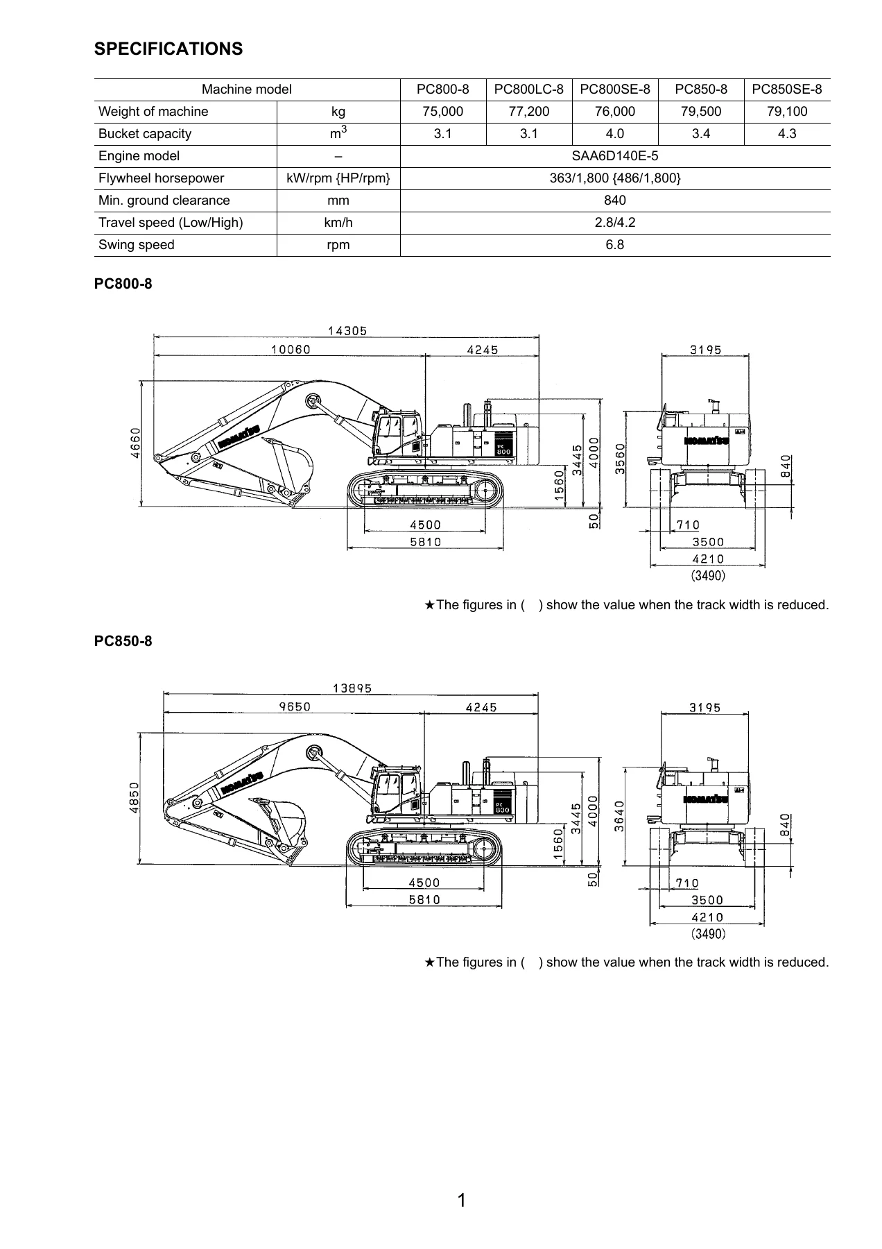
Complete field assembly instruction manual for Komatsu PC800-8, PC800LC-8, PC800SE-8, PC850-8 and PC850SE-8 hydraulic excavators. Covers chassis assembly, backhoe and loading shovel work equipment, counterweight remover, and post-assembly inspection. Document GEN00048-05.
Description
Komatsu PC800-8, PC850-8 Hydraulic Excavator Field Assembly Instruction Manual – GEN00048-05
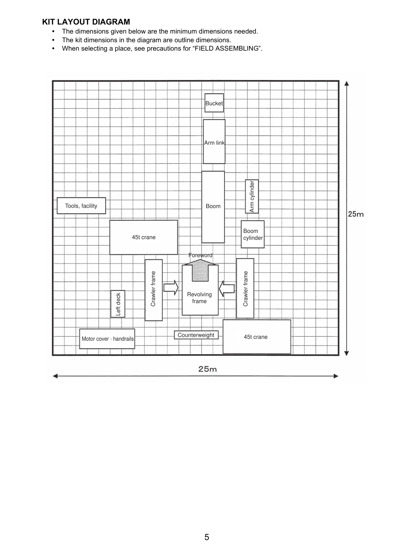
When a Komatsu PC800-8 or PC850-8 arrives on site in its transport configuration, this GEN00048-05 Field Assembly Instruction manual is the document that gets it back together. It covers the complete reassembly sequence for the PC800-8, PC800LC-8, PC800SE-8, PC850-8 and PC850SE-8 hydraulic excavators – from bolting the track frames back onto the revolving frame through to flushing the hydraulic circuit and filling in the final assembly inspection report. Every procedure is written for the field mechanic working with a crane, a torque wrench and a grease gun, not for a workshop with a full parts counter behind it.
File Details
- Manual type: Field Assembly Instruction
- Brand: Komatsu
- Models covered: PC800-8, PC800LC-8, PC800SE-8, PC850-8, PC850SE-8
- Serial numbers: PC800-50001, PC800LC-50001, PC800SE-50001 and up, PC850-10001, PC850SE-10001
- Language: English
- Page count: 181 pages
- File format: PDF
- Document number: GEN00048-05
Chapters Covered
- A. Assembly of Chassis
- B. Assembling of Work Equipment of Backhoe
- C. Assembling of Work Equipment of Loading Shovel
- D. Assembling of Counterweight Remover
- M. Procedure for Inspection and Maintenance after Completion of Assembly
A. Assembly of Chassis
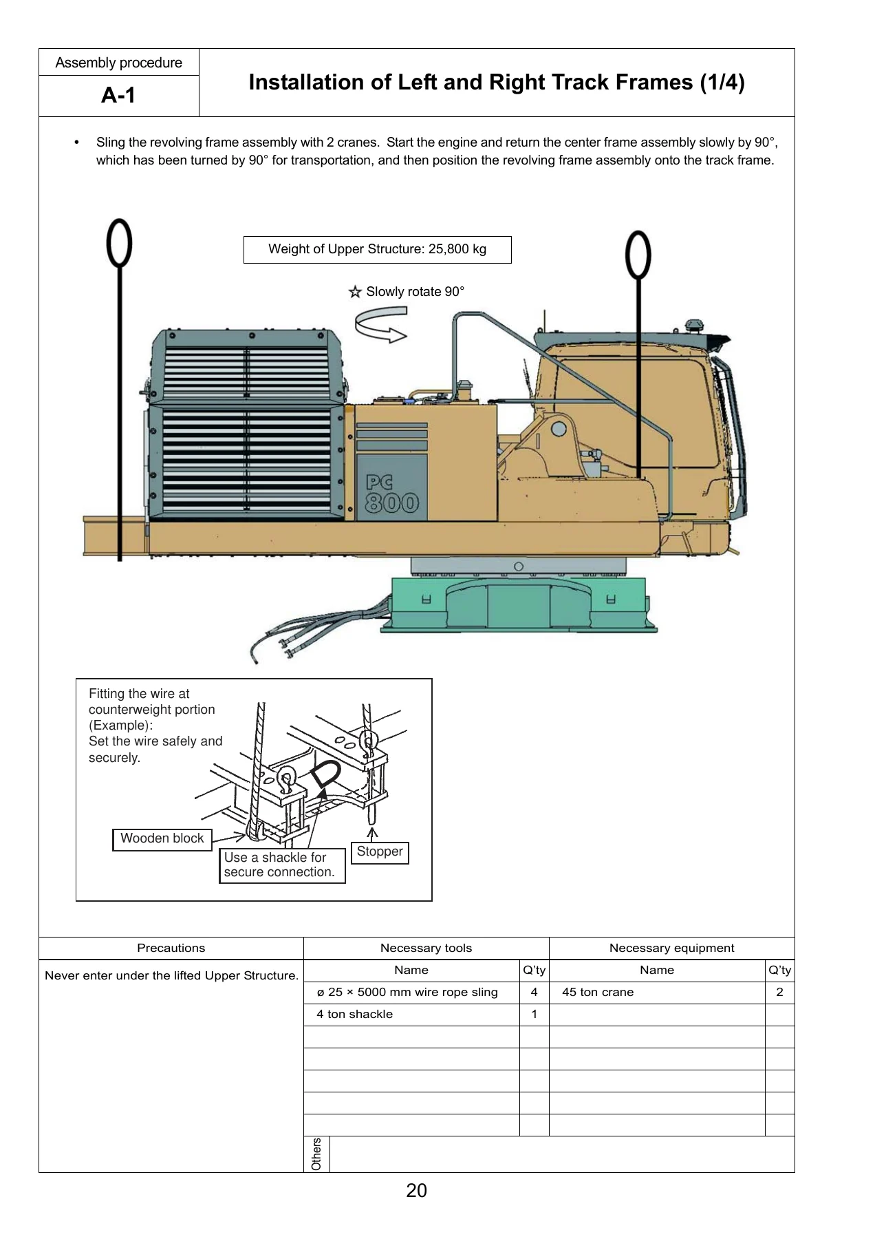
This is where the machine starts coming back together. The chapter opens with the installation of the left and right track frames onto the center frame, including the use of hydraulic jacks and wooden blocks to raise the track for bolt tightening access. It then walks through the travel pipe installation, top guard, radiator cover, rearview mirror and left side step. Handrail installation is covered both with and without the top guard. The muffler tail tube, counterweight sheet, counterweight itself and the KOMTRAX antenna (where equipped) all get their own procedures. The chapter closes with the step light, air bleeding of the travel motor, installation of the travel piping cover, testing and adjusting track shoe tension, and a full check of fuel, coolant and oil levels before the machine is started. A final section lists the parts that need touching up after field assembly, including the underside of the boom, arm, counterweight and bucket.
B. Assembling of Work Equipment of Backhoe
This chapter covers the backhoe configuration from the arm cylinder outwards. It begins with assembly of the arm cylinder and connection of the arm cylinder hoses, then moves to the boom cylinder foot, relieving residual pressure from the hydraulic circuit, and installation of the boom cylinder hoses. The boom foot dust seal gets its own page, followed by assembly of the complete boom, hose connections for the arm and bucket circuits, and the quick return hose. Boom cylinder installation comes next, then the arm assembly, the hose between boom and bucket cylinder, and the bucket assembly itself. Lubrication piping, wiring of the work equipment, greasing after assembly, and air bleeding from the hydraulic cylinders round out the chapter. Every pin, shim and torque value is called out where needed.
C. Assembling of Work Equipment of Loading Shovel
The loading shovel configuration gets its own full assembly sequence. It starts with releasing residual pressure in the hydraulic circuit and pulling the boom foot pin and boom cylinder foot pin. From there, the boom and arm assembly is installed, followed by the flushing piping between chassis and boom, for the boom and arm cylinders, for the bucket cylinder, and for the bottom dump cylinder. Boom cylinder installation and its foot, hoses and rod pin are covered in detail. Arm cylinder hoses, bucket cylinder and its hose, connecting hoses between chassis and boom top, and bottom dump cylinder hoses all have dedicated procedures. The bucket assembly, working lamps, work equipment grease piping, greasing after assembly, and bleeding air from the work equipment circuit complete the section.
D. Assembling of Counterweight Remover
This chapter covers the counterweight remover attachment. It starts with installation of the rubber cushions and adjustment of the shims for the counterweight, then moves through greasing, installation of the counterweight remover itself, covers, and hoses. Bleeding air from the counterweight remover circuit is covered, followed by installation of the counterweight, accessories, and a final check of operation. The shim adjustment procedure includes measuring distances and selecting the right combination of 1.0 mm, 1.5 mm, 0.5 mm and 3.2 mm shims to get the clearance right.
M. Procedure for Inspection and Maintenance after Completion of Assembly
Once the machine is assembled, this chapter tells you how to bring it back to life. It covers inspection of the oil level in the hydraulic tank and refill, replacement of the return filter (standard filter to flushing filter), flushing of the hydraulic circuit, and replacement of the return filter again (flushing filter to standard filter). The error code section explains how to use the monitor panel to check for abnormality records in both the electrical and mechanical systems, and how to reset the electrical system record. A field assembly inspection report for both the backhoe and loading shovel configurations is included at the end of the manual.
What This Manual Does For You
Field assembly of a PC800-8 or PC850-8 is not a job you want to improvise. The work equipment is extremely heavy, the hydraulic pressures are high, and the procedures involve lifting and positioning components weighing several tonnes with a crane while the engine is running. This manual gives you the correct sequence for every step, the torque values for every critical bolt, the shim sizes needed for pin clearance, the air bleeding procedure for each hydraulic circuit, and the inspection criteria to confirm the machine is ready to work. It also includes the field assembly inspection report so you can document that the job was done to specification.
If you are reassembling a PC800-8 or PC850-8 that was delivered in its transport configuration, this is the document that tells you what to do first, what to check before you tighten anything, and how to confirm the machine is safe to operate. It covers both the backhoe and loading shovel work equipment, and the counterweight remover attachment.
Delivery
IMAGES PREVIEW
This Komatsu PC800-8 PC850-8 Field Assembly Instruction manual is delivered as an instant PDF download. No shipping, no waiting. The file works on any device – laptop, tablet or phone – and can be printed if you need a paper copy in the field. The PDF is ready to download immediately after payment.



Reviews
There are no reviews yet.