
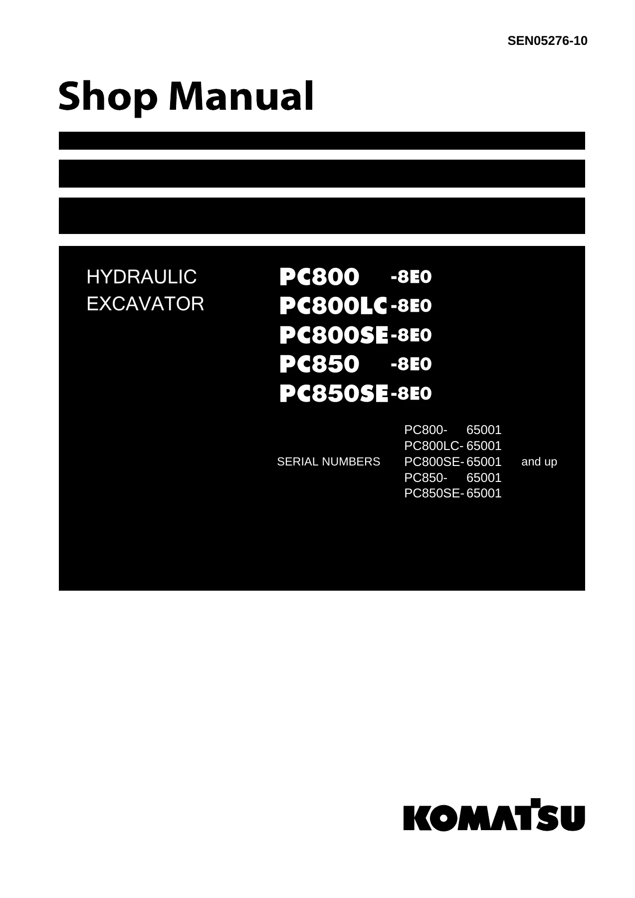
Komatsu PC800-8E0 PC800LC-8E0 PC800SE-8E0 PC850-8E0 PC850SE-8E0 Hydraulic Excavator Shop Manual – SEN05276-10 PDF Download
Original price was: $67.95.$44.95Current price is: $44.95.
Complete Komatsu Shop Manual for PC800-8E0, PC800LC-8E0, PC800SE-8E0, PC850-8E0 and PC850SE-8E0 hydraulic excavators. Covers specifications, structure and function, testing and adjusting, troubleshooting, disassembly and assembly, maintenance standards, air conditioner and complete hydraulic and electrical circuit diagrams. Document SEN05276-10.
Description
Komatsu PC800-8E0, PC800LC-8E0, PC800SE-8E0, PC850-8E0 and PC850SE-8E0 Hydraulic Excavator Shop Manual
This is the complete Komatsu Shop Manual covering the PC800-8E0, PC800LC-8E0, PC800SE-8E0, PC850-8E0 and PC850SE-8E0 hydraulic excavators, serial numbers 65001 and up. Published under document number SEN05276-10, this is the same comprehensive workshop reference used by professional technicians for everything from routine specification checks to complete component overhauls. Every section is organised exactly as Komatsu structured it, so you can move from a system description straight into the relevant testing, troubleshooting or disassembly procedure without hunting through unrelated material.
File Details
- Manual Type: Shop Manual (Chassis Volume)
- Brand: Komatsu
- Models Covered: PC800-8E0, PC800LC-8E0, PC800SE-8E0, PC850-8E0, PC850SE-8E0
- Serial Numbers: 65001 and up
- Document Number: SEN05276-10
- Language: English
- File Format: PDF
- Page Count: 1352 pages
Chapters Covered
- 00 Index and foreword
- 01 Specification
- 10 Structure and function
- 20 Standard value table
- 30 Testing and adjusting
- 40 Troubleshooting
- 50 Disassembly and assembly
- 60 Maintenance standard
- 80 Appendix
- 90 Diagrams and drawings
01 Specification
The specification chapter gives you the full technical baseline for every covered model. It includes specification drawings, complete dimensional and performance specifications, a table of weights for major components, and the table of fuel, coolant and lubricants with ambient temperature ranges and recommended Komatsu fluids. This is where you confirm capacities and operating limits before starting any job.
10 Structure and function
This chapter explains how the machine is built and how each system works. It covers the engine and cooling system, coupling and coupling lubrication, power train including swing circle, swing machinery and final drive, undercarriage and frame including track frame and idler cushion, and the complete hydraulic system from component layout and hydraulic tank through the main pump, pump control system, servo valve, self-pressure reducing valve, cooling fan pump and motor, control valve, straight-travel valve, swing motor, travel motor, PPC valve, solenoid valve, accumulator and filters. The electrical system section covers engine control, electric control system, monitor system, sensors and the KOMTRAX system. Read this before troubleshooting so you understand what each component is supposed to do.
20 Standard value table
Contains the standard value tables for engine and machine. Use these tables during testing and adjusting to judge whether a measurement is within specification or has reached a repair limit. Engine values cover speed, boost pressure, exhaust temperature, exhaust gas colour, valve clearance, compression pressure, blowby pressure, engine oil pressure, EGR valve and bypass valve drive pressure, and belt tensions. Machine values cover control valve spool travel, control lever travel and play, operating effort, relief pressures for boom, arm, bucket, swing and travel circuits, pump EPC solenoid output pressure, jet sensor differential pressure, PPC valve output pressure, electronic control system values, swing performance, travel performance, work equipment hydraulic drift, work equipment speed, time lag, internal oil leakage, hydraulic pump delivery, and fan speed and circuit pressures.
30 Testing and adjusting
This is the measurement and adjustment chapter. It lists the tools required for testing, adjusting and troubleshooting, then walks through engine and cooling system tests including engine speed, intake air pressure, exhaust gas temperature, exhaust gas colour, valve clearance, compression pressure, blowby pressure, engine oil pressure, EGR valve and bypass valve drive pressure, fuel system pressure and return rate, fuel circuit bleeding and leakage testing, and alternator and air conditioner compressor belt tension. Undercarriage and frame coverage includes swing circle bearing clearance and track tension. Hydraulic system coverage includes work equipment, swing and travel circuit oil pressures, control circuit oil pressure, main pump control signal, PPC valve output pressure, solenoid valve and swing PPC shuttle valve and swing priority selector valve outlet pressures, PPC valve play adjustment, travel deviation, hydraulic drift inspection, fan speed and circuit oil pressure, fan pump EPC current and solenoid valve outlet pressure, oil leakage measurement, releasing remaining pressure and bleeding air. Electrical system coverage includes special functions of the machine monitor, handling the engine controller voltage circuit, and preparatory work for electrical troubleshooting.
40 Troubleshooting
A large, structured troubleshooting reference. It opens with general troubleshooting information, checks before troubleshooting, classification and procedures, a failure codes table, symptom and troubleshooting numbers, and an explanation of how to read the troubleshooting tables. Troubleshooting by failure code covers engine controller lock cautions, air cleaner clogging, charge voltage low, engine oil pressure low, engine oil level low, engine water overheat, engine water level low, hydraulic oil overheat, and a full range of engine controller codes covering ECM internal failure, Ne and Bkup speed sensor errors, charge air pressure sensor high and low errors, throttle sensor errors, engine oil pressure sensor errors, coolant temperature sensor errors, charge air temperature sensor errors, sensor supply voltage errors, ambient pressure sensor errors, engine overspeed, Ne speed sensor supply voltage, fuel temperature sensor errors, IMV/PCV1 and PCV2 errors, injector open and short errors, calibration code incompatibility, injector drive circuit error, battery voltage errors, rail pressure errors, supply pump pressure low error, Ne speed sensor error, Bkup speed sensor phase error, continuous data lost error, Bkup speed sensor error, EGR valve servo errors, BP valve solenoid current errors, bypass valve servo errors, BP valve position sensor errors, KOMNET datalink timeout, throttle sensor supply voltage errors, rail pressure very low, EGR valve position sensor errors, EGR valve solenoid current errors, and grid heater relay errors. Machine monitor codes cover battery relay drive, flash light relay, step light relay, personal code relay, GPS antenna, pump solenoid power, 5V sensor power, model selection, CAN disconnection, auto lubrication, camera power supply, GPS module, ambient temperature sensor, hydraulic oil sensor, jet sensor open and short circuits, pump pressure sensor open and short circuits, travel alarm, swing priority solenoid, travel speed solenoid, swing brake solenoid, fan reverse solenoid, bottom dump priority solenoid, travel junction solenoid, 2-stage relief solenoid, fan pump EPC solenoid, and front and rear pump EPC solenoid open and short circuits, plus wiper and washer drive faults. Electrical system troubleshooting in E-mode covers engine does not start, preheater, machine monitor display, basic check monitor, precaution and emergency stop items, coolant temperature gauge, fuel gauge, hydraulic oil temperature gauge, display differences, function switch, automatic warm-up, auto-decelerator, working mode, travel speed, alarm buzzer, service meter, service mode, work equipment and swing and travel operation, machine push-up, boom shockless, swing brake, windshield wiper and washer, travel alarm, monitoring function indicators, electric grease gun, KOMTRAX, horn and step light. Hydraulic and mechanical system troubleshooting in H-mode covers slow or weak work equipment, swing and travel, engine speed drop or stall, no operation, unusual noise from hydraulic pump, boom, arm and bucket speed and power, no movement, large hydraulic drift, large time lag, heavy lift function, machine push-up function, boom shockless function, travel deviation, travel speed, swing operation, swing speed, swing overrun, swing shock, swing noise and swing drift. Engine troubleshooting in S-mode covers startability, engine does not start, engine does not pick up smoothly, engine stops during operation, rough or unstable running, lack of power, black exhaust smoke, oil consumption, oil contamination, fuel consumption, oil in coolant, oil pressure drop, oil level rise, overheating, unusual noise and vibration.
50 Disassembly and assembly
This chapter explains how to remove, install, disassemble and assemble every major component. It starts with general information, coating materials, special tools and sketches of special tools, then works through engine and cooling system including removal and installation of the engine, PTO and hydraulic pump assembly, cooling assembly, aftercooler, fuel cooler and air condenser, fan motor and fuel tank, engine fuel supply pump, cylinder head, fuel injector, engine front seal and engine rear seal. Power train coverage includes PTO, swing motor and swing machinery, swing circle and final drive. Undercarriage and frame coverage includes track shoe separation and connection, one-link field disassembly and assembly, idler, idler adjustment cylinder, recoil spring, carrier roller, track roller, revolving frame and counterweight. Hydraulic system coverage includes hydraulic tank, main pump, main pump input shaft oil seal, cooling fan pump, control valve, swing motor, center swivel joint, travel motor, solenoid valve, boom damping valve, work equipment PPC valve, travel PPC valve, hydraulic cylinder and grease gun. Work equipment coverage includes bucket cylinder, arm cylinder, boom cylinder, bottom dump cylinder, bucket, arm, boom and complete work equipment assembly. Cab and attachments coverage includes operator’s cab, cab glass, front window and work equipment control lever. Electrical system coverage includes air conditioner unit, engine controller, monitor, pump controller and KOMTRAX terminal.
60 Maintenance standard
Gives maintenance standard values for each component with criteria and remedies for disassembly and service. Coverage includes coupling, swing circle, swing machinery, final drive, sprocket, track frame and idler cushion, idler, carrier roller, track roller, track shoe, cooling fan motor, control valve, swing motor, center swivel joint, PPC valve, work equipment, work equipment dimensions and hydraulic cylinder.
80 Appendix
The appendix covers the air conditioner system. It includes precautions for refrigerant, air conditioner components, configuration and function of the refrigeration cycle, outline of the refrigeration cycle, air conditioner unit, air conditioner controller, compressor, condenser, receiver drier, procedure for testing and troubleshooting, circuit diagram and arrangement of connector pins, system diagram, detail of the air conditioner unit, parts and connectors layout, testing air leakage, testing with self-diagnosis function, testing temperature control, testing vent changeover, testing FRESH/RECIRC air changeover, testing inner sensor, testing evaporator temperature sensor, testing sunlight sensor, testing the dual pressure switch for refrigerant, testing relays, troubleshooting charts, troubleshooting for power supply and CAN communication, compressor and refrigerant system, blower motor system, temperature control, vent changeover, FRESH/RECIRC changeover, temperature sensor system, troubleshooting with gauge pressure, connection of service tool, precautions for disconnecting and connecting air conditioner piping, and handling of compressor oil.
90 Diagrams and drawings
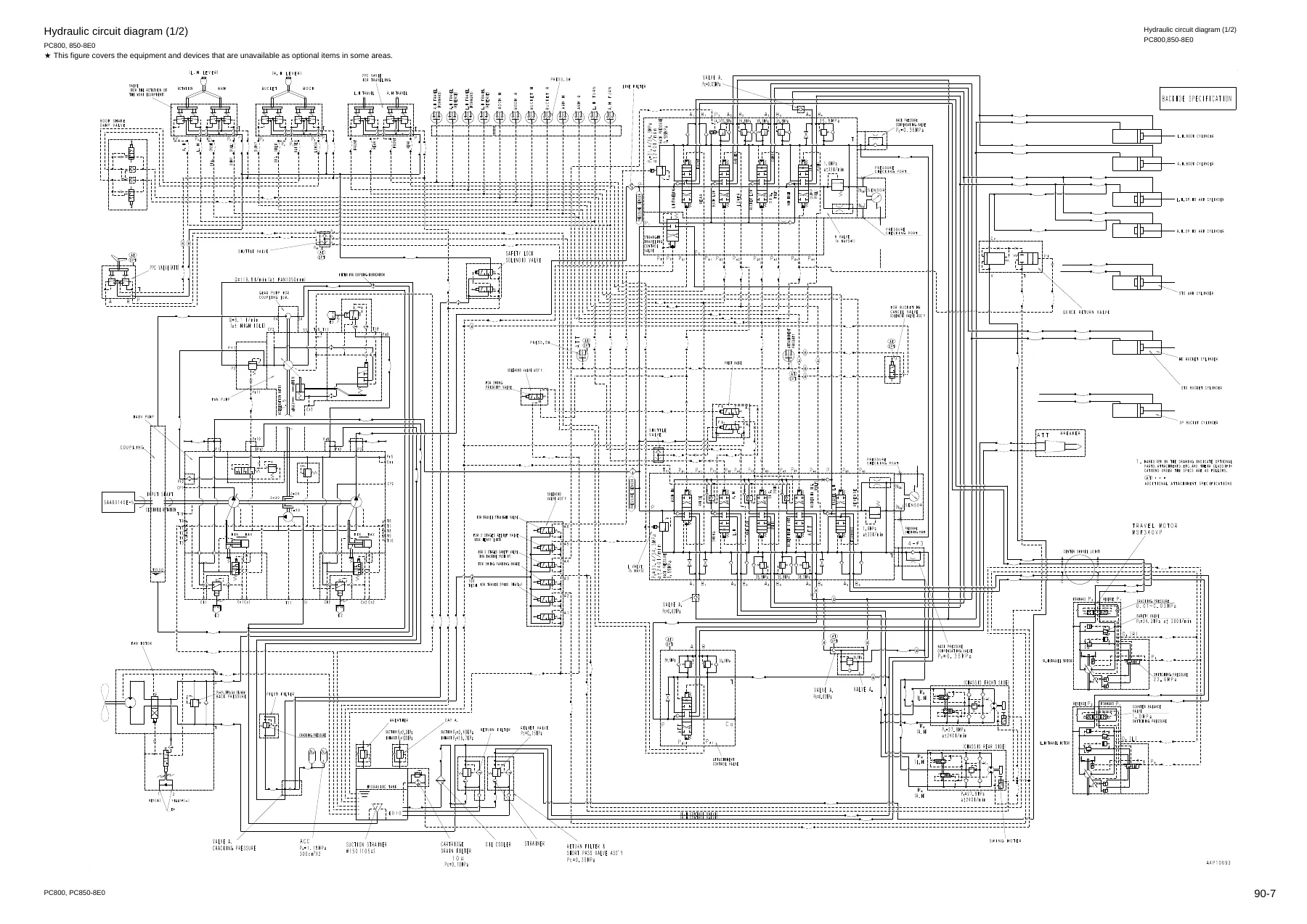
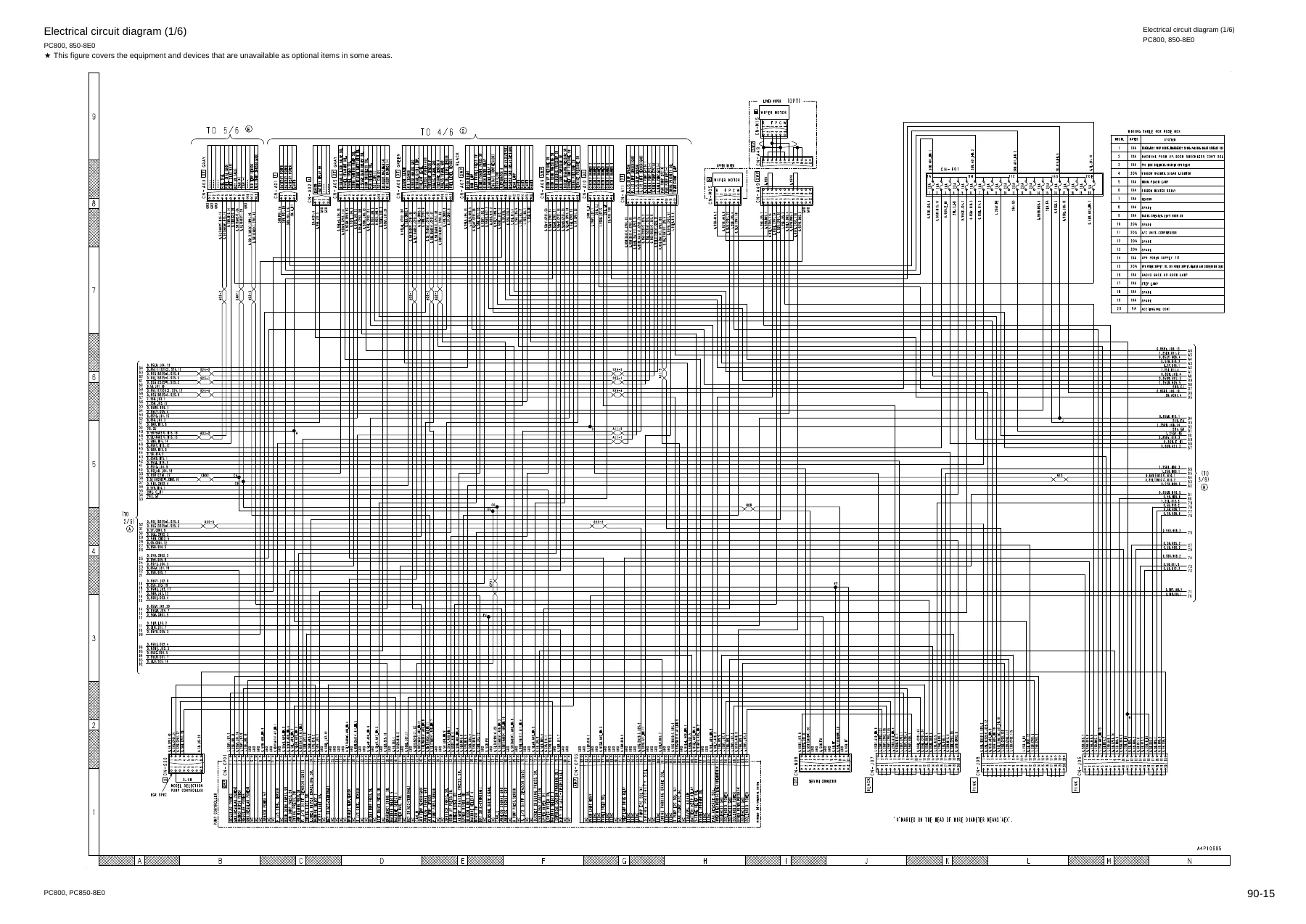
Contains the hydraulic circuit diagram with symbols used in hydraulic circuit diagrams, and the electrical circuit diagram with symbols used in electric circuit diagrams. These are the full system diagrams you need when tracing a fault through the hydraulic or electrical circuit.
What You Can Do With This Komatsu Shop Manual
With the PC800-8E0, PC800LC-8E0, PC800SE-8E0, PC850-8E0 and PC850SE-8E0 Shop Manual in hand you can carry out engine diagnostics, hydraulic system testing and adjustment, electrical troubleshooting, undercarriage inspection, swing and travel system repair, work equipment cylinder and linkage service, and complete component removal and installation. The testing and adjusting chapter gives you the exact pressures, speeds, clearances and torques to verify, and the standard value table tells you whether a reading is acceptable or has reached a repair limit. The troubleshooting chapters are organised by failure code, by symptom and by system so you can move from a complaint to the correct diagnostic path without guesswork. The disassembly and assembly chapter gives you the special tools, coating materials, tightening torques and step-by-step procedures for pulling and rebuilding major assemblies, and the maintenance standard chapter gives you the wear limits and remedies for every component group.
Why Correct Procedures and Specifications Matter
Large hydraulic excavators like the PC800-8E0 and PC850-8E0 run high hydraulic pressures, precise electronic control systems and heavy structural loads. Working from the wrong specification or skipping a required adjustment can cause repeat failures, damaged components or unsafe machine condition. This manual gives you Komatsu’s own standard values, adjustment procedures and disassembly sequences so the repair is done correctly the first time. The hydraulic circuit diagram and electrical circuit diagram let you trace circuits logically instead of replacing parts on suspicion, and the troubleshooting tables are built around the failure codes the machine itself reports, so you can go straight to the likely cause.
IMAGES PREVIEW
Instant PDF Delivery
The manual is delivered as an instant PDF download. No shipping, no waiting, no physical book to lose. Once you complete checkout you can open the file on a workshop computer, laptop, tablet or smartphone, print the pages you need for the job, and keep the complete manual on hand for every future service. Whether you are a Komatsu owner-operator, a fleet maintenance manager or an independent heavy equipment technician, this SEN05276-10 Shop Manual gives you the full factory-level reference for the PC800-8E0, PC800LC-8E0, PC800SE-8E0, PC850-8E0 and PC850SE-8E0 hydraulic excavators in one complete, printable document.

Reviews
There are no reviews yet.