
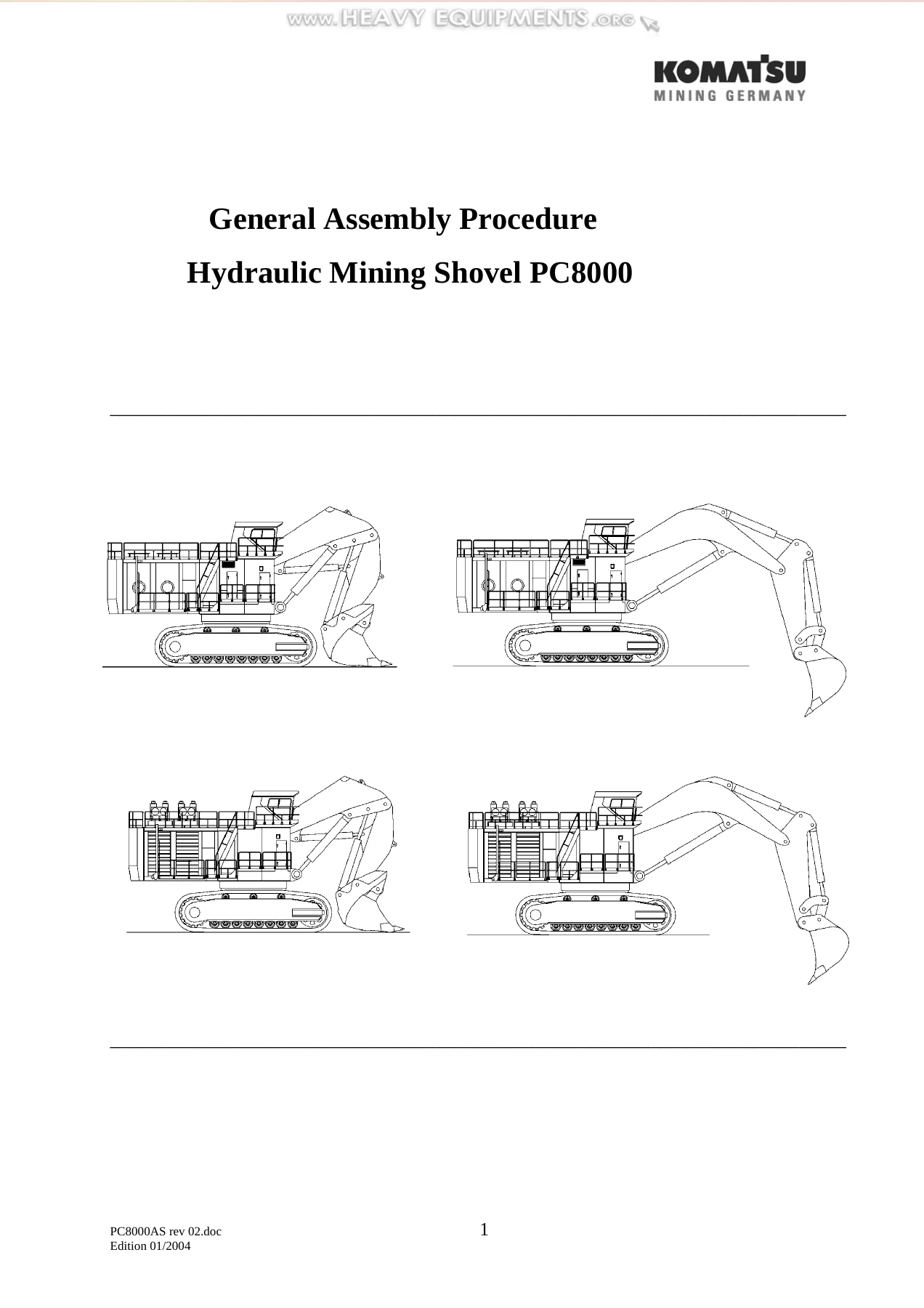

Komatsu PC8000 Hydraulic Mining Shovel General Assembly Procedure Manual 2004 – PDF Workshop Guide
Original price was: $67.95.$44.95Current price is: $44.95.
Complete General Assembly Procedure for the Komatsu PC8000 hydraulic mining shovel, Edition 01/2004. Covers undercarriage build-up, superstructure mounting, boom and stick assembly, drive unit installation, hydraulic and electrical connections, fire suppression system setup, and pre-commissioning checks.
Description
Komatsu PC8000 General Assembly Procedure – Edition 01/2004
This is the complete General Assembly Procedure for the Komatsu PC8000 hydraulic mining shovel, published in Edition 01/2004 under document number PC8000AS rev 02.doc. The manual guides skilled assembly personnel through every stage of building the excavator from its delivered components, from crawler segment mounting to final commissioning checks. It applies to both diesel-driven and electric-driven configurations and covers the front shovel attachment, backhoe attachment, and Bullclam bucket variants.
File Details
- Manual Type: General Assembly Procedure
- Brand: Komatsu
- Model: PC8000 Hydraulic Mining Shovel
- Language: English
- Page Count: 156
- File Format: PDF
- Document Number: PC8000AS rev 02.doc
- Edition: 01/2004
Chapters Covered
- Mounting of Crawler Segments to the Side Frame
- Assembly of Undercarriage
- Assembly of Cable Reel Unit
- Mounting of Final Drives / Closing the Chains
- Mounting of Auxiliary Weight at the Undercarriage
- Mounting of Slew Ring underneath the Superstructure Platform
- Assembly of Superstructure Platform onto the Undercarriage
- Assembly of the Prime Drive Unit to the Superstructure Platform
- Preassembly Boom- and Stick Cylinders to the Boom
- Mounting of Boom
- Mounting of Counterweight
- Mounting of Fuel Tank or Main Switch Cabinet
- Mounting of Cab Support
- Mounting of Operators Cab
- Mounting of Hydraulic Oil Tank
- Mounting of Hydraulic Oil Coolers
- Mounting Handrails, Cat Walks, Steps, Stairs and Ladders
- Mounting of Hydraulic Access Ladder
- Installation of Muffler and Cover
- Installation of Air Filters
- Installation of Auxiliary Crane, Generator Set and Lubrication Stations
- Connection of Cable Harnesses to the X-Boards
- Installation of Hose Connections on Hydraulic Tank and Coolers
- Installation of HP Hoses between HP Filters and Main Valve Blocks
- Mounting of Bucket Cylinders to the Boom
- Mounting of Stick
- Installation of Hose Connections to the Boom
- Filling Up Hydraulic Tank
- Filling Up Fuel Tank
- Pre-Checks Prior First Engine Start
- Mounting of Stick Cylinders to the Stick
- Mounting of the Pin Seals
- Assembly of Bullclam Bucket to the Stick
- Assembling and Testing the Fire Detection, Actuation and Suppression System
- Checks and Adjustments Prior Commissioning
Undercarriage and Crawler Assembly
This section walks through mounting the crawler segments to the side frames, assembling the undercarriage with the center carbody, installing the cable reel unit, and mounting the final drives. It includes detailed instructions for opening the disk brake with a hand pump (25–35 bar), aligning splines, inserting the drive shaft, and closing the chains over the sprocket and idler wheel. Torque values for the undercarriage pins, retainer plates, and slewing ring bolts are provided.
Slew Ring and Superstructure Platform
Covers mounting the slew ring underneath the superstructure platform, including the special procedure for determining the tightening torque using the test block, cleaning contact surfaces to be grease-free, and using guide pins for alignment. The assembly of the superstructure platform onto the undercarriage is detailed with bolt tightening sequences, rotary distributor port identification (A–D, F, L, ST, K1/K2), and the electric drive high-voltage cable introduction.
Prime Drive Unit Installation
This chapter covers both diesel and electric drive configurations. For electric drive, it explains checking motor rotation direction (counter-clockwise viewed from the PTO gear) before mounting the coupling, with torque values for the flexible coupling nuts. The overview section identifies all major drive unit components including the coolant expansion tank, radiator, fuel cooler, hydraulic motor for radiator fan drive, engine air cleaner, turbocharger, aftercooler, ECMs, starter motors, main hydraulic pumps, and suction oil reservoir.
Boom, Stick and Attachment Assembly
Detailed procedures for preassembling boom and stick cylinders to the boom, mounting the boom to the superstructure, installing the counterweight, and assembling the stick. It covers both the front shovel and backhoe attachment variants, including the Bullclam bucket assembly with its two-part delivery (clam and rear wall). Pin seal mounting procedures for both inner and outer bushing seals are included, with exploded diagrams showing seal ring, fixing half, bolt, bushing, pin, and cylinder eye. Torque values for the M48 counterweight bolts (7500 Nm) and other critical fasteners are listed.
Hydraulic, Electrical and Auxiliary Systems
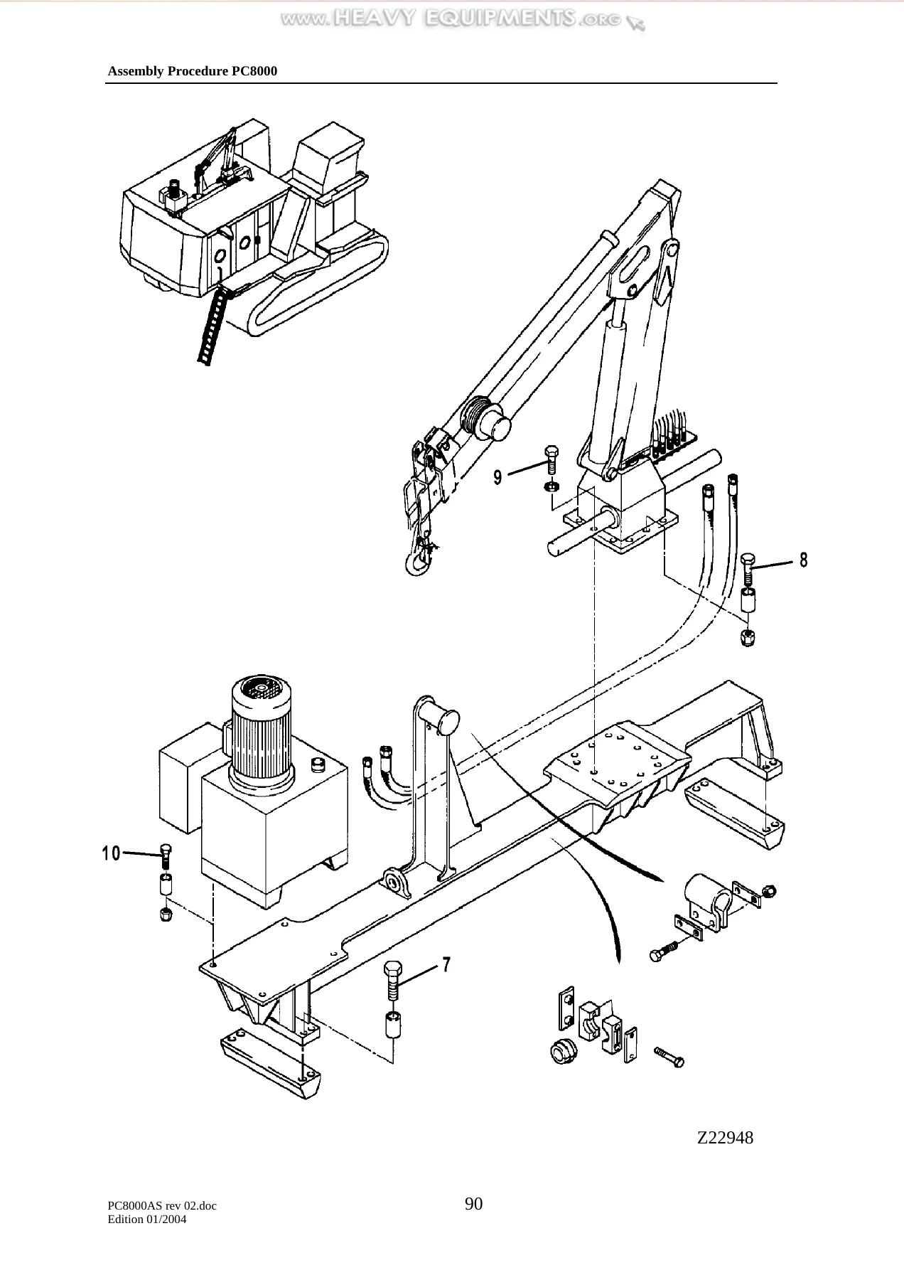
Includes mounting the hydraulic oil tank, hydraulic oil coolers, fuel tank or main switch cabinet, cab support, operator’s cab, air filters, muffler assembly, auxiliary crane, generator set, and lubrication stations. The cable harness connection chapter covers routing to junction boards X2 and X3, plug connections below the cab support, battery cables, medium voltage and high voltage cabinet connections, and slip ring wiring. Hose connection procedures for the hydraulic tank, coolers, HP filters, main valve blocks, boom, and auxiliary hydraulic oil cooler are all detailed.
Fluids, Pre-Checks and Commissioning
Filling procedures for the hydraulic tank and fuel tank, including filling via the service arm or direct refilling plug, air bleeding from pump suction ports, checking oil levels in main pump housings, and using the correct hydraulic oil per the Maintenance Manual. Pre-checks for initial start-up cover fluid levels, fuel line bleeding, pump suction bleeding, crawler tensioning valve positions (118.1 OPEN, 118.2 OPEN, 118.3 OPEN, 118.4 CLOSED), swing parking brake activation, and engine start-up at low idle for 5 minutes. Final checks include testing the hydraulic access ladder, service arm movement, EBL (Electronic Bucket Limiting), ECS system, battery charging unit, and main motor protection relay.
Safety Systems and Fire Suppression
The manual includes complete assembly and testing procedures for two fire systems: the Checkfire MP-N electric detection and actuation system controlling the Carbon Dioxide suppression system for the slip ring unit, high voltage switch cabinet, and medium/low voltage switch cabinets; and the Checkfire SC-N electric detection and warning system monitoring the machinery house via a linear detection wire. Wiring diagrams, connection tables, and step-by-step testing procedures are provided.
Why This Assembly Procedure Manual Matters
Assembling a Komatsu PC8000 is not a task for guesswork. With components weighing up to 46,000 kg (gross) and torque values reaching 7,500 Nm, every step must follow the correct sequence and specification. This manual provides the exact lifting points, pin part numbers, torque values, tightening sequences, and safety warnings required to build the machine correctly and avoid severe accidents or component damage.
The document includes a detailed packing list with weights, dimensions, and transport data; assembly site requirements (150 x 150 ft area, 150-ton mobile cranes, 25-ton small crane, forklift, chain pulls, shackles, ropes, hydraulic jacks, and a full tool list); a manpower and time schedule; and an illustrated component configuration plan for the erection site.
IMAGES PREVIEW
Your Instant Download
This Komatsu PC8000 General Assembly Procedure is delivered as an instant PDF download. No shipping, no waiting. Access it on any device — laptop, tablet, or smartphone — and print the pages you need for the assembly site. Whether you are a Komatsu service engineer, a mine maintenance planner, or a heavy equipment technician tasked with erecting this mining shovel, this manual gives you the complete, step-by-step procedure as published by Komatsu Mining Germany.
Reviews
There are no reviews yet.