
Komatsu PW200-7K PW220-7K Shop Manual – Full PDF Service & Repair Guide (K40001+)
Original price was: $49.95.$29.95Current price is: $29.95.
Complete Komatsu shop manual for the PW200-7K and PW220-7K wheeled excavators, serial K40001 and up, SAA6D102E-2 engine. 848 pages of specifications, structure and function, testing and adjusting, disassembly and assembly, plus hydraulic and electrical circuit diagrams.
Description
This Komatsu PW200-7K PW220-7K Shop Manual is the complete workshop reference for the PW200-7K and PW220-7K wheeled excavators, covering every machine from serial number K40001 upward and running the Komatsu SAA6D102E-2 diesel engine. At 848 pages it is the full service documentation for the model pair – not a condensed aftermarket summary – and it walks a technician through general specifications, structure and function theory, standard maintenance values, on-machine testing and adjusting, hydraulic and electrical diagnostics, and full disassembly and assembly of every major component.
File Details
- Manual type: Shop Manual (Service / Repair / Workshop)
- Brand: Komatsu
- Models covered: PW200-7K, PW220-7K (including the PW220-7 heavy duty option)
- Serial number coverage: K40001 and up
- Engine: SAA6D102E-2
- Language: English
- File format: PDF
- Page count: 848 pages
- Section numbers: 01 General, 10 Structure Function and Maintenance Standard, 20 Testing and Adjusting, 30 Disassembly and Assembly, 90 Others
- Reference number: UEBM001901
Chapters Covered
The manual is organised into five numbered chapters, each building on the previous one.
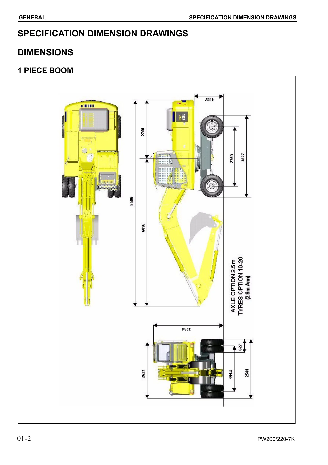
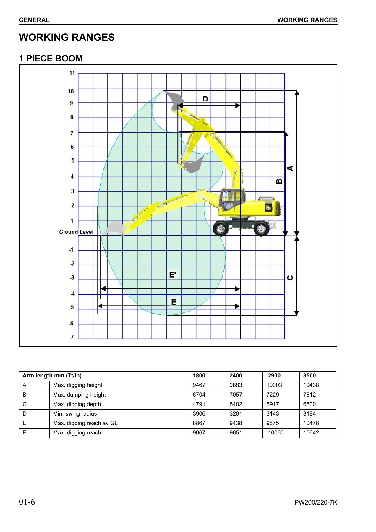
- 01 GENERAL – Specification dimension drawings (1 piece boom and 2 piece boom), working range charts for both boom configurations, full PW200-7 / PW220-7 specifications, weight table for handling and transport, and the fuel, coolant and lubricants chart with ambient-temperature oil grades and capacities.
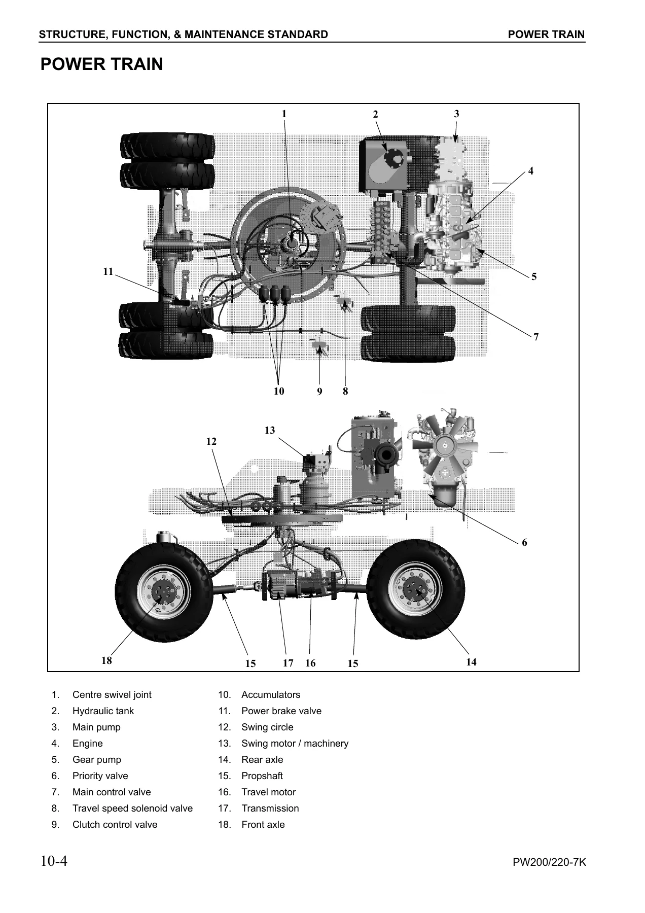
- 10 STRUCTURE, FUNCTION AND MAINTENANCE STANDARD – Engine related parts, radiator / oil cooler / charge air cooler, power train, swing circle, swing machinery, swing motor, undercarriage, transmission, travel motor, clutch control circuit, axle, suspension lock cylinder, braking system, brake/steer pump, priority valve, power brake valve, brake accumulator, steering train, steering column, orbitrol valve, hydraulic layout and circuit diagrams, hydraulic tank, hydraulic pump, pilot pressure control system, control valve, CLSS, centre swivel joint, travel PPC pedal, work equipment and swing PPC valve, service PPC pedal, solenoid valves, travel-boom-stabilizer solenoid valve, boom safety valve, hydraulic cylinders, outrigger and dozer cylinders, work equipment, air conditioner, electrical wiring diagram, engine control system, electronic control system, machine monitor system, overload warning device, sensors, attachment circuit hydraulic performance, travel system, steering system, and the service brake and suspension system.
- 20 TESTING AND ADJUSTING – Standard value tables for engine and chassis related parts, engine RPM inspection and adjustment, exhaust gas colour measurement, valve clearance, compression pressure, blow-by pressure, fuel injection timing, engine oil pressure, engine speed sensor adjustment, air compressor belt tension, emergency setting if failure occurs in the engine control system, swing circle bearing clearance, hydraulic oil pressure inspection for work equipment / swing / travel, control circuit oil pressure, pump PC and LS control circuit pressures, solenoid valve output pressures, PPC valve output pressures, PPC valve adjustment, travel motor relief pressure, hydraulic circuit pressure release, oil leakage measurement, air bleeding, diode inspection, the special function of the monitor panel, and the full troubleshooting sections for the electrical system (E-mode) and hydraulic and mechanical system (H-mode).
- 30 DISASSEMBLY AND ASSEMBLY – Removal and installation of governor motor, starting motor, fuel injection pump, engine front and rear seals, cylinder head, combination cooler, engine and hydraulic pump assembly, transmission and travel motor, swing motor and swing machinery, front and rear axles, propshaft, wheels, suspension lock cylinder, outrigger, dozer blade, swing circle, revolving frame, centre swivel joint, hydraulic tank, fuel tank, control valve, LS select valve, LS shuttle valve, pressure compensation valve, main relief valve, LS control EPC valve, EPC solenoid valve, PPC valve block, manifold block, oil seal in hydraulic pump input shaft, work equipment PPC valve, travel pedal valve, hydraulic cylinder assemblies, mono boom and 2 piece boom work equipment, air conditioner unit, counterweight, operator’s cab, monitor assembly, and governor pump controller.
- 90 OTHERS – Hydraulic circuit diagram (2 sheets) and electrical circuit diagram (3 sheets).
Read end to end, this is the whole lifecycle of the machine in one document. The General chapter alone gives a technician the boom geometry and working envelope, the oil and coolant chart by ambient temperature, and the weight of every removable assembly. The Structure and Function chapter then explains how each system is put together and why – the CLSS closed-centre load-sensing hydraulic system, the two-speed powershift transmission with its clutch control circuit, the suspension lock and axle oscillation arrangement, the swing holding brake, and the electronic monitor and engine control systems. The Testing and Adjusting chapter converts that theory into numbers: relief pressures, LS differential pressures, spool strokes, lever forces, drift limits, cylinder leakage amounts, travel speed and propshaft rpm windows, swing brake angle, and the full engine standard value table. The Disassembly and Assembly chapter then shows removal and installation sequences with tightening torques, special tool callouts, sealant and adhesive recommendations, and assembly tolerances for the transmission, axles, swing machinery, pumps and cylinders.
What You Can Do With This Manual
- Set, check and adjust every major hydraulic relief pressure – main relief, unload, swing safety, travel motor, boom safety, and the 2-stage relief function.
- Diagnose engine, hydraulic, mechanical and electrical faults using the E-mode and H-mode troubleshooting tables, Service Code and Failure Code listings, connector pin tables and wiring diagrams.
- Test the PC and LS pump control circuits, the LS-EPC, PC-EPC, and every solenoid valve on the 7-stage, 4-stage and 2-stage manifold blocks.
- Run oil leakage tests on cylinders, swing motor, travel motor and centre swivel joint against the manual’s pass/fail limits.
- Disassemble and reassemble the transmission, travel motor, swing motor and swing machinery, front axle, rear axle, hydraulic cylinders, and control valve – with torque values and special tools called out at each step.
- Read and use the monitor panel’s Operator’s Menu and Service Menu – monitoring, abnormality history, maintenance records, model selection, governor motor adjustment, pump absorption torque, low idle speed, and attachment flow rates.
- Handle the machine’s electrical system confidently with the full connector location chart, the connection table for pin numbers, and the three-sheet electrical circuit diagram.
Why This Level of Detail Matters
On a wheeled excavator, small deviations in hydraulic pressure, spool stroke or pump control current produce disproportionate symptoms – sluggish boom, slow travel, drifting swing, hunting engine, poor fine control, or unexpected stalling under load. The Komatsu PW200-7K PW220-7K troubleshooting section is written to narrow those symptoms down to a single test, and the standard value tables give the exact window a healthy machine should sit in. Every figure in this manual is presented in the units Komatsu prints – MPa and kg/cm2, litres per minute, rpm, millimetres, newtons, and degrees – so there is no conversion work before a reading is judged.
For the hydraulic system, the CLSS section explains the LS and PC valve relationship, the merge/divide function, the one-touch power max. function, the auto-deceleration logic, and the two-stage relief behaviour, so a technician is not just following a flowchart but understands what the pump is being told to do and why. On the mechanical side, the transmission and axle chapters walk through powershift clutch selection, brake application, bevel gear backlash setting, bearing preload and differential adjustment – the areas where measurement discipline matters most.
How You Receive It
IMAGES PREVIEW
This Komatsu PW200-7K PW220-7K shop manual is delivered instantly as a PDF download after payment. There is nothing to ship and nothing to wait for – the file lands in your account and can be opened on a workshop desktop, a laptop on the machine, a tablet in the cab, or a phone under the panel. Individual pages, chapters or the whole document can be printed for shop-floor use, and the PDF’s clean page numbering and structured contents make it easy to jump straight to the section you need. Whether you are setting up a machine for the first time, chasing an intermittent fault, planning a transmission overhaul, or just want the manufacturer’s numbers on hand before any repair, this is the document that gives you the answer without guesswork.

Reviews
There are no reviews yet.