
Komatsu WA150-5 Wheel Loader Shop Manual – SAA4D102E-2 Engine – Serial 65001-Up PDF
Original price was: $39.95.$23.95Current price is: $23.95.
Complete Komatsu WA150-5 Wheel Loader Shop Manual for serial 65001 and up. Covers SAA4D102E-2 engine, HST, transfer, axles, brakes, hydraulics, electrical, testing, troubleshooting, and disassembly. 753-page PDF.
Description
Komatsu WA150-5 Wheel Loader Shop Manual — Complete Service Reference for Serial 65001 and Up
The Komatsu WA150-5 Wheel Loader Shop Manual is the comprehensive service publication for machines from serial number 65001 and up, covering the SAA4D102E-2 diesel engine and every major system on the machine. This 753-page PDF provides technicians, workshop staff, and owners with the technical information needed for structure and function analysis, testing and adjustment, troubleshooting, disassembly, and assembly of the WA150-5 wheel loader. Every specification, procedure, and value is written specifically for this model and serial range.
File Details
- Manual Type: Shop Manual
- Brand: Komatsu
- Model: WA150-5 Wheel Loader
- Engine: SAA4D102E-2 Diesel Engine
- Serial Number: 65001 and up
- Language: English
- File Format: PDF
- Page Count: 753 pages
Chapters Covered
The manual is organised into the following chapters, each containing the necessary technical information for operations performed in a service workshop:
- 01 GENERAL — General Assembly Drawings, Specifications, Weight Table, List of Lubricant and Coolant
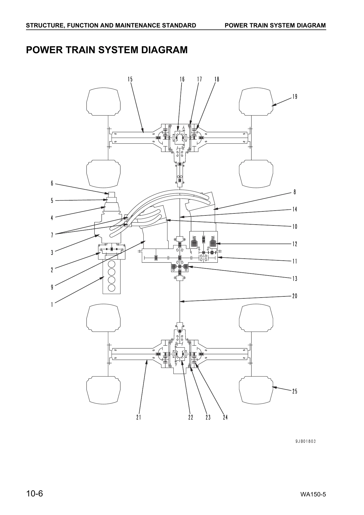
- 10 STRUCTURE, FUNCTION AND MAINTENANCE STANDARD — Engine Mount and Transfer Mount, Damper, Cooling System, Power Train, Power Train System Diagram, Drive Shaft (Propeller Shaft), HST Hydraulic Piping Diagram, HST Pump, High-Pressure Relief Valve, Low-Pressure Relief Valve, HST Charge Pump, Speed-Related Valve (DA Valve), High-Pressure Cut-Off Valve, HST Motor, EP Servo Valve, HA Servo Valve, Forward-Reverse Shuttle Valve, Transfer, Clutch Solenoid Valve, Axle, Differential, Limited-Slip Differential, Final Drive, Axle Mounting and Center Hinge Pin, Steering Piping, Steering Column, Priority Valve, Orbit-Roll Valve, Steering Cylinder, Emergency Steering Piping, Emergency Steering Valve, Brake Piping, Brake Valve, Inching Valve, Charge Valve, Accumulator (For Brake), Slack Adjuster, Brake, Parking Brake Control, Parking Brake, Hydraulic Piping, Work Equipment Lever Linkage, Hydraulic Tank, 3-Gear Pump Unit, Accumulator (For PPC Circuit), Lock Valve, E.C.S.S. Valve, Accumulator (For E.C.S.S.), Hydraulic Piping of Cooling System, Cooling Fan Motor, Work Equipment Control Valve, Work Equipment PPC Valve, Work Equipment Linkage, Bucket, Bucket Positioner and Boom Kick-Out, Work Equipment Cylinder, Air Conditioner, Machine Monitoring System, Machine Monitor, List of Items Displayed on Monitor, Electrical System (HST Controller System), HST Controller, Engine Start Circuit, Engine Stop Circuit, Preheating Circuit, Parking Brake Circuit, Electronically Controlled Suspension System, Sensors
- 20 TESTING AND ADJUSTING — Standard Value Table for Engine, Standard Value Table for Chassis, Tools for Testing Adjusting and Troubleshooting, Measuring Engine Speed, Measuring Exhaust Gas Color, Adjusting Valve Clearance, Measuring Compression Pressure, Measuring Blow-By Pressure, Testing and Adjusting Fuel Injection Timing, Measuring Engine Oil Pressure, Measuring and Testing Operating Force of Accelerator Pedal, Adjusting Engine Stop Solenoid, Adjusting Engine Speed Sensor, Testing and Adjusting Air Conditioner Compressor Belt Tension, Measuring Directional Lever, Testing and Adjusting HST Oil Pressure, Measuring Clutch Control Pressure, Testing and Adjusting Steering Wheel, Testing and Adjusting Steering Oil Pressure, Bleeding Air from Steering Circuit, Testing Hydraulic Fan, Measuring Brake Pedal, Testing and Adjusting Brake Pedal Linkage, Measuring Brake Performance, Testing and Adjusting Accumulator Charge Pressure, Measuring Brake Oil Pressure, Measuring Wear of Brake Disc, Bleeding Air from Brake Circuit, Measuring Parking Brake Performance, Testing and Adjusting Parking Brake Control Cable, Measuring and Adjusting Work Equipment Control Lever, Testing and Adjusting Work Equipment Hydraulic Pressure, Testing and Adjusting Work Equipment PPC Oil Pressure, Bleeding Air, Releasing Remaining Pressure in Hydraulic Circuit, Testing and Adjusting Bucket Positioner, Testing and Adjusting of Boom Kick-Out, Checking Proximity Switch Actuation Display Lamp, Procedure for Checking Diode, Method of Connecting T-Adapter for HST Controller, Special Functions of Machine Monitor (EMMS), Flow of Modes and Functions, Failure Code Table, PM Clinic Inspection Chart, plus Troubleshooting sections for HST Controller System (HST Mode), Travel Damper System (ECSS Mode), Monitor System (MON Mode), Electrical System (E Mode), Hydraulic and Mechanical System (H Mode), and Engine (S Mode)
- 30 DISASSEMBLY AND ASSEMBLY — Removal and Installation of Fuel Injection Pump Assembly, Nozzle Holder, Cylinder Head Assembly, Engine Assembly, Radiator Assembly, Air Aftercooler, Hydraulic Oil Cooler Assembly, Cooling Fan and Fan Motor Assembly, Fuel Tank Assembly, Transfer Assembly, Parking Brake Assembly, Front Axle Assembly, Rear Axle Assembly, Work Equipment Control Valve Assembly, Travel Damper Valve Assembly, Hydraulic Tank, Work Equipment Assembly, Operator’s Cab Assembly, Operator’s Cab Glass (Stuck Glass), Center Hinge Pin, Counterweight, Air Conditioner Unit Assembly, Air Conditioner Compressor Assembly, Monitor Panel, HST Controller Assembly; Disassembly and Assembly of Transfer Assembly, Parking Brake Assembly, Axle Housing Assembly, Differential Assembly, Hydraulic Cylinder Assembly
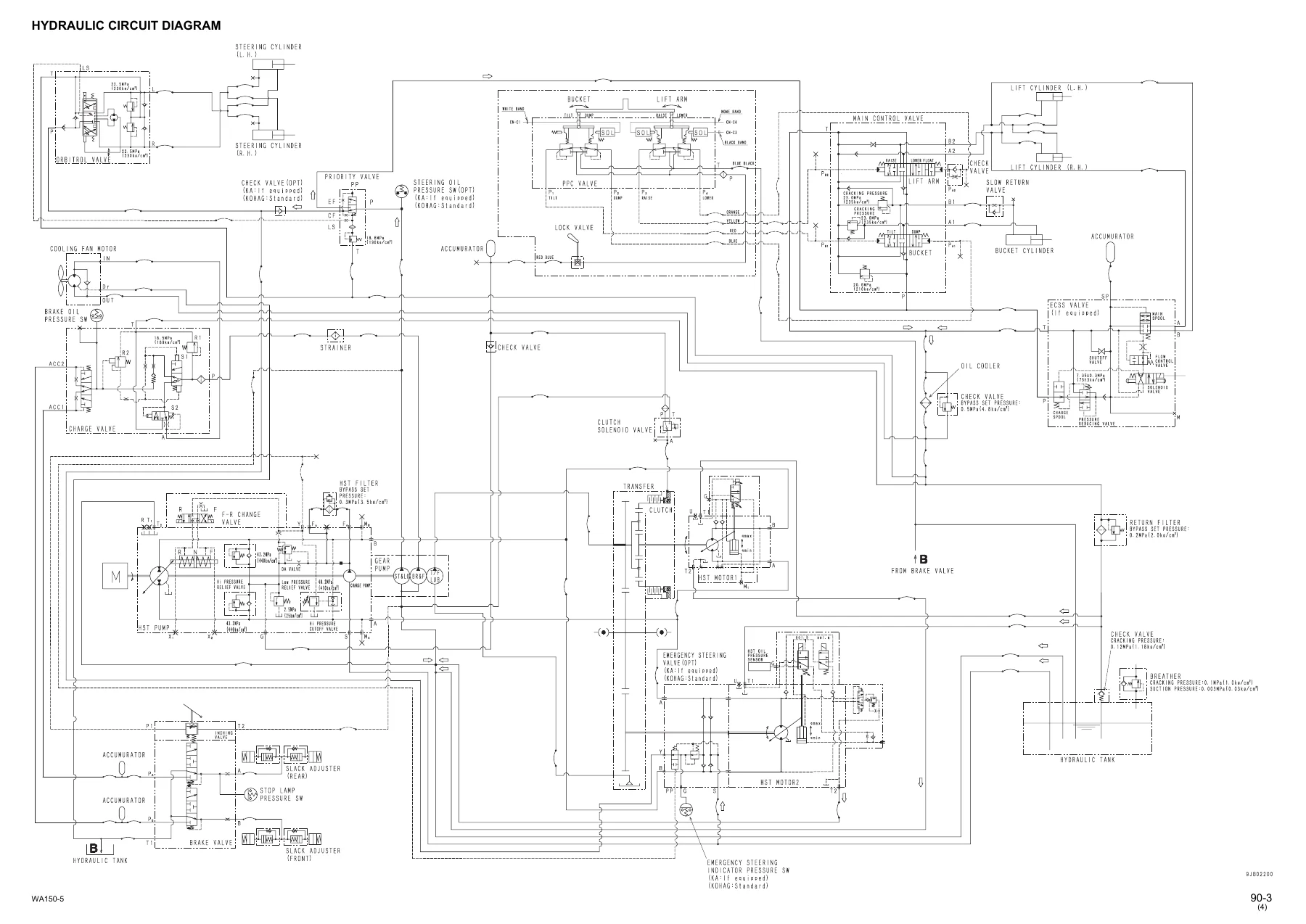
- 90 OTHERS — Hydraulic Circuit Diagram, Electrical Circuit Diagrams (ROPS Cab and ROPS Canopy)
What the Komatsu WA150-5 Shop Manual Provides
This is not a generic loader manual — every specification, procedure, and value is written for the WA150-5 and its SAA4D102E-2 engine. The structure and function chapter explains how each component works, giving the context needed for effective troubleshooting rather than parts-swapping. The testing and adjusting section supplies the standard values, service limits, and adjustment procedures for the engine, HST system, steering, brakes, work equipment, and electrical systems. The disassembly and assembly chapter covers the removal, installation, disassembly, and assembly of each major component with torque values and precautions. The others chapter provides the complete hydraulic and electrical circuit diagrams, which are essential for tracing faults through the HST controller system, machine monitor, and the various sensor circuits.
HST oil pressure testing, clutch control pressure measurement, servo piston control and actuation pressure checks, high-pressure cut-off valve adjustment, low-pressure relief valve adjustment, DA valve adjustment — all of these procedures and their specified values are documented in the testing and adjusting chapter. The troubleshooting section covers HST controller system failures, ECSS mode, monitor system, electrical system, hydraulic and mechanical system, and engine faults, with an extensive failure code table to decode the machine monitor’s error codes.
For the engine, the manual provides valve clearance adjustment, compression pressure measurement, blow-by pressure measurement, fuel injection timing testing and adjustment, engine oil pressure measurement, engine stop solenoid adjustment, and engine speed sensor adjustment. Note that the manual states the SAA4D102E-2 engine is covered in detail in the separate 102 Series Engine Shop Manual, so this shop manual focuses on the engine as installed in the WA150-5 chassis and its related removal, installation, and adjustment procedures. For the powertrain, the transfer assembly is covered in detail, including the clutch operation, low-speed and high-speed modes, and the relationship between the transfer clutch and clutch pressure at each gear speed. The axle housing, differential (both standard and limited-slip), and final drive disassembly and assembly procedures include the shim selection and tooth contact adjustment steps needed to rebuild these components correctly.
The brake system — including the brake valve, inching valve, charge valve, accumulator, slack adjuster, and the wet multiple-disc brake — is covered with both function explanations and the testing and adjusting procedures for accumulator charge pressure and brake oil pressure. The work equipment section covers the control valve, PPC valve, lift and bucket cylinders, bucket positioner, and boom kick-out, with the hydraulic circuit diagram to support fault-finding.
Specifications at a Glance
The General chapter includes the full machine specifications: operating weight of 7,425 kg with BOC, rated load of 23.5 kN (2,400 kg), bucket capacity of 1.5 m³, flywheel horsepower of 71 kW (96 HP) at 2,000 rpm, four forward and four reverse travel speeds from 4.6–13.0 km/h up to 38.0 km/h, and a gradeability of 25 degrees. The SAA4D102E-2 is a 4-cycle, water-cooled, in-line, 4-cylinder, direct injection engine with turbocharger and air-cooled aftercooler, displacing 3.92 litres (3,920 cc) with a bore and stroke of 102 x 120 mm, producing maximum torque of 402 Nm at 1,300 rpm. High idle is 2,250 ± 50 rpm and low idle is 825 ± 50 rpm.
Fluid capacities are listed in the General chapter: engine oil pan 14 litres specified (12.5 litres refill), transfer case 4.8 litres specified (4.4 litres refill), hydraulic system 90 litres specified (47 litres refill), front axle 14.0 litres, rear axle 14.5 litres, fuel tank 133 litres, and cooling system 17 litres. The hydraulic tank holds 65 litres with 47 litres inside the tank, and the bypass valve setting pressure is 0.2 MPa (2.04 kg/cm²).
Who This Manual Is For
This shop manual is intended for service technicians, workshop managers, and heavy equipment mechanics who need the correct procedures, specifications, and diagnostic information to service the WA150-5. It is also useful for owners who want to understand the machine’s systems and perform their own maintenance with accurate reference data. The step-by-step disassembly and assembly procedures, torque values, and clearance limits make it suitable for both routine service and major component overhaul.
Get the Komatsu WA150-5 Shop Manual Today
IMAGES PREVIEW
With this PDF in hand, you can carry out the full range of service work on the WA150-5 — from engine valve clearance adjustment and fuel injection timing checks to HST pressure testing, brake system repairs, transfer and axle rebuilds, and electrical fault diagnosis using the wiring diagrams and failure code table. Having the correct procedures and specified values prevents guesswork, reduces the risk of damage during repair, and helps you get the machine back to work with confidence. The manual is delivered as an instant PDF download after payment — no shipping, no waiting, and you can view it on any device or print the pages you need for the workshop. Whether you are diagnosing a fault, planning a rebuild, or performing scheduled maintenance, this Komatsu WA150-5 Wheel Loader Shop Manual is the reference you will reach for.
Reviews
There are no reviews yet.