
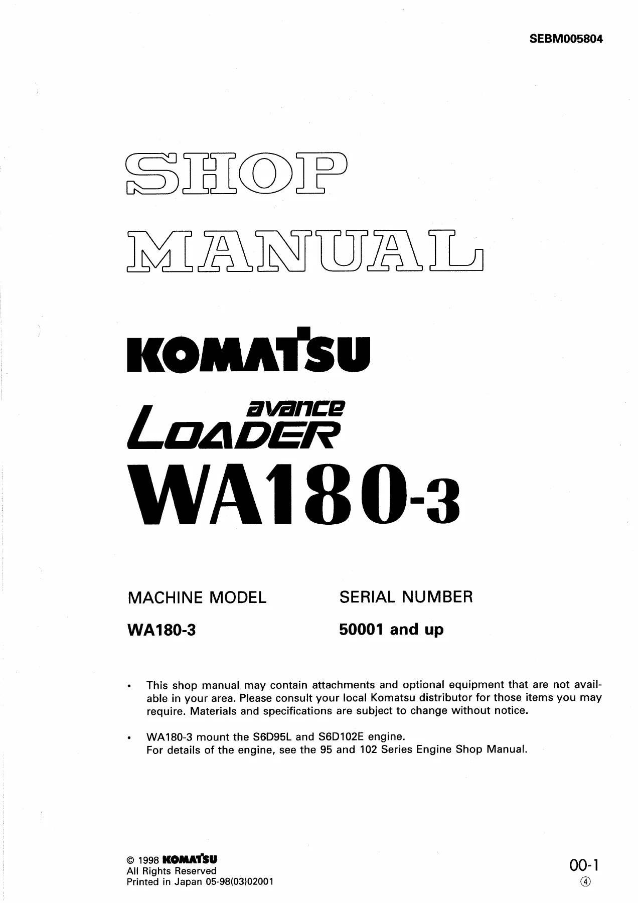
Komatsu WA180-3 Loader Shop Manual – PDF Download
Original price was: $39.95.$24.95Current price is: $24.95.
Komatsu WA180-3 Loader Shop Manual PDF covering serial 50001 and up, S6D95L and S6D102E engines, structure, testing, adjusting, disassembly, assembly, and maintenance standards. Instant download.
Description
Komatsu WA180-3 Loader Shop Manual PDF
This Komatsu WA180-3 Loader Shop Manual is a complete PDF service manual for the WA180-3 loader from serial number 50001 and up. It covers chassis and engine-related testing and adjusting information for machines fitted with the Komatsu S6D95L and S6D102E-1 engines. The manual is organized into general information, structure and function, testing and adjusting, disassembly and assembly, and maintenance standard sections. It is the type of document a service technician uses to diagnose, adjust, repair, and rebuild major loader systems.
File Details
- Manual type: Shop Manual
- Brand: Komatsu
- Model: WA180-3 Loader
- Serial number coverage: 50001 and up; detailed specification tables for 50001-52999 and 53001 and up
- Engines covered: Komatsu S6D95L, Komatsu S6D102E-1
- Language: English
- File format: PDF
- Page count: 608
- Main chapters: 01 General, 10 Structure and Function, 20 Testing and Adjusting, 30 Disassembly and Assembly, 40 Maintenance Standard
Chapters Covered
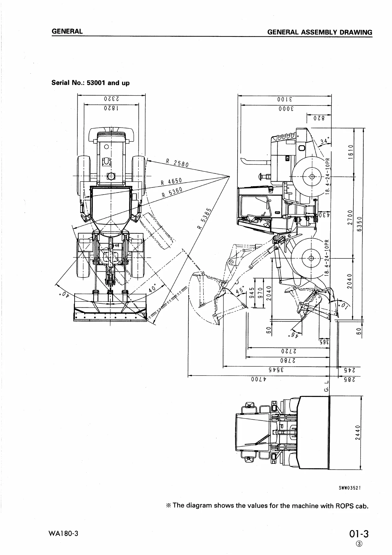
- 01 GENERAL: General assembly drawing, specifications, weight table, list of lubricant and water
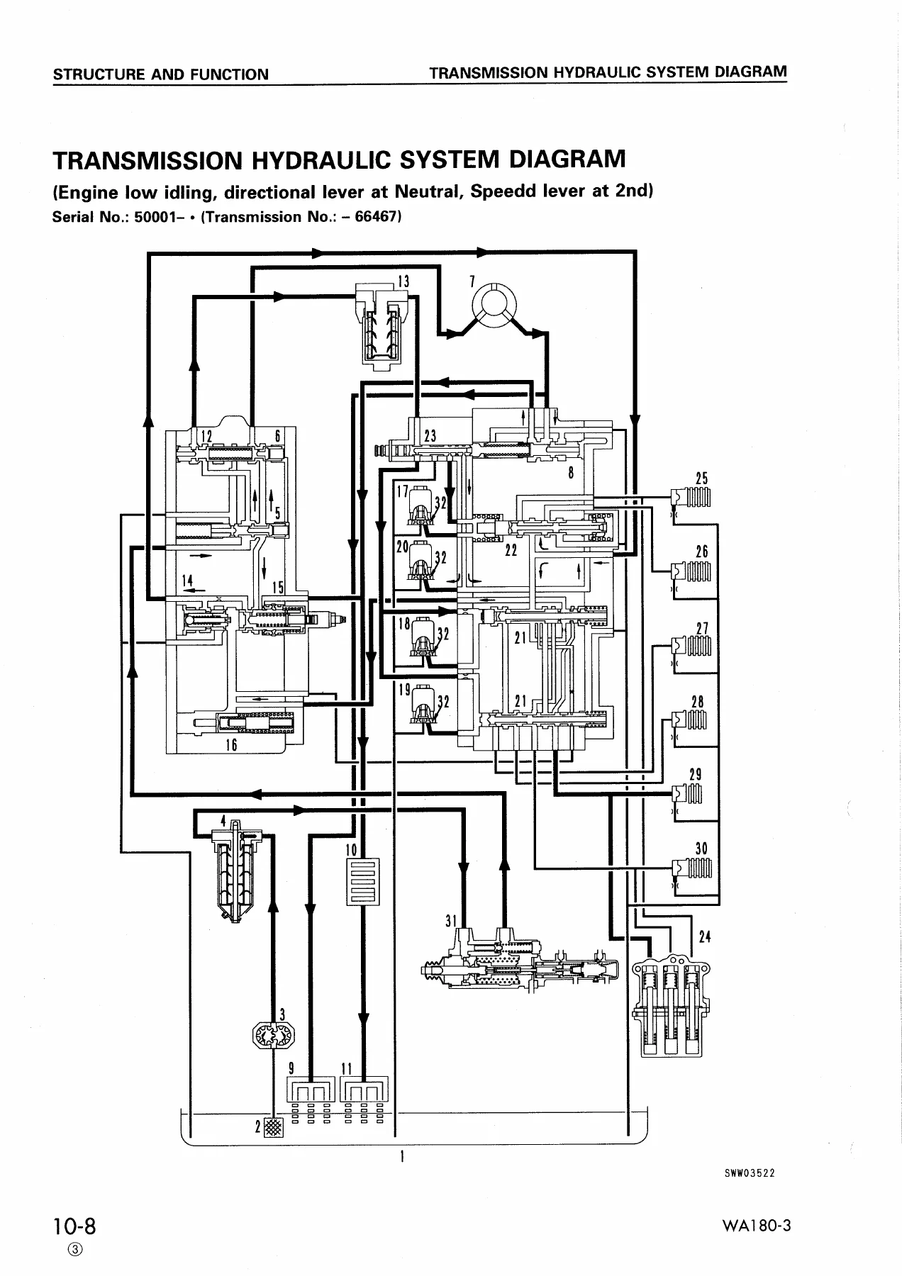
- 10 STRUCTURE AND FUNCTION: Power train system, torque converter, transmission piping, transmission hydraulic system diagram, transmission hydraulic circuit diagram, torque converter oil filter, transmission, transmission control valve, transmission control, drive shaft, axle, final drive, axle mount, center hinge pin, steering piping, steering column, priority valve, cushion valve, steering valve (orbit-roll), brake piping, brake control, brake booster, brake, parking brake control, parking brake, hydraulic piping, work equipment hydraulic system diagram, work equipment hydraulic circuit diagram, hydraulic tank, main control valve, work equipment lever linkage, work equipment linkage, bucket, bucket positioner and boom kick-out, proximity switch, canopy, ROPS cab, ROPS canopy, air conditioner, travel damper system, electrical wiring diagram, electrical circuit diagram, central panel (cluster gauge), sensor, engine starting circuit, engine stop circuit, fuel cut-off solenoid, automatic preheating circuit (Q.G.S. circuit), automatic preheating circuit (Q.H.S. controller), automatic air bleed mechanism, electrical transmission control, combination switch, transmission cut-off function, parking brake function, kick-down switch
- 20 TESTING AND ADJUSTING: Standard value table for engine, standard value table for chassis, tools for testing adjusting and troubleshooting, adjusting valve clearance, measuring compression pressure, testing and adjusting fuel injection timing, measuring exhaust color, measuring blow-by pressure, measuring intake air pressure (boost pressure), measuring engine oil pressure, testing and adjusting fan belt tension, measuring engine speed, method for adjusting engine stop motor cable, adjusting engine stop solenoid, measuring accelerator pedal, measuring operating force and travel of speed lever, measuring stall speed, measuring torque converter and transmission oil pressure, method of operating emergency manual spool, testing and adjusting steering wheel, measuring steering oil pressure, measuring operating force and travel of brake pedal, testing and adjusting brake pedal linkage, measuring brake performance, measuring brake oil pressure, testing for brake disc wear, bleeding air from brake system, measuring parking brake performance, testing and adjusting parking brake linkage, testing parking brake disc wear, measuring parking brake disc wear, measuring work equipment control lever, measuring stroke of work equipment valve spool, measuring work equipment hydraulic pressure, testing and adjusting bucket positioner, testing and adjusting boom kick-out, TROUBLESHOOTING
- 30 DISASSEMBLY AND ASSEMBLY: Removal, installation, disassembly, and assembly procedures for major components
- 40 MAINTENANCE STANDARD: Inspection and judgement standards for disassembled parts
The Komatsu WA180-3 Loader Shop Manual gives a technician the full service picture for this loader. It explains how each major system is built and how it works, provides hydraulic and electrical circuit diagrams, lists testing and adjusting values, shows disassembly and assembly order, and supplies maintenance standards for judging worn parts. Engine overhaul details are not included in this chassis volume; the foreword points to the 95 and 102 Series Engine Shop Manual for complete engine disassembly and assembly. Even so, this PDF contains engine testing and adjusting data, standard value tables, and engine-related troubleshooting information for the S6D95L and S6D102E-1 engines.
What This Shop Manual Helps You Do
Using this Komatsu WA180-3 Loader Shop Manual, you can check and adjust the transmission hydraulic system, test torque converter stall speed, measure clutch pressures, service the priority valve, repair the steering valve, bleed the brake system, inspect brake discs, set the parking brake, and diagnose electrical problems through the wiring and circuit diagrams. It also covers work equipment hydraulics, bucket positioner, boom kick-out, and travel damper circuits. The testing and adjusting chapter includes standard value tables and permissible values, so you can compare measured readings against the manual’s specifications and decide what needs repair or replacement.
IMAGES PREVIEW
Correct service information matters on a loader because incorrect pressures, clearances, or assembly order can cause repeat failures, damage hydraulic components, or create unsafe braking and steering conditions. This Komatsu WA180-3 Loader Shop Manual PDF puts the manufacturer’s structure, function, testing, adjusting, and maintenance standard information in one document. It is delivered as an instant PDF download after payment, can be stored on a computer or mobile device, and can be printed for use in the workshop. No shipping is required.
Reviews
There are no reviews yet.