
Komatsu WA320-6 WA320PZ-6 Wheel Loader Shop Manual SEN04162-13 – PDF Download
Original price was: $49.95.$29.95Current price is: $29.95.
Complete Komatsu shop manual for the WA320-6 and WA320PZ-6 wheel loaders (serial 70001 and up) covering specifications, structure and function, testing and adjusting, troubleshooting, disassembly and assembly, plus hydraulic and electrical diagrams. Instant PDF download.
Description
Komatsu WA320-6 and WA320PZ-6 Wheel Loader Shop Manual – SEN04162-13
This is the complete Komatsu shop manual for the WA320-6 and WA320PZ-6 wheel loaders, serial number 70001 and up, published under form number SEN04162-13. It is the workshop-level reference used for servicing, testing, adjusting, troubleshooting, disassembly and assembly of the entire machine – engine and cooling, power train, steering, brakes, undercarriage and frame, hydraulics, work equipment, cab, and electrical systems. Supplied as an instant-download PDF you can keep on any device and print from the shop floor.
File Details
- Manual type: Shop Manual (service, repair, testing, troubleshooting)
- Brand: Komatsu
- Models: WA320-6, WA320PZ-6
- Serial number: 70001 and up
- Engine: Komatsu SAA6D107E-1
- Form / document number: SEN04162-13
- Language: English
- File format: PDF
- Pages: 1,416
Chapters Covered
The Komatsu WA320-6 WA320PZ-6 shop manual is organised into the following top-level sections and sub-sections:
- 00 Index and foreword – composition of shop manual, safety notice, how to read the shop manual, explanation of terms for maintenance standard, handling of electric equipment and hydraulic components, connectors used for engines, how to read electric wire code, precautions during operation, push-pull coupler procedures, standard tightening torque table, conversion table
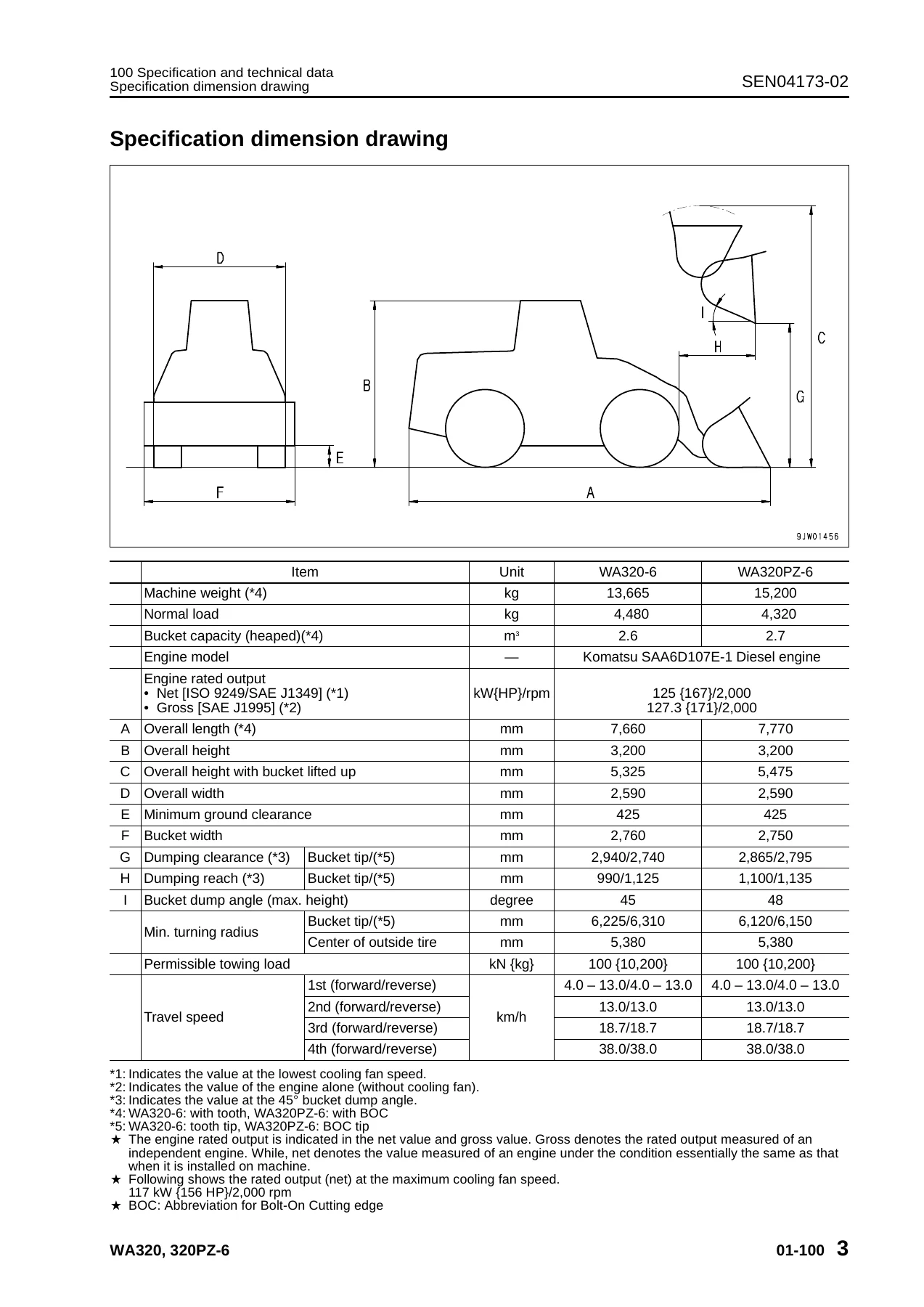
- 01 Specification – specification dimension drawing, specifications, weight table, table of fuel, coolant and lubricants
- 10 Structure, function and maintenance standard
- 100 Engine and cooling system – engine mount and transfer mount, damper, cooling system, cooling system hydraulic piping diagram, cooling fan motor
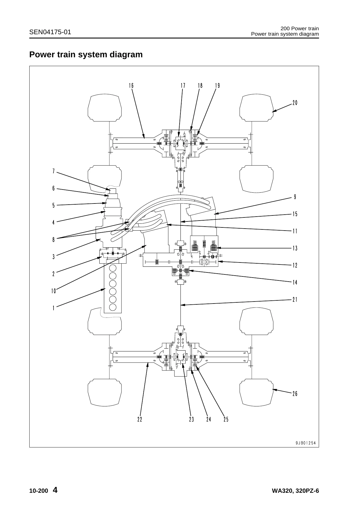
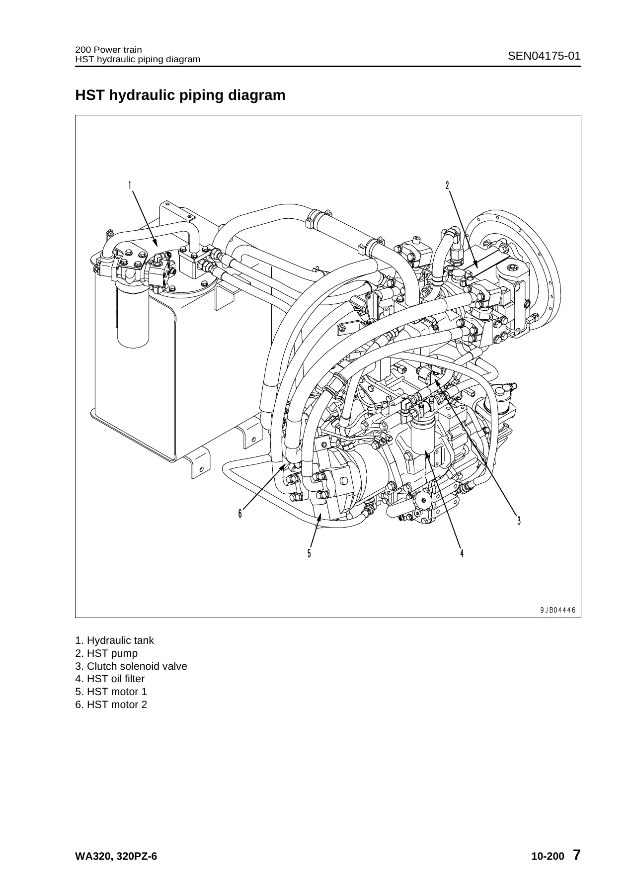
- 200 Power train – power train system diagram, drive shaft, HST hydraulic piping diagram, HST pump, HST motor, transfer, clutch solenoid valve, axle, differential, torque proportioning differential, limited slip differential, final drive
- 300 Steering system – steering piping diagram, steering column, priority valve, orbit-roll valve, cushion valve, steering cylinder, emergency steering piping diagram, emergency steering valve, steering relief valve
- 400 Brake system – brake piping diagram, charge valve, brake valve, inching valve, accumulator, slack adjuster, brake, parking brake control, parking brake
- 500 Undercarriage and frame – axle mount and center hinge pin, tires
- 600 Hydraulic system – work equipment hydraulic piping diagram, work equipment control lever linkage, hydraulic tank, 4-gear pump, work equipment control valve, cut-off valve, PPC valve, lock valve, accumulator, ECSS valve
- 700 Work equipment – work equipment linkage, bucket, bucket positioner and boom kick-out, work equipment cylinder
- 800 Cab and its attachments – cab, air conditioner
- 910 Electrical system, Part 1 – machine monitor system, machine monitor, rearview monitor system
- 920 Electrical system, Part 2 – HST controller system, HST controller, ECSS system, KOMTRAX system, engine starting circuit, engine stopping circuit, preheating circuit, engine output derating function, automatic warm-up function, parking brake circuit, coupler plunger control system, max. traction switch, multi-function knob, sensors
- 20 Standard value table – standard service value table for engine, standard service value table for chassis
- 30 Testing and adjusting – tools for testing, adjusting and troubleshooting; measuring engine speed; measuring exhaust gas color; adjusting valve clearance; measuring compression pressure; measuring blow-by pressure; measuring engine oil pressure; measuring intake air (boost) pressure; handling fuel system equipment; testing and adjusting HST oil pressure; clutch control pressure; steering; hydraulic fan; brake pedal and linkage; accumulator charge pressure; wheel brake oil pressure; brake disc wear; parking brake; work equipment control lever; work equipment hydraulic pressure; work equipment PPC oil pressure; bleeding air; proximity switch checks; diode testing; KOMTRAX terminal operations; rearview camera adjustment; machine monitor adjustment; special functions of machine monitor (EMMS); Pm clinic inspection chart
- 40 Troubleshooting – failure code table and fuse locations; general information on troubleshooting; connection table for connector pin numbers; troubleshooting by failure code (Parts 1 through 7); troubleshooting of electrical system (E-mode); troubleshooting of hydraulic and mechanical system (H-mode); troubleshooting of engine (S-mode)
- 50 Disassembly and assembly – general information; engine and cooling system; power train Part 1 and Part 2; undercarriage and frame; hydraulic system; work equipment; cab and its attachments; electrical system
- 90 Diagrams and drawings – hydraulic diagrams and drawings (automatic greasing circuit, hydraulic circuit), electrical diagrams and drawings (electrical circuit diagram, connector list and stereogram)
The manual as a whole gives the technician a complete, model-specific reference for the WA320-6 and WA320PZ-6. Every major assembly is covered both in terms of how it is built and how it should behave, so that a fault can be diagnosed against a known-good standard, then repaired and reassembled to the correct values.
What this Komatsu WA320-6 WA320PZ-6 shop manual covers in practice
The Structure, function and maintenance standard chapters explain how each system on the machine works and give the wear limits, clearances and service criteria you need when deciding whether a component can be reused or must be replaced. The Standard value table gives the reference figures for a new machine along with the service limits, so comparisons can be made with confidence.
The Testing and adjusting section is built around real measurement jobs: engine speed, exhaust gas color, valve clearance, compression pressure, blow-by pressure, engine oil pressure, boost pressure, fuel pressure and return rate, HST oil pressure, clutch control pressure, steering oil pressure and steering wheel effort, hydraulic fan speed and drive pressure, brake pedal and linkage, accumulator charge pressure, wheel brake oil pressure, brake disc wear, parking brake performance, work equipment control lever, work equipment hydraulic and PPC pressures, plus bleeding and residual-pressure release procedures for each circuit. The Pm clinic inspection chart gathers the routine checks into a single structured sheet.
Troubleshooting and failure codes
The troubleshooting material is one of the largest parts of this manual. It starts with a failure code table and fuse locations, then general troubleshooting guidance, connector pin-number tables, and T-branch adapter references. From there the manual works through troubleshooting by failure code in seven parts, covering machine monitor, engine controller, HST controller, electrical and mechanical codes. Separate mode-based sections handle electrical system faults (E-mode), hydraulic and mechanical faults (H-mode), and engine faults (S-mode), so a symptom such as poor starting, slow travel, weak traction, heavy steering, brake drag, or a lift arm that will not hold can be traced through a defined path rather than by guesswork.
Disassembly and assembly
The disassembly and assembly volume covers the full machine in a stepwise fashion – from the fuel supply pump, injectors and cylinder head, through radiator, aftercooler, hydraulic oil cooler and engine assembly removal; transfer and parking brake; front and rear axle; center hinge pin and counterweight; HST pump, HST motors, work equipment control valve, hydraulic tank and cylinders; work equipment assembly; operator’s cab, glass and air conditioner; and the electrical components including monitor panel and controllers. Tightening torques, coating materials, special tools and weight notes are given alongside the procedures.
Wiring and hydraulic diagrams
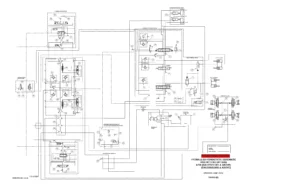
The diagrams section provides the hydraulic circuit diagram, automatic greasing circuit diagram, the electrical circuit diagram in multiple sheets (including common and model-specific versions), and a connector list with stereogram views – useful when tracing a fault through the harness or confirming a circuit before repair.
Who this manual is for
Independent workshops, fleet maintenance teams, and owner-operators who maintain their own Komatsu WA320-6 or WA320PZ-6 wheel loader will find this shop manual supports scheduled servicing, fault finding, component overhaul, and rebuild work on the machine. The coverage applies to serial numbers 70001 and up and to both the standard WA320-6 and the WA320PZ-6 parallel-linkage variant.
Why it matters
Working from the correct figures and procedures keeps the machine within specification, avoids damage caused by using the wrong torque, clearance, or fluid, and shortens the time spent on diagnosis. The manual is written around the SAA6D107E-1 engine and the HST-based drive system used on these models, so the values and steps match the machine on the floor rather than a generic reference.
Delivery
IMAGES PREVIEW
The Komatsu WA320-6 WA320PZ-6 wheel loader shop manual is delivered as an instant-download PDF. There is no shipping and no waiting – the file is available as soon as payment is completed. It can be read on a laptop, tablet or phone in the workshop, and printed pages can be taken straight to the machine for reference during the job.

Reviews
There are no reviews yet.