
Komatsu WA430-6 Shop Manual PDF – KOHAG Specification VEBM350100 (H50051 & Up)
Original price was: $79.95.$49.95Current price is: $49.95.
Complete Komatsu WA430-6 shop manual for KOHAG specification machines, serial H50051 and up. Covers engine, transmission, axles, steering, brakes, hydraulics, and electrical systems with testing, adjusting, and disassembly procedures. 1,339-page PDF.
Description
Komatsu WA430-6 Shop Manual – KOHAG Specification VEBM350100
This is the complete Komatsu WA430-6 shop manual covering KOHAG specification machines from serial number H50051 and up. The manual covers the SAA6D114-2 engine and provides the full range of service, repair, and diagnostic information needed to maintain this wheel loader in the field or workshop. Everything is delivered as a single PDF file that can be viewed on any device and printed when needed.
File Details
- Manual type: Shop Manual
- Brand: Komatsu
- Model: WA430-6
- Serial number: H50051 and up
- Engine: SAA6D114-2
- Specification: KOHAG
- Document number: VEBM350100
- Language: English
- Page count: 1,339
- File format: PDF
Chapters Covered
- 00 SAFETY
- 01 GENERAL
- 10 STRUCTURE AND FUNCTION
- 20 TESTING AND ADJUSTING
- 30 DISASSEMBLY AND ASSEMBLY
- 90 OTHERS
00 SAFETY
Safety notices and general precautions for servicing the WA430-6. Covers personal protective equipment, safe work practices for two-person operations, preparation before greasing or repairs, handling of hot coolant and oil, battery lead removal sequence, lifting heavy components, and high-pressure hose installation. Includes hoisting instructions with wire rope load tables and sling angle capacity charts.
01 GENERAL
Machine specifications for the WA430-6 with the SAA6D114-2 engine, including rated output, torque, displacement, bore and stroke, and fuel consumption. Contains the weight table for major components, the fuel/coolant/lubricants table with capacities, and tire specifications. Also covers conversion tables, standard tightening torques for metric bolts, flared nuts, split flange bolts, O-ring boss piping joints and plugs, and hose torque tables. Electric wire color codes and the conversion table for millimeters to inches, kilograms to pounds, liters to gallons, and temperature scales are included.
10 STRUCTURE AND FUNCTION
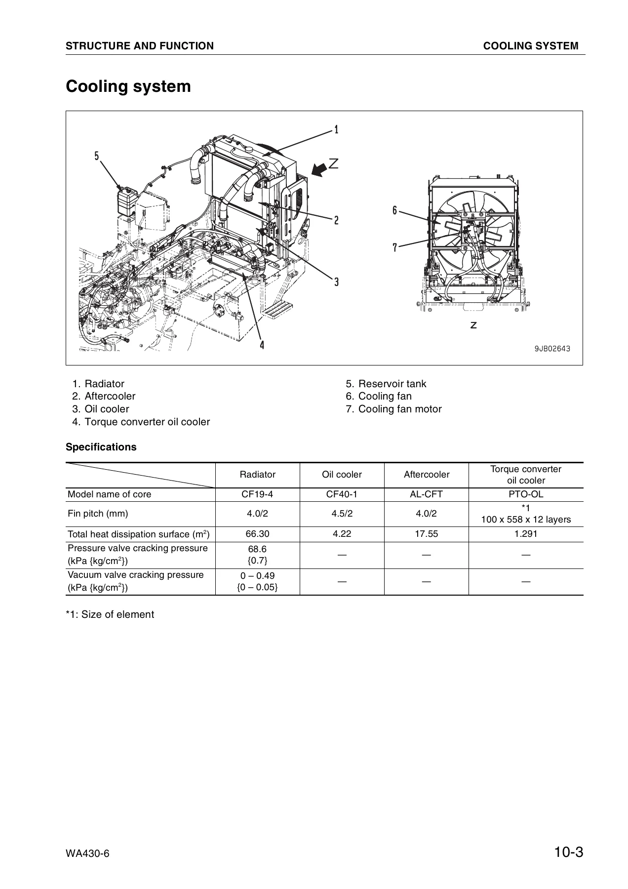
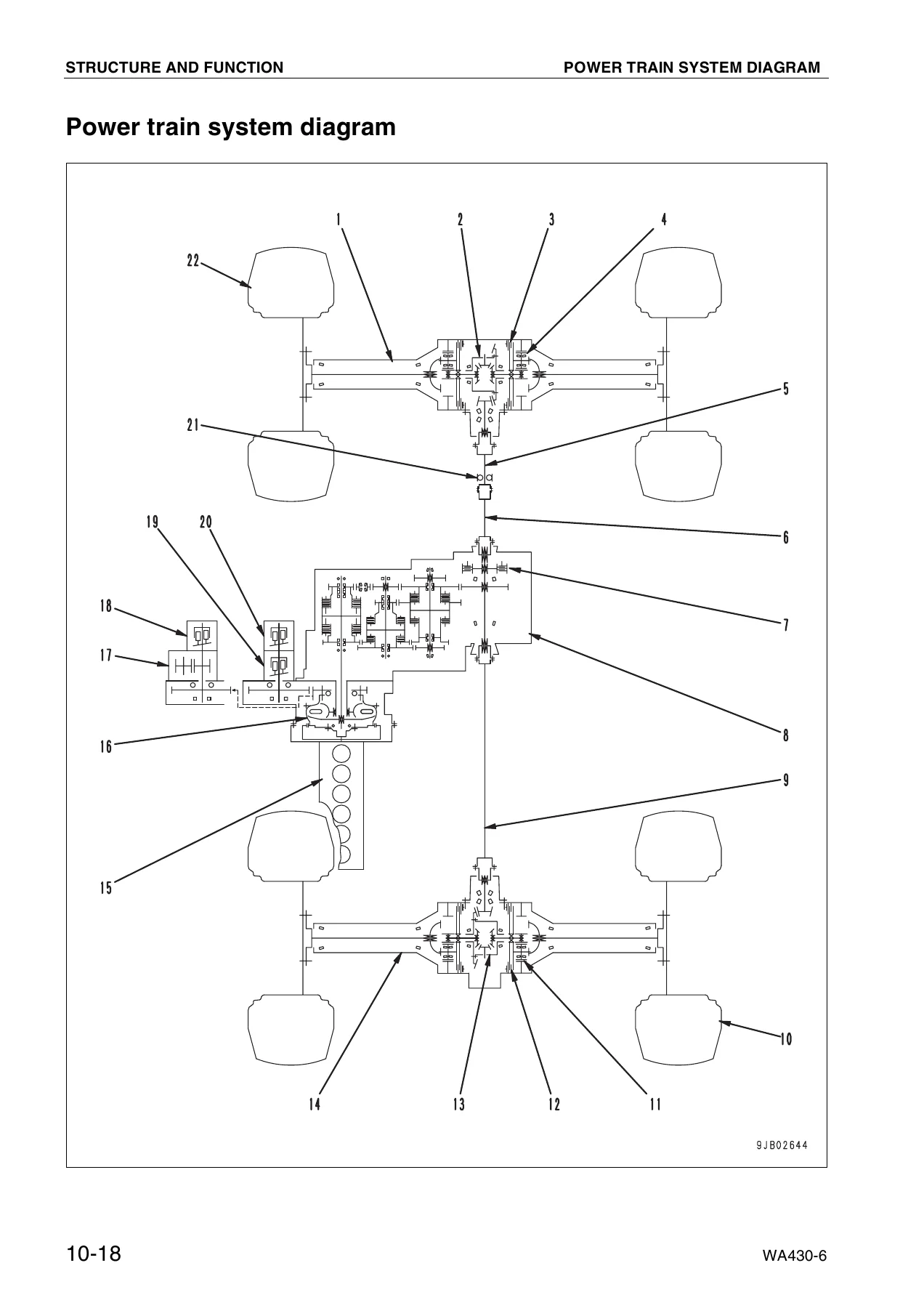
Detailed explanation of how each major system and component on the WA430-6 works. Covers the engine mount and transmission mount, cooling system with radiator, aftercooler, oil cooler, and cooling fan motor, power train unit with torque converter and transmission, axles with differential and limited slip differential, final drive, steering system with steering column, steering pump, steering valve, orbit-roll valve, stop valve, steering relief valve, steering cylinder, and emergency steering. Also covers the brake piping, charge valve, brake valve, accumulator, wheel brake, parking brake control, parking brake, and parking brake solenoid valve. The hydraulic system section covers the work equipment control valve, CLSS, PPC valve, stabilizer valve, bypass valve, lock valve, accumulators, work equipment EPC valve, and work equipment cylinders. The cab, air conditioner, machine monitor system, transmission controller system, work equipment controller system, electric transmission control, engine starting circuit, engine stopping circuit, preheating and post-heating circuit, engine power mode selector circuit, turbocharger protection function, torque derating function, automatic warm-up function, parking brake circuit, and sensors are all covered in detail. Hydraulic circuit diagrams, electric circuit diagrams, and maintenance standards are included.
20 TESTING AND ADJUSTING
Standard value tables for the engine and chassis with measurement conditions, standard values for new machines, and service limit values. Covers testing and adjusting engine speed, measuring exhaust gas color, measuring exhaust temperature, adjusting valve clearance, measuring blow-by pressure, measuring engine oil pressure, measuring intake air (boost) pressure, adjusting engine speed sensor, testing and adjusting air conditioner compressor belt tension, bleeding air from fuel circuit, adjusting accelerator pedal potentiometer and microswitch, adjusting transmission speed sensor, measuring directional lever, testing and adjusting power train oil pressure, flushing procedure for torque converter and transmission hydraulic circuit, method of moving machine when transmission valve is broken, testing and adjusting steering control, steering wheel, and steering oil pressure, bleeding air from steering circuit, testing hydraulic drive fan, bleeding air from fan motor circuit, measuring brake pedal, measuring brake performance, testing and adjusting accumulator charge pressure, testing wheel brake oil pressure, measuring wear of wheel brake disc, bleeding air from wheel brake circuit, releasing residual pressure in brake accumulator circuit, testing parking brake performance, measuring parking brake oil pressure, testing wear of parking brake disc, method of releasing parking brake manually, measuring and adjusting work equipment control lever, testing and adjusting work equipment PPC oil pressure and work equipment oil pressure, bleeding air from work equipment circuit, releasing residual pressure in work equipment circuit, testing and adjusting bucket positioner and boom kick-out, checking proximity switch operation pilot lamp, procedure for testing diodes, adjusting machine monitor, special functions of machine monitor, and the PM Clinic inspection table.
30 DISASSEMBLY AND ASSEMBLY
Procedures for removing, installing, disassembling and assembling major components of the WA430-6. Covers removal and installation of fuel injection pump assembly, fuel injector assembly, cylinder head assembly, radiator assembly, engine assembly, engine hood assembly, fuel tank assembly, parking brake disc and plate, torque converter and transmission assembly, disassembly and assembly of transmission assembly, transmission clutch pack assembly, parking brake assembly, torque converter assembly, removal and installation of front axle assembly, rear axle assembly, disassembly and assembly of axle housing assembly, differential assembly, removal and installation of steering valve assembly, hydraulic tank assembly, disassembly and assembly of hydraulic cylinder, removal and installation of work equipment, operator’s cab assembly, operator’s cab glass (stuck glass), operator’s cab and floor frame assembly, center hinge pin, counterweight, and air conditioner unit. Each section includes special tools, tightening torques, coating agents, and precautions.
90 OTHERS
Power train hydraulic circuit diagram, engine electrical circuit diagram, hydraulic circuit diagram, and the complete electrical circuit diagram split into 8 sections. These diagrams show the full hydraulic and electrical routing for the WA430-6, including connector pin numbers, wire colors, and component locations.
What This Manual Enables You To Do
With this Komatsu WA430-6 shop manual on hand, you can perform the full range of service and repair tasks on this wheel loader. The engine section covers the SAA6D114-2 from valve clearance adjustment to fuel injection pump removal. The power train chapters walk through torque converter and transmission disassembly with clutch pack specifications and bearing adjustment procedures. The axle and differential sections provide the shimming and preload values needed for a correct rebuild. The brake chapter covers both the wet disc service brakes and the transmission output shaft parking brake. The hydraulic section details the CLSS system, PPC valves, and work equipment control valve with testing and adjusting values. The electrical section includes the machine monitor, transmission controller, work equipment controller, and all sensor circuits with connector pin numbers and failure codes.
Why Correct Procedures and Specs Matter
Heavy equipment repair is unforgiving. A bearing preload set outside the standard range, a clutch pack assembled without the correct clearance, or a hydraulic relief valve adjusted to the wrong pressure will lead to premature failure, costly downtime, and possible safety incidents. This manual gives you the exact specifications, tightening torques, and step-by-step procedures that Komatsu specifies for the WA430-6. The testing and adjusting chapter helps you diagnose problems before disassembly, and the troubleshooting sections for the transmission controller, work equipment controller, and machine monitor help you trace electrical faults to the exact circuit.
IMAGES PREVIEW
Instant PDF Delivery
The manual is delivered as a PDF file immediately after purchase. No shipping, no waiting. You can view it on a laptop, tablet, or smartphone, and print any page or section you need for the workshop. Whether you are servicing the engine, rebuilding the transmission, troubleshooting an electrical fault, or adjusting the brakes, this Komatsu WA430-6 shop manual is the reference you need to get the job done correctly.

Reviews
There are no reviews yet.