
Komatsu WA470-5H & WA480-5H Wheel Loader Shop Manual – Complete PDF Service & Repair Guide
Original price was: $82.45.$54.95Current price is: $54.95.
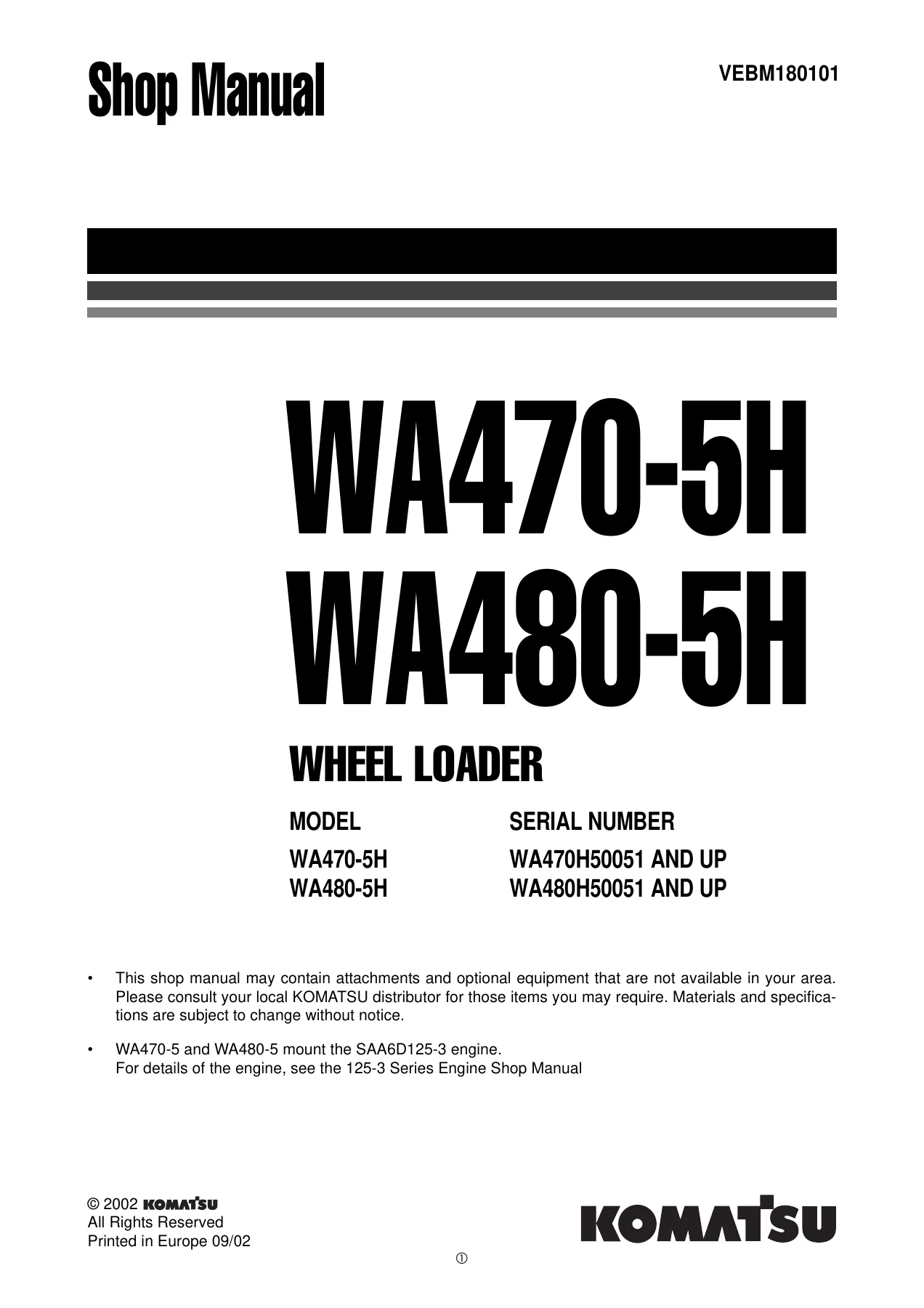
Complete Komatsu shop manual for WA470-5H and WA480-5H wheel loaders (serial WA470H50051 and up, WA480H50051 and up). Covers engine, powertrain, axles, brakes, steering, hydraulics, work equipment, testing and adjusting, disassembly and assembly, plus wiring and hydraulic circuit diagrams. Instant PDF download.
Description
Komatsu WA470-5H & WA480-5H Shop Manual – Your Complete Workshop Reference
This is the full Komatsu shop manual for the WA470-5H and WA480-5H wheel loaders, covering serial numbers WA470H50051 and up and WA480H50051 and up. Whether you are a professional technician, a fleet maintenance manager, or an owner-operator who prefers to handle repairs in-house, this manual gives you the same structured procedures, specifications, and diagrams used in a Komatsu service workshop. It is not a generic guide – it is the complete, model-specific documentation for these two machines.
File Details
- Manual Type: Shop Manual (Service, Repair, Testing & Adjusting, Disassembly & Assembly)
- Brand: Komatsu
- Models Covered: WA470-5H, WA480-5H
- Serial Numbers: WA470H50051 and up; WA480H50051 and up
- Engine: SAA6D125E-3
- Language: English
- File Format: PDF
- Document Number: VEBM180101
- Publication Date: September 2002
- Page Count: Approximately 1,300 pages
Chapters Covered
- 00 Safety
- 01 General
- 10 Structure and Function, Maintenance Standard
- 20 Testing and Adjusting
- 30 Disassembly and Assembly
- 90 Appendix
00 Safety
Opens with the safety notice and general precautions that apply before any greasing or repair work begins. It details the preparations needed before starting a job, precautions to observe during work, and how to read the shop manual correctly – including the filing method, revised edition marks, and the symbols used throughout the manual to flag safety, caution, weight, tightening torque, coating, oil/water, and drain points. The hoisting instructions section covers wire rope selection based on part weight, correct slinging techniques, and the effect of sling angle on load capacity. A coating materials chart lists the recommended adhesives, gasket sealants, and lubricants with their part numbers and applications. The standard tightening torque tables give values for bolts and nuts by thread diameter, hose nuts by nominal size, split flange bolts, flared nuts, and the specific torque values for the 102 engine series including eye joints and tapered screws. Electric wire coding, conversion tables for millimetres to inches, kilograms to pounds, litres to U.S. gallons, kgm to ft.lb, kg/cm² to lb/in², and a Fahrenheit/Centigrade temperature conversion table round out this section.
01 General
Presents the general machine dimensions for both models – overall length, overall height, overall height with the bucket raised, overall width, minimum ground clearance, bucket width, dumping clearance, dumping reach, and bucket dump angle – alongside a full specification table covering the engine, power train, axle, wheel, brakes, steering, hydraulic pumps, and cylinder dimensions. A weight table lists the individual weights of major components including the engine, radiator, transmission, torque converter, drive shafts, axles, wheels, tyres, steering components, hydraulic tank, pumps, valves, cylinders, frames, bucket link, bell crank, boom, bucket, counterweight, fuel tank, battery, cab, and air conditioner unit. The lubricant and coolant list gives the recommended engine oil, axle oil, diesel fuel, grease, and coolant with ambient temperature ranges and capacities for the engine oil pan, transmission case, hydraulic system, axle, fuel tank, and cooling system.
10 Structure and Function, Maintenance Standard
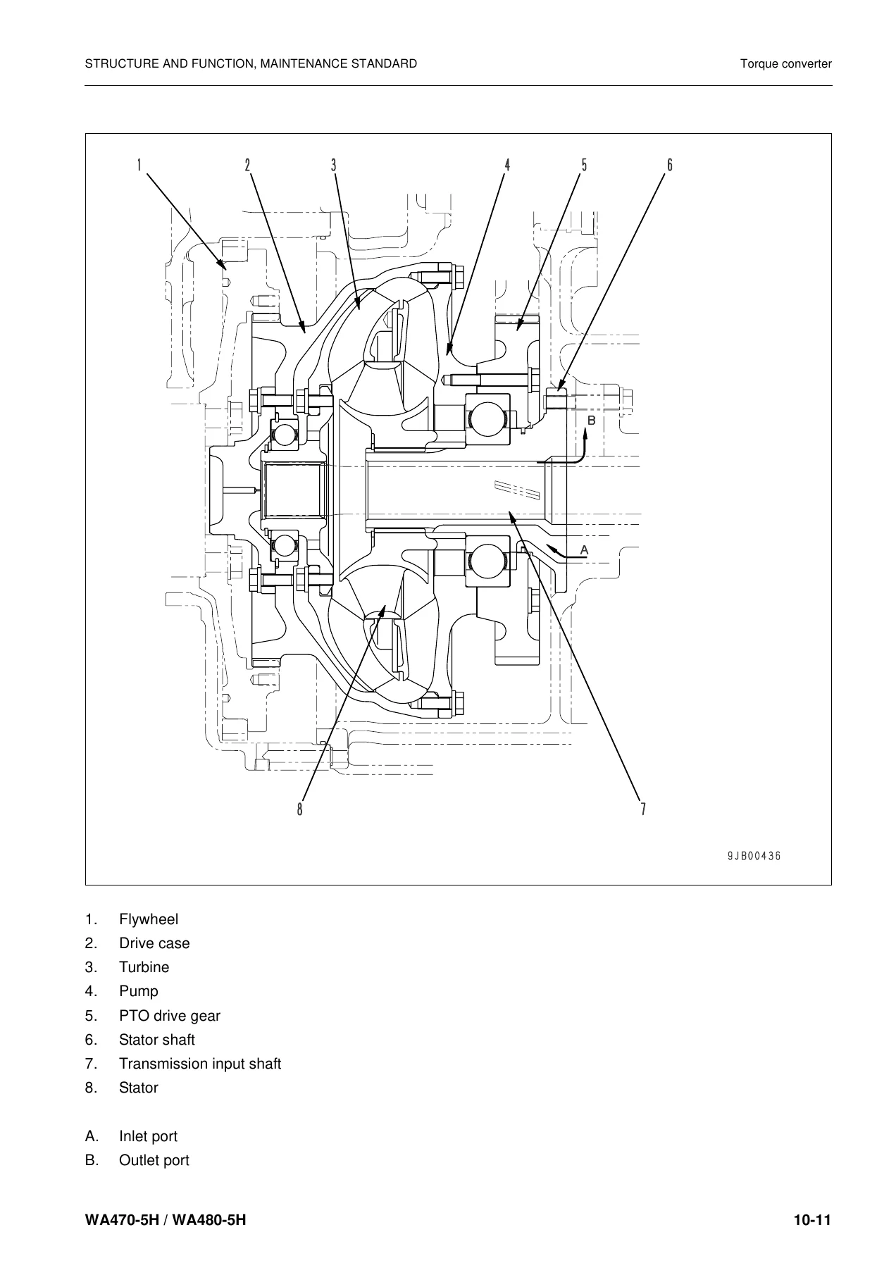
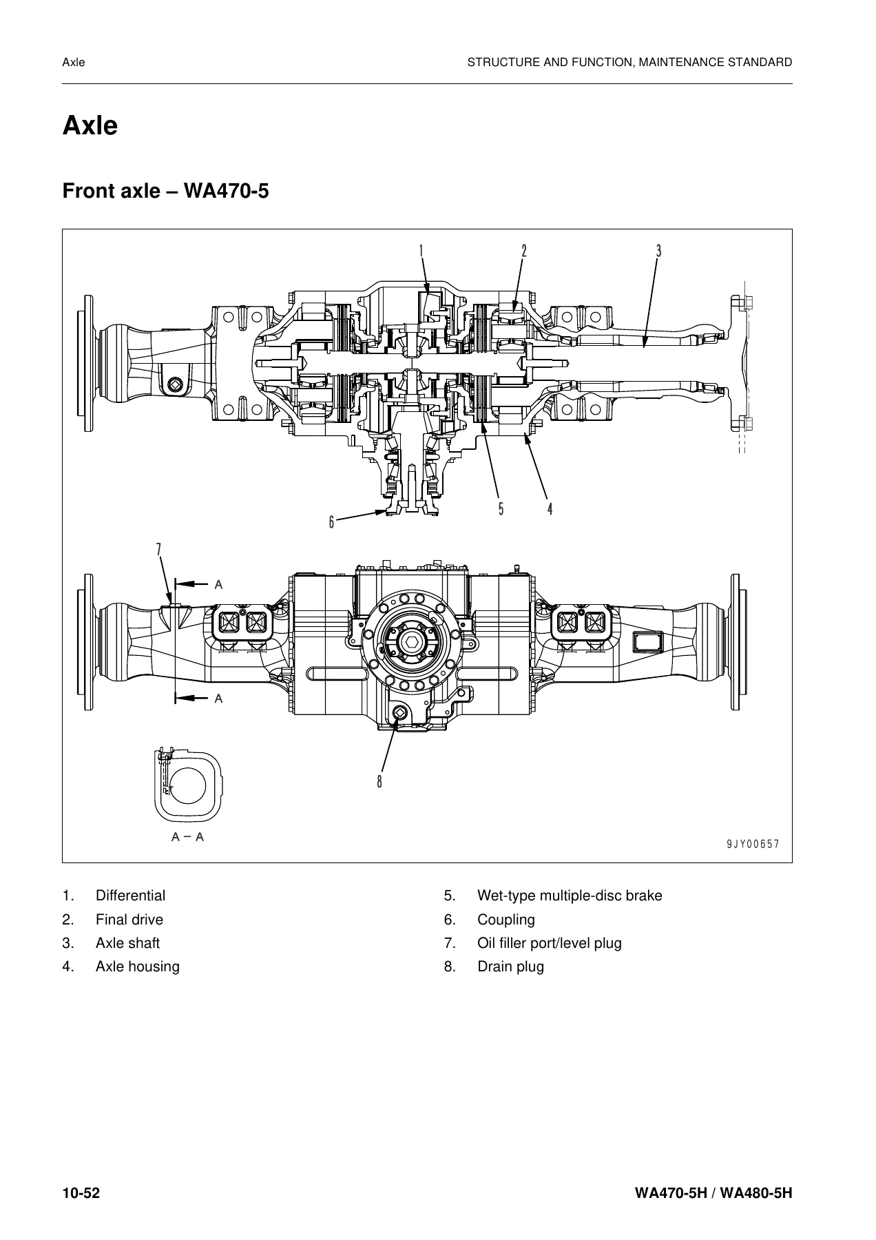
This is the largest chapter and explains how each major system on the WA470-5H and WA480-5H is built and how it works. It covers the radiator, aftercooler, oil cooler, and cooling fan, followed by the engine and transmission mounts with clearance checks. The power train section includes the system diagram, drive shaft (propeller shaft) layout, torque converter and transmission piping, torque converter operation with and without the lock-up clutch, transmission gear train and clutch operation, transmission control valve with ECMV actuation tables, main relief and torque converter relief valves, flow control valve, axle assemblies (front and rear, with and without anti-slip differential), differential operation, final drive planetary gears, axle mounting and centre hinge pin, steering piping, steering column and orbit-roll, steering valve with overload relief, steering relief, demand valve operation, flow amp, steering pump and switch pump, emergency steering pump and motor (option), steering cylinder, joystick steering lever (option), steering switch valve (option), brake piping, brake valves (left and right), charge valve, accumulator, slack adjuster, wheel brakes (front and rear), parking brake control, parking brake, parking brake solenoid valve, parking brake emergency release valve, hydraulic piping, work equipment control lever (PPC and EPC), hydraulic tank and breather, torque converter charging, work equipment and PPC pumps, PPC relief valve, travel damper valve (option), work equipment control valve (2-spool and 3-spool), PPC valve, work equipment control EPC valve (option), shut-off valve (option), cooling fan motor (LMF28), cooling fan motor drive pump (LPV30), servo valve, safety valve, work equipment linkage, bucket, bucket positioner and lift arm kick-out, work equipment cylinders (lift arm and bucket), cab (option), air conditioner (option), machine monitoring system with circuit diagrams, sensing functions, power supply and network, machine monitor layout, load meter specifications (option), monitor indication table, machine monitor settings, transmission control system, transmission controller, work equipment control system (option), electric transmission control, combination switch, kick down and hold switches, engine starting and stopping circuits, parking brake circuit, turn signal and hazard lamp circuit, backup lamp and stop lamp circuit, small lamp and headlamp circuit, working lamp circuit, horn circuit, windshield wiper and washer circuit, sensors, and relays. Every system is accompanied by maintenance standard tables with check items, criteria, standard sizes, tolerances, standard clearances, clearance limits, and remedies.
20 Testing and Adjusting
Begins with the standard value table for the engine and the standard value table for the chassis – both giving measurement conditions, units, standard values for a new machine, and service limit values. The testing and adjusting section gives step-by-step procedures for measuring engine speed (low idling, high idling, torque converter stall, hydraulic stall, and full stall), measuring exhaust colour and exhaust temperature, adjusting valve clearance, measuring compression pressure, measuring blow-by pressure, measuring engine oil pressure, measuring air supply pressure (boost pressure), measuring fuel pressure, adjusting the engine speed sensor, handling fuel system equipment, releasing remaining fuel pressure, bleeding air from the fuel circuit, reduced cylinder mode operation for the engine, checking for fuel leakage, adjusting the accelerator pedal potentiometer and microswitch, adjusting the transmission speed sensor, testing and adjusting power train oil pressure (main relief, torque converter relief, torque converter outlet, transmission clutch pressures, lock-up clutch pressure, and parking brake pressure), flushing the torque converter and transmission hydraulic circuit, moving the machine when the transmission valve fails, testing and adjusting steering control and steering oil pressure, measuring brake oil pressure, testing wear of the wheel brake disc, bleeding air from the brake circuit, testing wear of the parking brake disc, manual release method for the parking brake, testing and adjusting accumulator charge pressure, testing and adjusting PPC oil pressure, testing and adjusting work equipment hydraulic pressure, testing and adjusting the bucket positioner and lift arm kick-out, checking proximity switch actuation pilot lamp, adjusting the machine monitor with rotary switch and dipswitch settings, testing and adjusting the load meter, bleeding air, releasing remaining pressure in the hydraulic circuit and travel damper circuit, and handling the controller high-voltage circuit.
30 Disassembly and Assembly
Provides the removal, installation, disassembly, and assembly procedures for the major components. It opens with the method of using the manual and the precautions to be observed during removal, installation, and completion of operations. Component-specific sections cover the fuel supply pump assembly, nozzle holder assembly, nozzle tip, cylinder head assembly, radiator assembly, air aftercooler assembly, cooling fan drive motor, engine assembly, steering pump/switch pump/cooling fan drive pump assembly, torque converter charge/work equipment/PPC pump assembly, torque converter and transmission assembly, torque converter assembly (standard and lock-up specifications), transmission assembly, transmission clutch pack assembly, parking brake assembly, front axle assembly, rear axle assembly, axle housing assembly, differential assembly, centre hinge pin, steering valve assembly, travel damper assembly, parking brake disc, hydraulic tank, work equipment valve assembly, hydraulic cylinder assembly (steering, lift, and bucket), work equipment assembly, counterweight, fuel tank assembly, cab assembly, cab/floor frame assembly, air conditioner unit assembly, and air conditioner compressor assembly. Each procedure includes the special tools required, the sequence of removal or disassembly, the inspection points, the installation or assembly sequence, and the specified tightening torques, adhesives, and sealants.
90 Appendix
Contains the work equipment hydraulic circuit diagram (standard and for electric work equipment lever), power train oil circuit diagram (with and without torque converter lock-up clutch), brake oil circuit diagram, the complete electric circuit diagram in eight sections covering the entire machine, engine control system diagram, transmission control system diagram, work equipment control system diagram, monitor system diagram, and the electrical system diagram.
What This Komatsu Shop Manual Enables You to Do
This manual is not a light overview – it is the full workshop documentation for the WA470-5H and WA480-5H. With it, you can diagnose and repair the SAA6D125E-3 engine, service the torque converter and transmission, adjust the main relief and torque converter relief valves, test clutch pressures, inspect and rebuild the front and rear axles, differentials, and final drives, service the wet-type multiple-disc brakes, adjust the parking brake, troubleshoot the steering system including the orbit-roll and steering valve, test and adjust the PPC and EPC work equipment controls, service the lift arm and bucket cylinders, and work through the machine monitoring system, transmission control system, and work equipment control system with the aid of the circuit diagrams in the appendix. The testing and adjusting section alone gives you the measured values, service limits, and step-by-step procedures you need to make accurate judgments rather than guesswork.
When you are tightening a cylinder head, adjusting valve clearance, setting the accumulator charge pressure, measuring brake oil pressure, or shimming a differential, the exact torque, clearance, or pressure matters. This manual provides those values in table form alongside the procedures, so you are not relying on generic figures or memory. The disassembly and assembly section names the special tools required for each job and gives the installation sequence with the correct adhesives and sealants, which helps avoid comeback repairs caused by incorrect assembly.
IMAGES PREVIEW
Delivered as an instant PDF download, the manual is available immediately after payment – no shipping, no waiting. It can be viewed on a laptop, tablet, or smartphone in the workshop, and pages can be printed for use at the machine. Whether you are carrying out a scheduled service, diagnosing a fault, or rebuilding a major component, this Komatsu WA470-5H and WA480-5H shop manual is the reference that keeps the job moving.
Reviews
There are no reviews yet.