
Komatsu WA500-8 Wheel Loader Shop Manual CEBM030802 – Repair & Service PDF
Original price was: $39.95.$24.95Current price is: $24.95.
Complete Komatsu WA500-8 Wheel Loader Shop Manual (CEBM030802) covering the SAA6D140E-7 engine, power train, hydraulics, steering, brakes, electrical, Urea SCR system, testing and adjusting, troubleshooting, disassembly and assembly, maintenance standards and full circuit diagrams.
Description
Komatsu WA500-8 Wheel Loader Shop Manual – CEBM030802
This is the complete Komatsu WA500-8 Wheel Loader Shop Manual, document number CEBM030802, applicable to machines from serial number A96001 and up and powered by the Komatsu SAA6D140E-7 diesel engine (also listed as the 6D140E-7). The manual is written in English and delivers the full workshop-level service information for the machine — from specifications and structure and function, through testing and adjusting, into troubleshooting by failure code, disassembly and assembly, maintenance standards and the full hydraulic and electrical circuit diagrams.
File Details
- Manual type: Shop Manual
- Brand: Komatsu
- Model: WA500-8 Wheel Loader
- Engine: Komatsu SAA6D140E-7 (6D140E-7)
- Document number: CEBM030802
- Serial numbers: WA500-8 A96001 and up
- Language: English
- File format: PDF
- Page count: 3730 pages
Chapters Covered
- 00 Index and Foreword — abbreviation list, safety notice for operation, precautions to prevent fire, actions if fire occurs, disposal of waste materials, exhaust gas regulations, DEF handling and storage, handling hydraulic equipment, disconnection and connection of pipings, handling electrical equipment, fuel system, intake system, KOMTRAX, push-pull couplers, connector procedures, electrical wire codes, maintenance standard terms, standard tightening torque tables, conversion tables
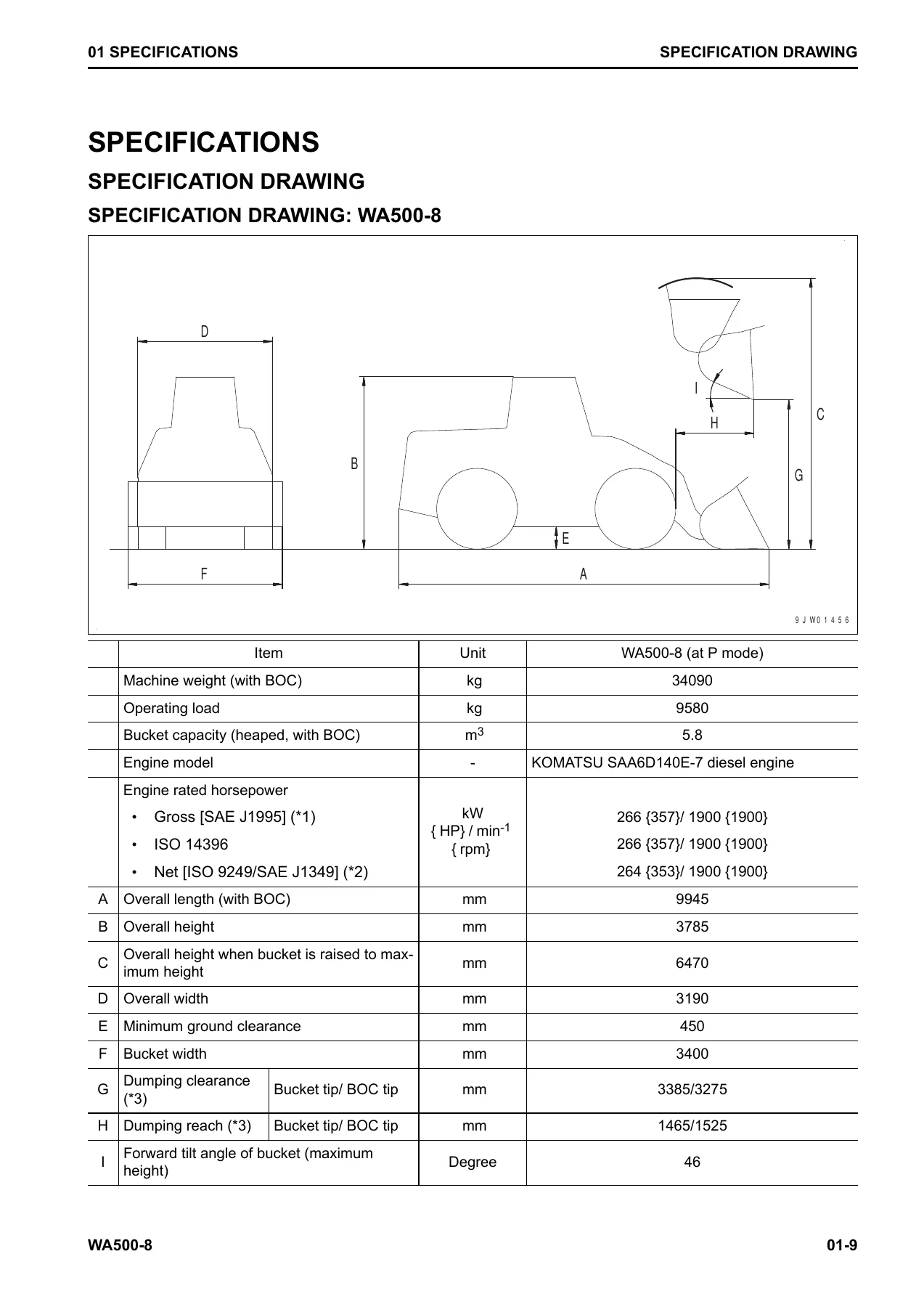
- 01 Specifications — specification drawing, machine specifications, weight table, table of fuel, coolant and lubricants
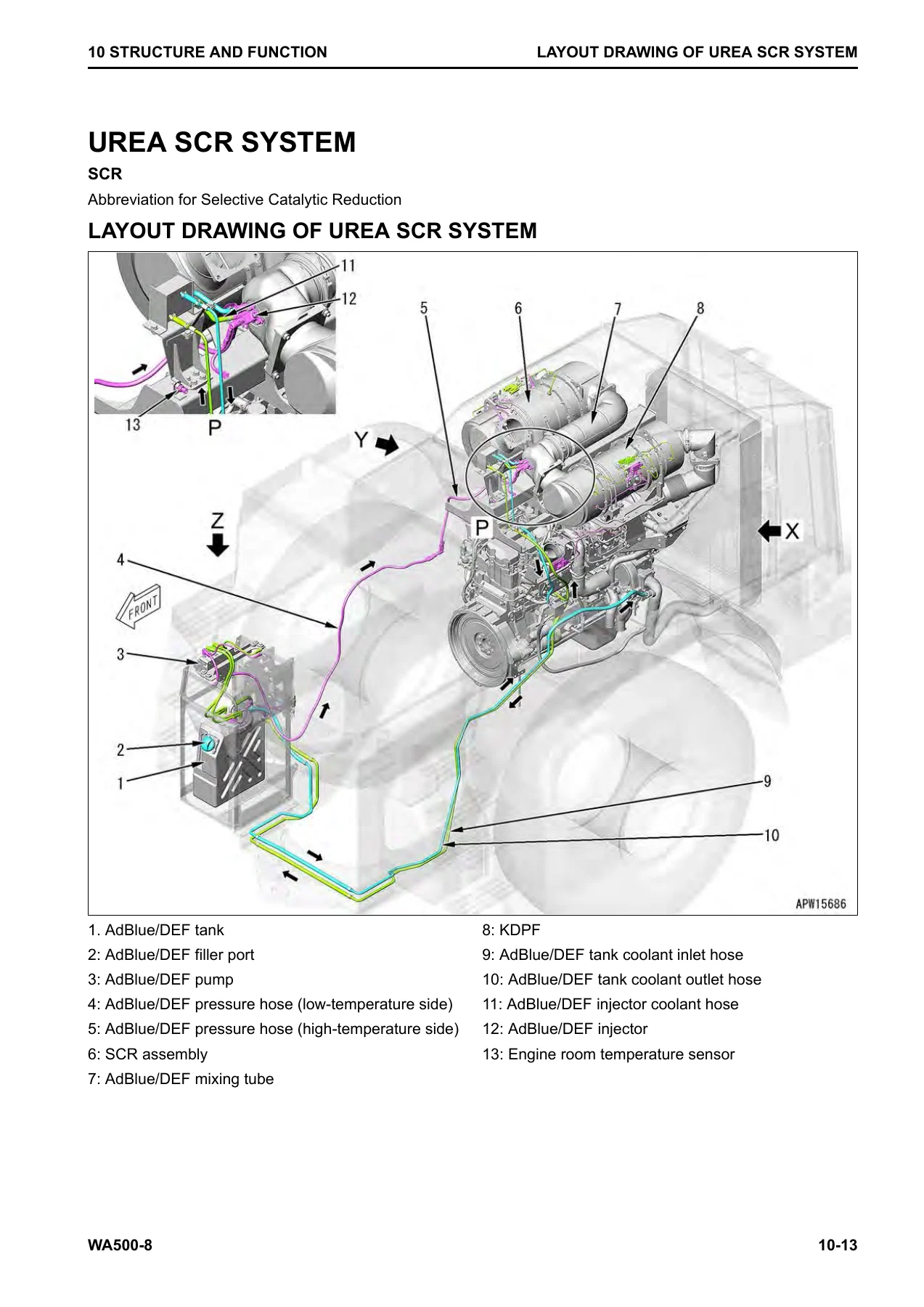
- 10 Structure and Function — Urea SCR system (layout, diagram, function, AdBlue/DEF system, inducement strategy, component parts), boot-up system, system operating lamp, battery disconnect switch, preheating system, engine shutdown secondary switch, engine system and engine control, engine power mode selector, automatic idle stop, RPM set, joint, VGT, EGR system, EGR valve, EGR cooler, KCCV system, KDPF, cooling system, cooling fan control, brake and cooling fan pump, cooling fan motor, control system, machine monitor, rearview monitor, KOMTRAX, load meter, component parts of control system, hydraulic system, CLSS, work equipment pump control, hydraulic tank, work equipment pump, steering pump, power train charge duplex pump, control valve, power train system, transmission control, transmission gear shift control, protection functions, directional selector, transmission cut-off, torque converter, lockup clutch ECMV, transmission, transfer, regulator and relief valves, axle, differentials, final drive, work equipment system, work equipment control, neutral lock, remote positioner, bucket and boom positioner, auto-digging, ECSS, steering system, secondary steering, joystick steering, AJSS, steering column, brake system, parking brake control, charge valve, parking brake solenoid valve, emergency release valve, brake accumulator, brake valve, slack adjuster, brake, parking brake, auto-greasing system, undercarriage and frame, tires, work equipment structure, ROPS cab
- 20 Standard Value Table — engine and machine standard values, machine posture and procedure for measuring performance
- 30 Testing and Adjusting — engine speed, boost pressure, exhaust gas temperature and color, valve clearance, compression pressure, blowby pressure, engine oil pressure, EGR valve and VGT oil pressure, fuel pressure, fuel return rate and leakage, bleeding fuel system, fuel circuit leakage test, cylinder cut-out mode, no-injection cranking, KDPF/SCR/muffler inspection, cylinder head and manifold installation, engine piping, fuel doser cleaning, injector compensation writing, ash in soot correction, SCR related tests (AdBlue/DEF pump pressure, injection amount, line heater relay, pump heater relay, tank heater valve, NOx removal efficiency), AdBlue/DEF tank cleaning, power train oil pressure, transmission input and output speed sensors, flushing torque converter and transmission, moving disabled machine, drive shaft inspection, steering wheel and circuit, steering cylinder air bleed, steering stop valve, brake accumulator pressure, wheel brake oil pressure, braking performance, brake pedal, brake circuit bleeding, wheel brake pressure drop, brake disc wear, parking brake oil pressure and performance, manual parking brake release, parking brake disc wear, work equipment circuit pressure release, work equipment oil pressure and EPC oil pressure, work equipment circuit air bleed, cooling fan speed and circuit oil pressure, ECSS accumulator nitrogen gas, bucket and boom potentiometer levers, directional lever, work equipment control lever, multifunction mono-lever, AJSS lever, steering lock lever, AJSS lever/frame angle sensor, steering stopper bolt, operator’s seat, electrical system setup, machine monitor operations, KOMTRAX startup, rearview camera angle, engine controller voltage circuit, battery disconnect switch, diodes, auto-greasing device, lubrication time and interval changes, Pm Clinic service and check sheet
- 40 Troubleshooting — general troubleshooting points, Urea SCR troubleshooting points, sequence of events, checks before troubleshooting, inspection procedure, walk-around check, testing in accordance with testing procedure (fuel level and type, impure ingredient in fuel, AdBlue/DEF level and type, fuel prefilter and main filter, engine oil level and type, coolant level, air cleaner clogging, hydraulic oil level/strainer/filter, transmission and axle oil levels, air bleed, electrical equipment check method), electrical system troubleshooting preparation, procedure for testing and troubleshooting, symptom and troubleshooting numbers, information described in troubleshooting table, connectors list and layout, connector contact identification, T-branch box and T-branch adapter table, fuse location table, KDPF (KCSF and KDOC) cleaning and replacement precautions, machine monitor troubleshooting preparation, harness checker creation on LCD unit, short circuit electrical connector preparation, failure codes table, troubleshooting by failure code (1500L0, 15B0NX, 15SAL1/LH, 15SBL1/LH, 15SEL1/LH, 15SFL1/LH, 15SGL1/LH, 15SHL1/LH, 2F00MA/MB, 2G42ZG, 2G43ZG, 879 series air conditioner codes, 989A00, 989L00/M00/N00, A1U0N3/N4, AA10NX, AB00KE/KY, AQ10N3, AS00N3/R2/R3/R4/R5/R6/ZK, AS10KM/NR/NT, B@BAZG, B@BCNS, B@BCZK, B@C7NS, B@CENS, B@HANS, CA series codes, D160KA/KB/KY, D191 series, D192 series, D193 series, D1E6 series, D5ZH series, D811MC, D862KA, D8AL series, DAF series, DAQ series, DAZ series, DB2 series, DB90 series, DB95KX, DB96KX, DB99KQ, DB9 series, DBE series, DD1ALD, DDA series, DDB6L4, DDD1LD, DDE5KA, DDK series, DDNRKY, DDP5KA, DDT series, DDW series, DF10 series, DGF1 series, DGH2KX, DGR2 series, DGT1 series, DH21 series, DHA4KA, DHAAMA, DHACMA, DHPCKX, DHPDKX, DHQ2KX, DHT1KX, DHT2L6, DHT5KX, DHT7KX, DHT8 series, DJF1KA, DK30 series, DK55 series, DK59 series, DK5A to DK5G series, DKA0 series, DKA1 series, DKD0 series, DLF1 series, DLM3 series, DLT3 series, DPQ1KR, DPQ2KR, DPQ3KR, DSJ0KR, DT20KB, DT22KB, DT23KB, DV00KB, DW2B series, DW4P series, DW4Q series, DW4R series, DW4S series, DW7B series, DWM1 series, DWN6 series, DWN8 series, DX16 series, DXA1 series, DXF0 series, DXH series, LA00L3), E-mode electrical troubleshooting (E-1 through E-74), H-mode hydraulic and mechanical troubleshooting (H-1 through H-42), S-mode engine troubleshooting (S-1 through S-26), troubleshooting for auto-greasing system
- 50 Disassembly and Assembly — supply pump, injector, fuel doser, cylinder head, EGR valve and cooler, starting motor, alternator belt, radiator, cooling fan and fan motor, hydraulic oil cooler, aftercooler, power train oil cooler, engine, torque converter and transmission assembly, engine front and rear oil seals, engine hood, fuel tank, AdBlue/DEF tank and sensor flange, AdBlue/DEF tank sensor and strainer, KDPF assembly (including disassembly and assembly), SCR assembly, KDPF and SCR assembly, KCCV, VGT, AdBlue/DEF mixing tube, AdBlue/DEF injector, AdBlue/DEF pump, AdBlue/DEF hose, air cleaner, air conditioner compressor and condenser, torque converter and transmission, front differential, differential disassembly (LSD and non-LSD), torque converter, input transfer, transmission, transfer and parking brake, front and rear axle, final drive, steering valve, rotary valve (AJSS), slack adjuster, brake accumulator charge valve, brake assembly, center hinge pin, counterweight, full-length fender, hydraulic tank, work equipment pump, divider valve, steering cylinder, steering pump and power train pump, cooling fan pump, control valve, work equipment, work equipment cylinder, operator’s cab, cab glass, air conditioner unit, operator’s seat, seat belt, engine controller, work equipment controller, transmission controller, monitor controller, machine monitor, mass air flow and temperature sensor, KCCV crankcase pressure sensor, SCR temperature sensor, KOMTRAX terminal
- 60 Maintenance Standard — engine mount, joint, brake and cooling fan pump, cooling fan motor, drive shaft, torque converter, lockup clutch ECMV, transmission, transmission control valve, forward and reverse clutch ECMV and gear speed clutch ECMV, torque converter regulator valve, main relief valve, torque converter relief valve, main flow selector valve, transmission lubrication relief valve, front and rear axle, front conventional differential, front limited slip differential, final drive, steering column, steering pump, steering valve, steering cylinder, diverter valve, secondary steering pump, charge valve, brake circuit accumulator, brake valve, slack adjuster, brake, parking brake, parking brake solenoid valve, undercarriage and frame, hydraulic tank, work equipment pump, power train charge duplex pump, control valve, work equipment lock solenoid valve, work equipment linkage, bucket, lift cylinder, bucket cylinder
- 80 Appendix — air conditioner system (refrigerant precautions, components, specifications, refrigeration cycle configuration and function, air conditioner unit and components, controller, compressor, condenser, receiver drier, sensors, testing and troubleshooting procedures, circuit diagram, connector pins, input and output signals, installation locations, self-diagnosis, service mode abnormality record screen, temperature control function, vent changeover, fresh/recirc air changeover, evaporator temperature sensor, relays, troubleshooting charts, gauge pressure diagnostics, service tool connection, hose and tube precautions, compressor oil)
- 90 Circuit Diagrams — symbols used in hydraulic circuit diagram, hydraulic circuit diagram (steering wheel and joystick steering spec, AJSS spec), brake system hydraulic circuit, power train hydraulic circuit, hydraulic auto-greasing diagram, symbols used in electrical circuit diagram, electrical circuit diagram of machine (1/6 through 6/6), electrical circuit diagram of floor (steering wheel and joystick steering spec 1/8 through 8/8, AJSS spec 1/8 through 8/8)
Altogether, the CEBM030802 manual gives a technician the full factory-level service framework for the WA500-8 — the same information structure used in a Komatsu workshop environment. Structure and function chapters explain how each system is built and how it operates, standard value tables and testing and adjusting procedures give the measurement and adjustment baseline, maintenance standards define reuse and replace decisions, and the troubleshooting chapters turn symptoms and failure codes into actionable diagnosis. The disassembly and assembly chapters carry tightening torques, coating materials, special tools and removal and installation sequences, while the appendix and circuit diagram sections round out the coverage with air conditioner and full machine electrical wiring.
Systems and Components Documented in Depth
- Komatsu SAA6D140E-7 diesel engine with VGT, water-cooled EGR, aftercooler, KDPF, KCCV, common rail fuel system and Urea SCR aftertreatment
- Urea SCR system including AdBlue/DEF tank, pump, injector, mixing tube, SCR assembly, ammonia oxidation catalyst and the full inducement strategy logic
- Torque converter, lockup clutch ECMV, 4-speed forward and reverse transmission, transfer, differentials, final drives, axles
- Hydraulic system with CLSS, work equipment pump (HPV190), steering pump (LPV90), brake and cooling fan pump (LPV45), power train charge duplex pump, control valve and accumulator circuits
- Steering system — steering wheel, joystick steering and AJSS variants, secondary steering, steering valve, stop valve, rotary valve, orbitrol
- Brake system — full hydraulic wheel brakes, parking brake, charge valve, brake valve, slack adjuster, accumulator circuits and emergency release
- Work equipment — Z-bar linkage, boom and bucket cylinders, remote positioner, auto-digging, ECSS, work equipment neutral lock
- Electrical and electronic systems — engine controller, transmission controller, work equipment controller, monitor controller, machine monitor, KOMTRAX, CAN 1 and CAN 2 networks, LIN communication, rearview camera, auto-greasing control
- Air conditioner system (fully covered in the Appendix)
- Hydraulic and electrical circuit diagrams across all variants of the WA500-8
What This Komatsu WA500-8 Shop Manual Lets You Do
With the CEBM030802 shop manual on hand, you can service, diagnose and repair the WA500-8 Wheel Loader using the procedures and values that the machine was designed around. The engine chapters support compression and blowby testing, valve clearance, fuel pressure and return-rate testing, injector compensation writing, EGR valve and VGT oil pressure testing, KDPF and SCR service functions and the full Urea SCR diagnostic routine. Power train chapters let you test and adjust transmission oil pressures, adjust the input and output speed sensors, flush the torque converter and transmission circuit, move a disabled machine safely, and rebuild the torque converter, transmission, transfer and parking brake. Steering chapters cover the steering wheel, joystick steering and AJSS variants, with relief pressure testing, stop valve adjustment and air bleeding. Brake chapters cover wheel brake oil pressure, accumulator charge pressure, brake pedal and linkage adjustment, brake disc wear measurement and manual parking brake release. Hydraulic chapters give you work equipment oil pressure, EPC oil pressure, cooling fan circuit pressure and ECSS accumulator charging. Electrical chapters cover the machine monitor service mode, KOMTRAX startup, rearview camera adjustment and the entire failure-code driven troubleshooting library.
Every value in the manual — standard values for new machines, repair limits, allowable clearances, tightening torques, unit conversions — is provided so that a repair decision is based on the manufacturer’s numbers rather than on guesswork. When a machine throws a failure code on the monitor, the failure code section tells you what the controller saw, what the machine is doing in response and the exact sequence of checks to isolate the cause. When a component needs to come off, the disassembly and assembly chapters give you the tools, coating materials and torque values, in the order that avoids damage to adjacent parts. When a machine needs to be brought back into specification, the testing and adjusting chapters give you the measuring conditions and the standard values.
Whether you are running a workshop, maintaining a fleet, repairing your own machine or preparing for a job that depends on getting the WA500-8 back into service correctly, this Komatsu WA500-8 Wheel Loader Shop Manual CEBM030802 puts the required reference material in one document, with the same structure and organisation used by Komatsu service personnel.
IMAGES PREVIEW
Instant PDF Delivery
The WA500-8 Shop Manual CEBM030802 is supplied as an instant-download PDF. There is no shipping and no waiting for a physical book. Once your payment is confirmed, you can open the file immediately on any device that reads PDF — laptop, desktop, tablet or smartphone — and print any page, section or the entire manual if a paper copy is more practical in the workshop. Because the manual is a digital file, you can keep it on the machine diagnostic laptop, keep a copy in the office and keep a backup, all from a single purchase.
For anyone who works on the Komatsu WA500-8 Wheel Loader, having the CEBM030802 shop manual available at the point of repair is the difference between working from the manufacturer’s specifications and working from memory. Order the PDF today and get the complete Komatsu WA500-8 Wheel Loader Shop Manual in your hands within minutes.
Reviews
There are no reviews yet.