
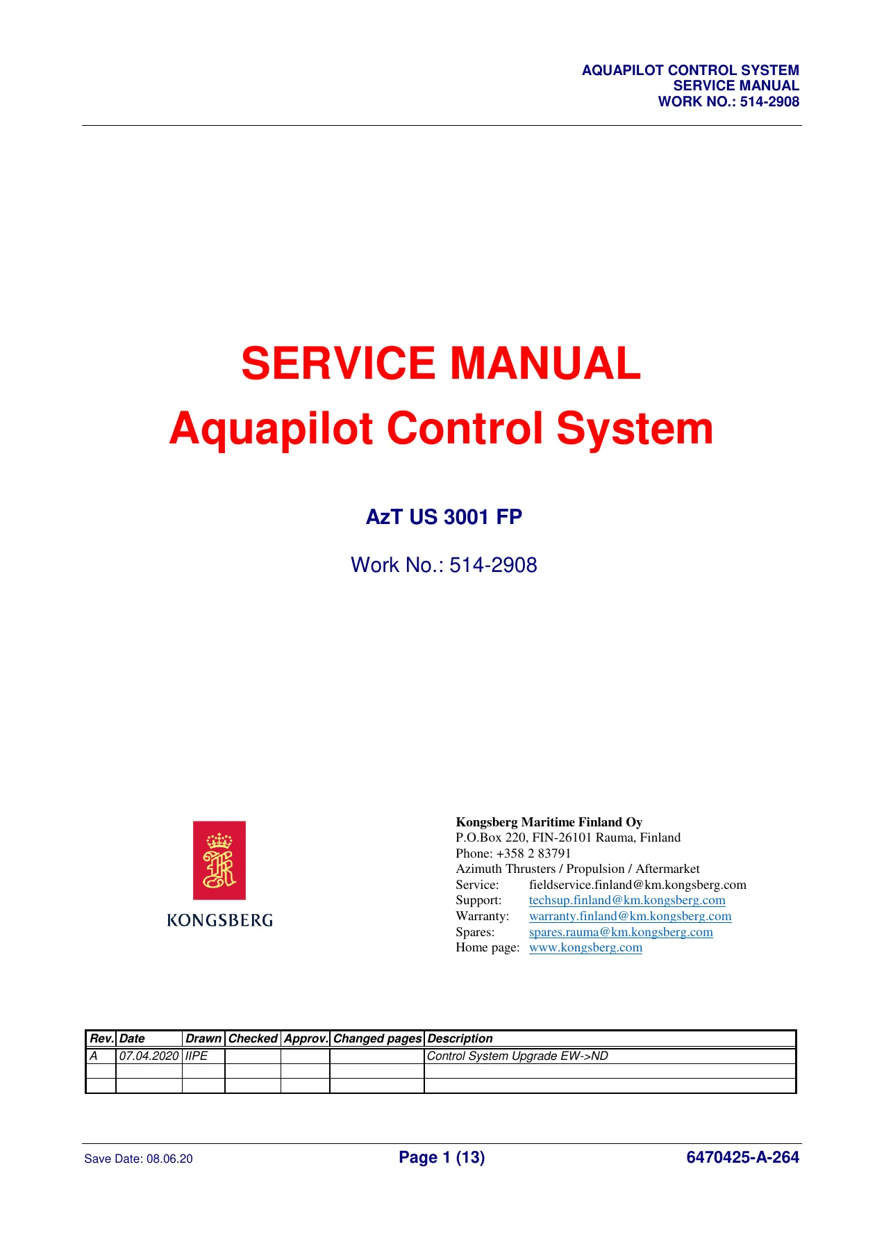
Kongsberg Aquapilot AzT US 3001 FP Control System Service Manual – 514-2908
Original price was: $39.95.$21.95Current price is: $21.95.
Comprehensive Kongsberg Aquapilot AzT US 3001 FP Control System Service Manual, Work No. 514-2908. Covers azimuth thruster control, steering, propulsion, maintenance, alarms, CANMAN processes, wiring diagrams and spare parts for US, UL, UUC, ULE and Contaz thruster units.
Description
Kongsberg Aquapilot AzT US 3001 FP Control System Service Manual
This is the complete Service Manual for the Kongsberg Aquapilot Control System as fitted to the AzT US 3001 FP azimuth thruster, published under Work No. 514-2908. It is the bench-level documentation used by service engineers to install, tune, maintain, diagnose and repair the Aquapilot control system, its azimuth thruster control units (ACU), bridge interface units (BIU), control panels, levers, indicators and hydraulic steering instrumentation. The document runs to 300 pages and spans everything from high-level system descriptions to component-level process block diagrams, wiring schematics, alarm point lists and spare-parts breakdowns.
The manual is written in English and carries revisions dating from 2008 through to 2020, including the 2020 control system upgrade from EW to ND. Where the original pages carry the Rolls-Royce Oy Ab, Rauma, Finland header, the document has been maintained by Kongsberg Maritime Finland Oy. It applies to the wider azimuth thruster family (US, UL, UUC, ULE and Contaz) and to the Aquapilot systems fitted to fixed-pitch propeller (FPP) thrusters with MCD.
File Details
- Manual type: Service Manual
- Brand: Kongsberg Maritime / Rolls-Royce Oy Ab
- Product model: AzT US 3001 FP
- Work No.: 514-2908
- Language: English
- Page count: 300
- File format: PDF
- Document revisions visible: A 07.04.2020 (EW to ND upgrade), plus older revisions dated 2008-2015 in individual chapters
- Models covered: US, UL, UUC, ULE, Contaz azimuth thruster units
Chapters Covered
The manual is organised into numbered chapters, with chapter-specific sub-sections for the systems, panels, cabling and processes that make up the Aquapilot control system.
- General Information – contents, general rules, terminology, safety information, disposal, spare parts ordering, global support network
- Control System Data – general electrical specifications
- Maintenance, Check Lists – general maintenance instructions, control system maintenance programme, Aquapilot control lever maintenance
- Settings and Adjustings – Hand Held Terminal HHT, tuning instruction, AZT thrust angle feedback and zero angle setting
- Alarms and Trouble Shooting – list of alarm points, MCD alarm points, serial link I/O alarm indications, alarm point descriptions
- Aquapilot Control System Description – Aquapilot for AZT with FPP and MCD
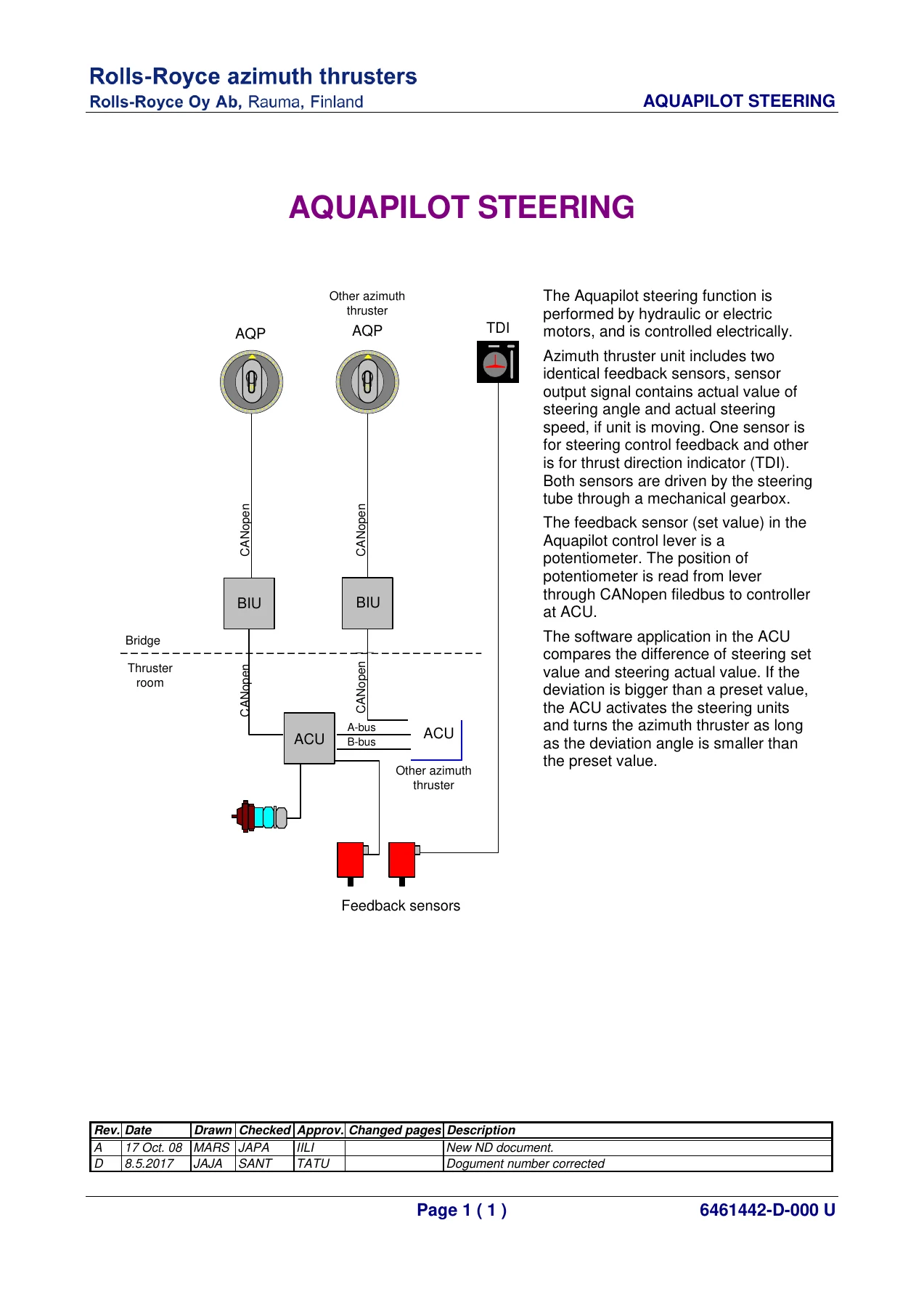
- Aquapilot Steering – steering control electronics, back-up / secondary steering system
- Secondary Steering – time-dependent back-up steering
- Propulsive Force Control – propeller RPM control, MCD clutch interface and speed control
- Maintenance Control System – maintenance control switch AMS08
- Thrust Direction and RPM Indication – thrust direction and speed indication, operation description, configuration switches
- CANMAN Processes – TURNCONT, THRUST, COMMAND, AQP2, SLIO, LT_D_5, SPECIAL, LOGICS, SUPERVIS (ACU11 and ACU12), PANELS3, CS_MODE_4
- Azimuth Thruster Control Unit – ACU dimension, assembly and wiring
- AZT and Hydraulic Instrumentation – transmitter box X2 wiring, RPM sensor wiring, additional RPM sensor, instrument cables for X3, X8 and X108 boxes
- Control Voltage Power Supply – DC main supply, AC power supply and battery change-over
- General Arrangement and Dimension Drawings – control system overview, Aquapilot control head, TDI-1 and TDI-2, ACP and AMP panels, BCP, CANopen cables, CS connections X15-1 and X15-2
- Installation, Storage – electric installations, storage instructions, storing of Aquamaster propulsion unit, electric motors
- Interconnection Diagrams – cabling instructions, cable list, plug connector cables, bus cables, control cables (thruster room, autopilot, back-up), data cables, alarm cables, power cables
- Part Lists – ACU, panel nodes, thrust direction indicator, back-up control panel and bridge interface unit assemblies
Beyond the chapter list, the manual provides detailed process block diagrams for the ACU’s internal CANMAN software processes, including turn control (TURNCONT), thrust control (THRUST), command handling, Aquapilot ND input/output, serial link I/O (SLIO), lamp test and dimmer functions, alarm handling (SUPERVIS) and panel node outputs. These block diagrams map every signal and parameter used by the control system, making them a practical reference for commissioning, tuning and fault tracing.
What This Manual Gives the Technician
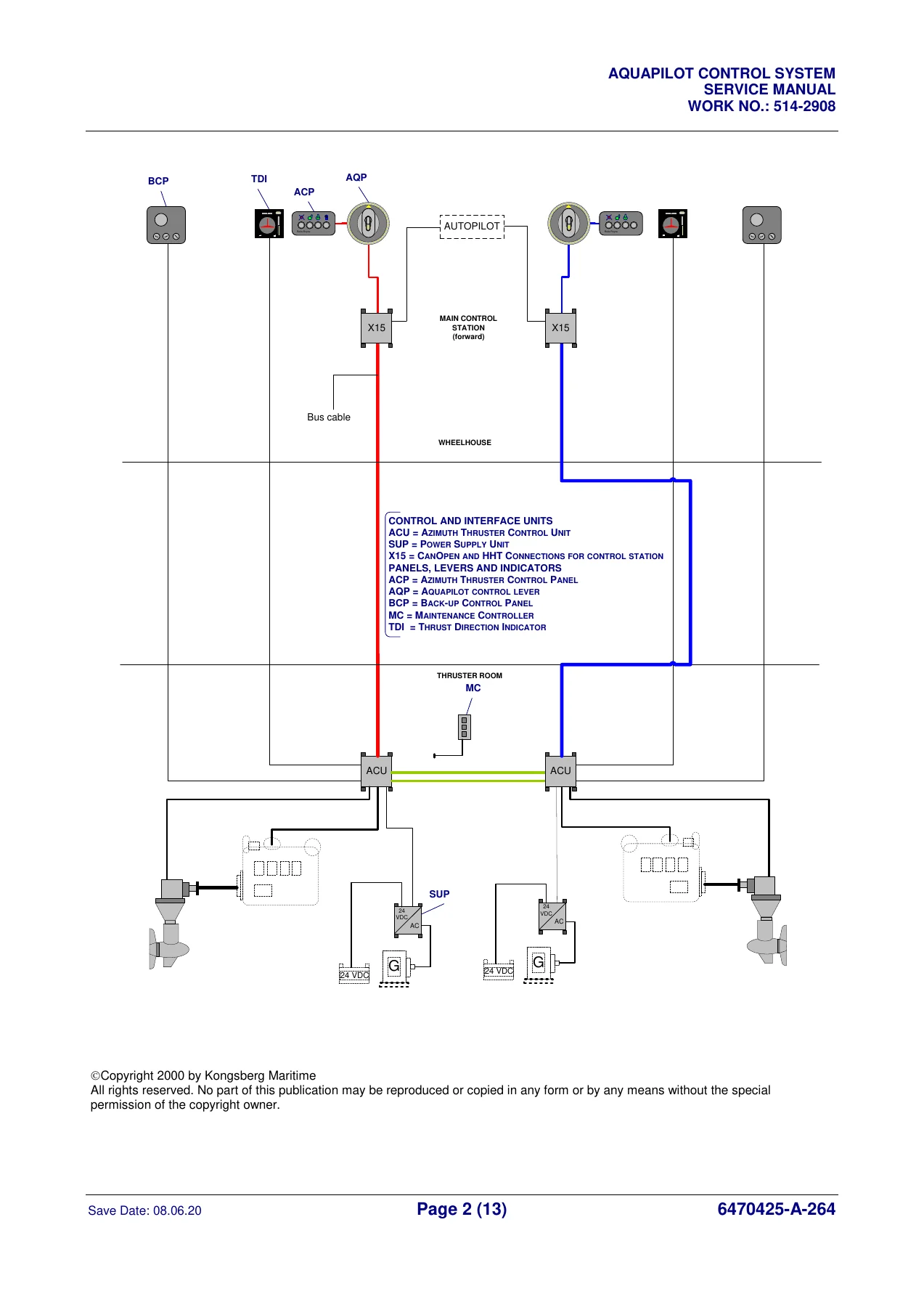
For anyone maintaining an Aquapilot-equipped vessel, this service manual is the single reference that connects the control lever on the bridge to the hydraulic steering gear and clutch on the azimuth thruster. It explains the follow-up (FU) steering principle, the non-follow-up (NFU) secondary steering system, the propeller RPM and MCD clutch control loop, and the CANopen / CAN bus architecture that ties the Aquapilot control head, bridge interface unit, thruster control unit and thrust direction indicator together.
The maintenance and check list chapters lay out inspection intervals from daily through to five-yearly, covering panel LED lamp tests, earth fault checks, alarm system tests, maintenance switch testing, transmitter checks, cable gland tightening and lamp bulb replacement. The alarm and troubleshooting chapter lists every alarm point with its monitoring area, sensor type, setting value, delay and remedy – essential when the ACU is flashing a warning and the vessel needs to get underway.
The tuning and settings chapters explain how to use the Hand Held Terminal (HHT) with the CCN02 controller: viewing and calibrating analogue and digital I/O, adjusting parameters, updating function curves and ramp tables, setting node IDs, bus bit rates and remote HHT connections. The Aquapilot lever calibration, dimmer tuning, steering control side selection and RPM reference value settings are all documented with the exact parameter names used in the software.
The wiring, cable list, cable flag code and interconnection diagram chapters give the shipyard or service engineer the information needed to trace, replace or extend the cabling between wheelhouse, thruster room and bridge interface unit, with each cable identified by its tag code (A-bus, B-bus, F-bus, data, alarm, power and control cables).
Azimuth Thruster Control Unit (ACU) Coverage
A substantial portion of the manual is dedicated to the Azimuth Thruster Control Unit itself. The ACU assembly drawings and wiring diagrams show the physical layout of the CCN02 marine controller, the SLIO-02 electronic unit, the I/U converters UG1 and UG3, the inverter UG4, surge and disturbance filters, relay modules and the terminal arrangement inside the 600 x 1000 x 250 mm IP44 enclosure. The part lists break the ACU down to individual items – circuit breakers, cable glands, terminal blocks, earth bars, CAN connectors, relay modules and the SCR-3S secondary steering electronic unit – with Kongsberg part numbers for ordering.
Panels, Indicators and Spare Parts
The manual covers the full control station set: Aquapilot (AQP) control head, Thrust Direction Indicator (TDI-11 / TDI-12), Azimuth thruster Control Panel (ACP), Azimuth thruster Mode Panel (AMP) and Back-up Control Panel (BCP). Each panel is documented with its wiring, dimensions, configuration switches, bus IDs and part list. The TDI chapter explains the digital encoder interface, RPM scaling switches S1-S7, configuration switch SW1, error codes E01 and E02, dimmer control and the bar display proportional to propeller thrust. The part lists at the back provide the complete bill of materials for the ACU, panel nodes, TDI, BCP and BIU, with Kongsberg RRM part numbers.
Why This Manual Matters
Azimuth thruster control systems are safety-critical: incorrect steering calibration, a mis-set RPM reference or a wrong clutch parameter can lead to loss of manoeuvrability in confined waters. The Kongsberg Aquapilot AzT US 3001 FP service manual gives the exact parameters, function curve tables, calibration procedures and alarm thresholds needed to keep the system within specification. It is also the reference for the Hand Held Terminal session work that authorised service personnel use to diagnose and reconfigure the CCN02 controller – the manual explicitly warns that parameter changes beyond viewing are work for authorised service personnel only, and that unauthorised changes void warranty and may create operational hazards.
IMAGES PREVIEW
Instant PDF Delivery
This listing is for the PDF version of the manual. Once payment is complete the file is available for immediate download – no shipping, no waiting for a physical book. The PDF can be viewed on any laptop, tablet or smartphone, printed for the workshop or engine room, and kept on board as a searchable reference for the vessel’s service history. Whether you are commissioning a new Aquapilot system, tuning a replacement ACU, tracing an alarm, ordering spares or planning a five-year maintenance window, this service manual is the document that tells you how the system is built and how it is meant to be set up.
Reviews
There are no reviews yet.