
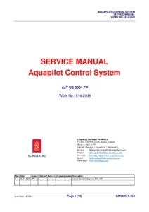
Kongsberg Aquapilot Control System Service Manual – AzT US205 FP Azimuth Thruster
Original price was: $39.95.$23.95Current price is: $23.95.
Complete Kongsberg Aquapilot Control System service manual for the AzT US205 FP azimuth thruster (Work No. 514-U371, serials U371A/U371B). Covers steering, secondary steering, propeller RPM control, CANMAN processes, ACU tuning, alarms, cabling and interconnection diagrams.
Description
Kongsberg Aquapilot Control System Service Manual – AzT US205 FP
This is the service manual for the Kongsberg Maritime Aquapilot Control System fitted to the AzT US 205 FP azimuth thruster, issued under Work No. 514-U371 and covering serial numbers U371A and U371B. It is the reference document used by service engineers and trained crew for maintaining, adjusting, tuning and troubleshooting the complete Aquapilot control chain, from the bridge control lever and panels down to the azimuth thruster control unit, the hydraulic instrumentation and the fieldbus network.
The manual is written in English and is built around the Kongsberg Maritime Finland Oy documentation set for the US, UL, UUC, ULE and Contaz azimuth thruster families, with the AzT US 205 FP as the applied configuration. It is a working document: procedures are given in numbered steps, values are stated as calibration points and parameter names, and the electrical, bus and Ethernet connections are referenced to the corresponding Kongsberg drawing numbers so each task can be traced back to the correct schematic.
File Details
- Manual type: Service Manual
- Brand: Kongsberg Maritime (Kongsberg Maritime Finland Oy)
- Technical name: Control System
- Product: Aquapilot Control System
- Applied model: AzT US 205 FP azimuth thruster
- Work / project number: 514-U371
- Serial numbers: U371A, U371B
- Language: English
- File format: PDF
- Revision: A (7.3.2023, new document)
Chapters Covered
- General Information – contents of the Aquapilot service manual, general rules, terminology, warnings and cautions guidance, safety information, product disposal and scrapping, ordering spare parts, global support network
- Control System Data – general electrical specifications
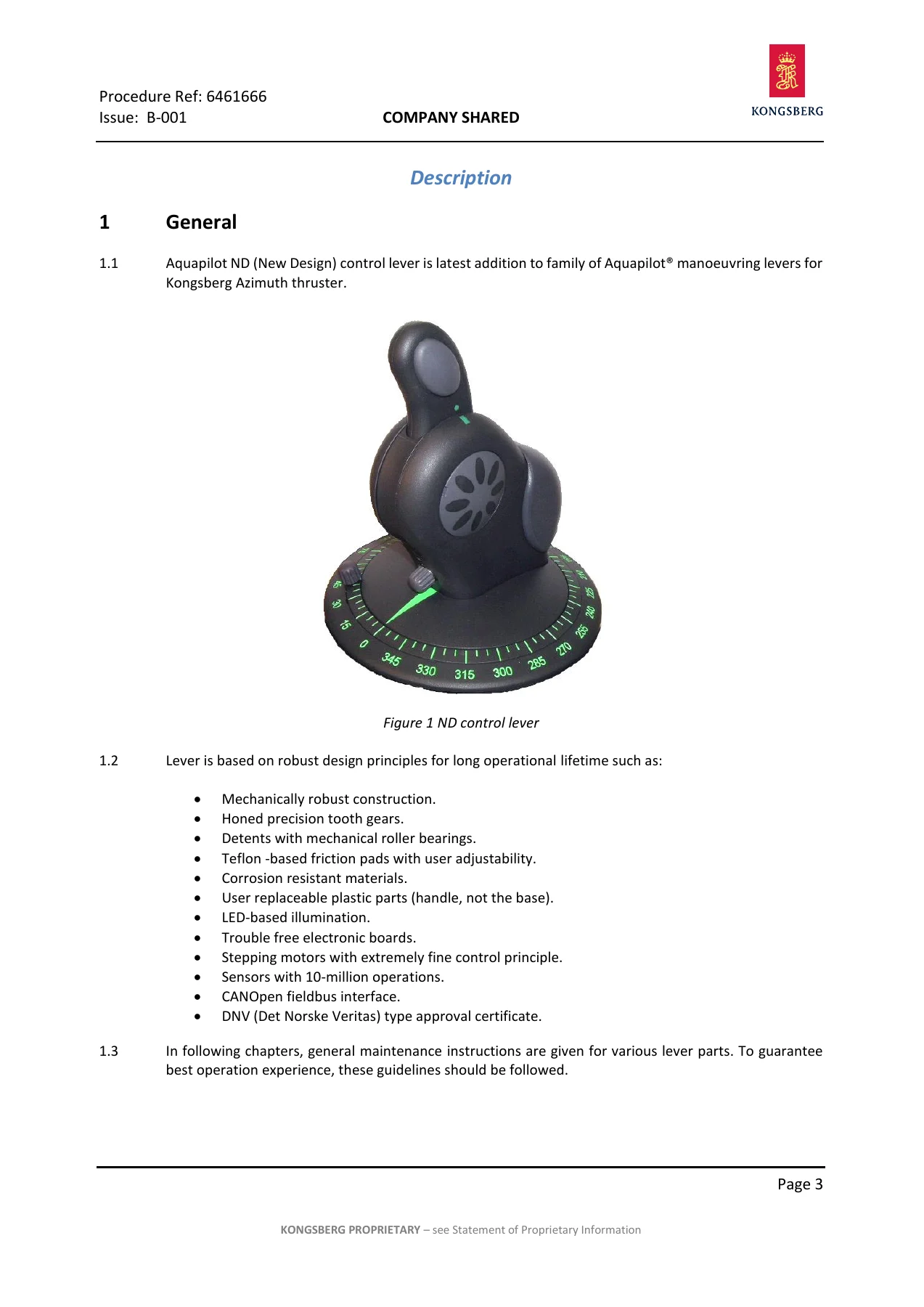
- Maintenance, Check Lists – general maintenance instructions, maintenance programme for the control system and for the Aquapilot control lever
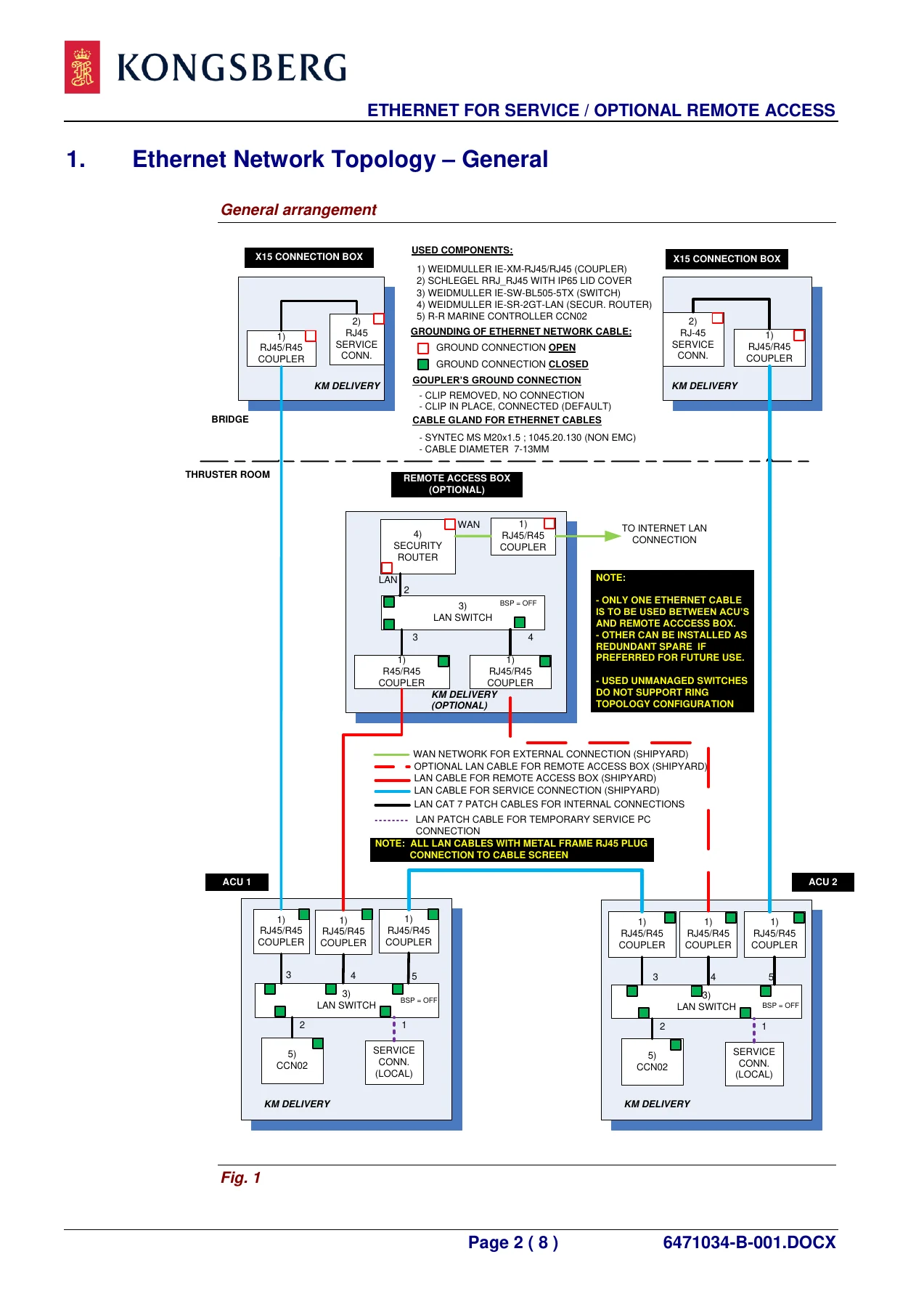
- Settings and Adjustings – HHT terminal software user’s guide, Ethernet for service and optional remote access, tuning instruction, TDI-XDi tuning instruction, XDi indicators data sheet and installation guide, AZT thrust angle feedback and zero angle setting, rotary encoder with CANopen interface, operation description of slipping clutch
- Alarms and Trouble Shooting – list of alarm points, serial link I/O units alarm indications, descriptions of alarm points
- Aquapilot Control System Description – Aquapilot for AZT with FPP and slipping clutch
- Aquapilot Steering – steering function in the CANopen-based ND system
- Secondary Steering – time-dependent back-up steering control
- Propeller RPM Control – propeller RPM control with slipping clutch
- Maintenance Control System – maintenance control switch AMS08
- CANMAN Processes – TURNCONT, THRUST, CLUTCH, COMMAND, AQP1, SLIO, LT_D_5, AUPI, OVERRIDE, LOGICS, ALARMS, SUPERVIS (ACU11 and ACU12), PANELS1, VDR, FIFI
- Azimuth Thruster Control Unit – ACU dimensions, ACU3789.002 assembly and wiring
- AZT and Hydraulic Instrumentation – transmitter box X2 wiring, instrument cables for X3, X9, X8 and X108 boxes
- Control Voltage Power Supply – 24 VDC uninterrupted supply
- Interface to Other Control Systems – azimuth thruster interface to autopilot
- General Arrangement and Dimension Drawings – control system overview, Aquapilot control head for FPP, TDI-XDi indicators and dimmer unit, slipping clutch panel ASP, back-up control panel BCP, CANopen cables, connection boxes X3, X9, X8 and X108
- Installation, Storage – electric installations, storage instructions, storing of the azimuth thruster propulsion unit, electric motors
- Interconnection Diagrams – cabling instructions, cable list, bus cables, back-up control cables, autopilot cables, indicator and data cables, engine room cables, alarm cables, power cables, bridge control power supply, plug connector cables and Ethernet connections
- Part Lists
Taken as a whole, this Kongsberg Aquapilot Control System service manual gives a technician the full maintenance logic of the installation rather than a single repair procedure. The early chapters set the electrical and environmental ground rules for the control system; the middle chapters explain how the Aquapilot lever, the azimuth thruster control unit and the slipping clutch actually work together, including the follow-up steering loop, the non-follow-up secondary steering back-up and the split between clutch slipping and prime mover speed control; the later chapters provide the tuning tables, parameter names and calibration points needed to bring a system back into specification, and the drawing and cable lists needed to trace a fault through the cabinets. The CANMAN process listings are particularly useful because they map application processes such as TURNCONT, THRUST, CLUTCH, AUPI and ALARMS to the signals and parameters that a service engineer inspects through the HHT terminal software.
What This Manual Lets You Do
With this document on hand you can carry out scheduled maintenance on the Aquapilot control system and the Aquapilot ND control lever, test panel LEDs and alarm units, check earth faults and cable connections, and work through the defined maintenance programme for the control system at its 6-month, 1-year and 5-year intervals. You can tune the installation using the Aquapilot tuning tables – the unlinearity correction table L1-COR-T, the RPM request table AQP-RPM-T, the clutch and prime mover parameters such as AQP-SC-MIN, AQP-SC-MAX, AQP-PM-MIN and AQP-PM-MAX, the dimmer adjustment table D1-COR-T, and the turning speed tables PWM-CW MIN/MAX used for the remote steering control loop.
You can also set the steering feedback correctly, which is one of the most common sources of azimuth angle error: the manual walks through mechanical zero positioning of the thruster, the 0-direction setting of the steering transmitter sensor B3 and the indicator transmitter sensor B4 on the terminal strip of transmitter box X2, including the exact terminals and the 5-second zeroing window. On the electrical side, the cabling instruction chapter and cable list give the conductor sizes, impedance requirements, gland sizes, shield termination rules, minimum separation distances between power and signal cables, and the 24 VDC voltage drop calculation used for control voltage supply distribution.
Why the Correct Procedures and Values Matter
The Aquapilot system is a digital follow-up steering system with a hardwired secondary back-up, and its behaviour depends on calibration values that are not obvious from the outside. An azimuth feedback sensor that has not been zeroed at the true mechanical zero position, a slipping clutch curve set outside its normal band, or a turning speed table filled in with the wrong PWM values will all produce a thruster that appears to function but does not follow the lever command correctly – exactly the kind of fault that is difficult to diagnose without the parameter and calibration references. Equally, the manual stresses safety practice throughout: switching on the maintenance switch before working on the control unit, de-energizing the correct supplies, checking that the system cannot be operated remotely while local transmitter calibration is being carried out, and treating back-up control as a manoeuvring aid for reaching a safe location rather than a normal operating mode.
IMAGES PREVIEW
Instant PDF Delivery
The Kongsberg Aquapilot Control System service manual for the AzT US 205 FP is delivered as an instant PDF download, with no shipping and no waiting for a physical copy. It opens on any laptop, tablet or phone, can be printed page by page for use in the thruster room, and can be kept on the vessel or in the workshop as a permanent service reference for the AzT US 205 FP installation under Work No. 514-U371.
Reviews
There are no reviews yet.