
Kubota M8540 M9540 Tractor Workshop Manual 2006 PDF Service Repair
Original price was: $39.95.$23.95Current price is: $23.95.
Complete 662-page Kubota factory workshop manual for M8540 and M9540 tractors (2WD & 4WD, ROPS & CABIN). Covers engine, clutch, transmission, hydraulics, electrical, brakes, front axle, steering and cabin air conditioning.
Description
Kubota M8540 M9540 Tractor Workshop Manual
This is the complete Kubota workshop manual for the M8540 and M9540 tractors, published in April 2006. At 662 pages it is the full dealer-level service document covering every major system on these machines, from the V3 series diesel engine through to the cabin air conditioning unit. Whether you are servicing your own tractor, running a repair shop, or maintaining a fleet, this manual gives you the procedures, specifications and exploded views needed to do the job correctly.
The manual covers both 2WD and 4WD variants of the M8540 and M9540, in both ROPS and CABIN configurations. It is divided into three logical parts as Kubota intended: General (identification, precautions, maintenance schedules, special tools), Mechanism (how each system is constructed and how it functions), and Servicing (troubleshooting, specifications, torque values, disassembly, assembly and adjustment).
File Details
- Manual type: Workshop Manual (WSM)
- Brand: Kubota
- Models covered: M8540, M9540 (2WD and 4WD)
- Language: English
- Page count: 662 pages
- File format: PDF
- Publication date: April 2006
- Engine family: V3 series DI diesel (V3800DI-TE3)
Chapters Covered
- General (G) – Tractor identification, model name and serial numbers, engine serial number, E3 engine identification, cylinder numbering, general precautions, handling precautions for electrical parts and wiring, lubricants, fuel and coolant, tightening torques, maintenance schedule, check and maintenance points (daily through 3000 hours / 2 years), special tools, tires, implement limitations
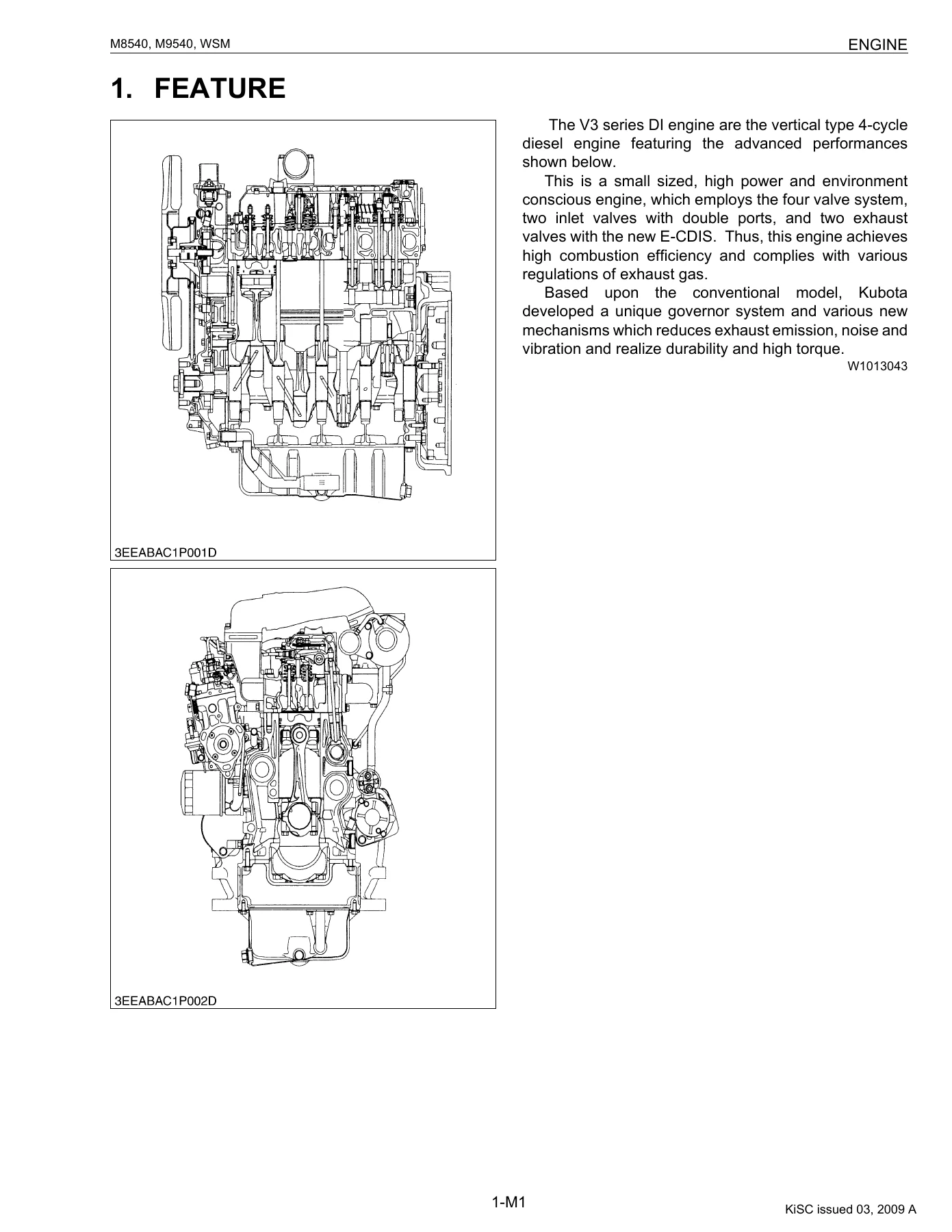
- Engine (1) – Features, cylinder block, half-floating head cover, cylinder head, Center Direct Injection System (E-CDIS), piston, built-in dynamic balancer, oil cooler, thermostat, bottom bypass system, governor, 2 stage DI nozzle, injection pump with F.S.P., mechanical timer with cold start advance, intake air heater, Exhaust Gas Recirculation (EGR) system
- Clutch (2) – Traveling clutch (hydraulic shuttle and synchro shuttle models), PTO clutch, structure and oil flow, PTO clutch valve
- Transmission (3) – Structure for hydraulic shuttle and synchro shuttle models, power train for traveling gear, shuttle shift section, hydraulic shuttle valve, main gear shift section, Hi-Lo shift section, shift fork rod and fork, four wheel drive section, lubrication, PTO gear section
- Rear Axle (4) – Features and final drive mechanism
- Brakes (5) – Traveling brake structure, master cylinder assembly, parking brake structure, restriction device (parking brake lever and main gear shift lever)
- Front Axle (6) – 2WD structure, 4WD structure, Limited Slip Differential (LSD)
- Steering (7) – Full hydrostatic power steering, steering mechanism, steering cylinder
- Hydraulic System (8) – Structure, hydraulic circuit (hydraulic shuttle and synchro shuttle), oil cooler relief valve, three-point hydraulic system, hydraulic block, linkage mechanism (position control, draft control, mixed control), hydraulic cylinder
- Electrical System (9) – Wiring diagrams (main harness for ROPS and CABIN, cabin harness, engine harness), electrical circuit detailed chart, instrument panel board, starting system, instrument panel (LCD monitor), OPC (Operator Presence Control), lighting system, trailer socket
- Cabin (10) – Air conditioning system structure, compressor, air conditioner unit, system control, air flow, air control vent, electrical system, refrigerant cycle servicing and repair
What This Workshop Manual Gives You
This is a genuine Kubota workshop manual, written for service personnel. It is not a generic repair guide or a reprint. Every procedure is specific to the M8540 and M9540 platform, with factory specifications, allowable limits, tightening torques and step-by-step disassembly and reassembly instructions for each system. The General section alone includes the complete maintenance schedule with intervals from the initial 50-hour service through to the 2-year items, along with a full lubricants and capacities chart.
The Mechanism section explains how each system is built and how it operates before you start troubleshooting. The Servicing section then provides the troubleshooting tables, servicing specifications with factory values and allowable limits, and detailed checking, disassembling and servicing procedures. This three-part structure is exactly what makes a Kubota workshop manual so useful: you understand the system first, then you diagnose and repair it correctly.
Systems and Procedures Covered
- Engine: Compression pressure testing, valve clearance adjustment, cylinder head disassembly, thermostat testing, injection pump unit removal and installation (E2 and E3 engine variants), water pump and oil cooler, gear case, piston and connecting rod, flywheel and crankshaft, servicing specs for cylinder head, idle gear and camshaft, piston and connecting rod, crankshaft, cylinder and oil pump
- Clutch: Clutch pedal free travel adjustment for ROPS and CABIN models, PTO clutch lever stroke and relief valve setting pressure, clutch pedal removal, damper disc, clutch assembly, release holder and release lever, PTO clutch valve and PTO clutch pack disassembly and servicing
- Transmission: Shuttle lever adjustment, main gear shifting checks, shuttle valve system pressure checks, hydraulic shuttle valve removal, separating the transmission from the clutch housing, shuttle section disassembly, shift cover, clutch housing internals, transmission case internals including hydraulic pump holder, PTO section and differential gear
- Rear Axle: Separating the rear axle on ROPS and CABIN models, brake section, planetary gear, rear axle shaft and bearings
- Brakes: Brake pedal free travel and stroke adjustment, equalizer working level, bleeding the brake system, parking brake lever adjustment, restriction lever adjustment, master cylinder removal and disassembly, brake piston, brake disc and plate, parking brake gear
- Front Axle: Toe-in adjustment, axial sway check, front axle pivot adjustment, bevel gear case and stopper adjustment, separating front axle on 2WD and 4WD, disassembling the front axle, differential gear (LSD) removal and disassembly, servicing of knuckle shafts, bushings, bevel gears, planetary gears and LSD slip torque
- Steering: Relief valve setting pressure, steering controller removal and disassembly, steering cylinder removal and disassembly for 2WD and 4WD, servicing of steering cylinder I.D. and rod-to-bushing clearance
- Hydraulic System: Hydraulic flow test, relief and safety valve setting pressure, position and draft control linkage adjustment, auxiliary control valve linkage adjustment, oil cooler relief valve, hydraulic pump disassembly, top cover removal, hydraulic linkage, control valve, hydraulic cylinder, relief valve, safety valve, top link bracket, lift arm and lift arm shaft, lowering speed adjusting valve
- Electrical System: Battery, fuse, grounding and connector checks, main switch testing (ROPS and CABIN), air heater, starter motor, engine stop solenoid, alternator, meter panel setting mode and checking mode, lighting switches and flasher unit, relays, OPC system, starter motor and alternator disassembly and servicing
- Cabin: Air conditioning troubleshooting, servicing specifications, refrigerant cycle precautions, handling service tools, checking with manifold gauge, discharging, evacuating and charging, compressor, relays, control panel, blower resistor, blower motor, temperature motor, mode motor, recirculation/fresh air motor, pressure switch, wiper switches and motors, separating the cabin from the tractor, removing the compressor, air conditioner unit, air conditioner pipes, heater hoses, cab windshield and wiper motor
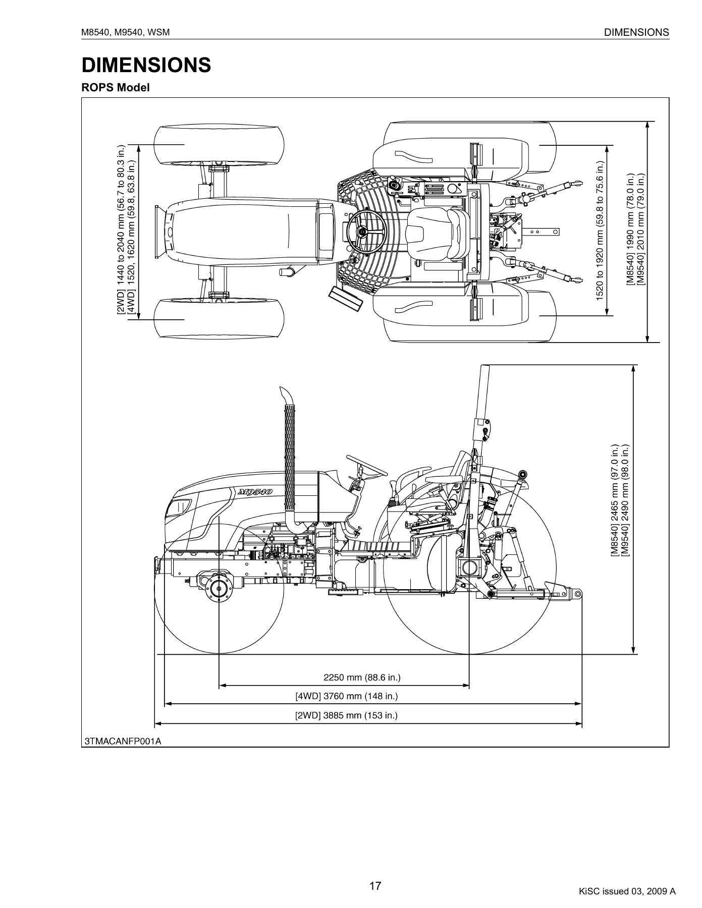
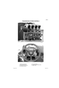
IMAGES PREVIEW
Who This Manual Is For
This Kubota M8540 M9540 workshop manual is written for anyone who needs to service, repair or rebuild these tractors to factory standard. That includes:
- Owners who do their own maintenance and repairs
- Independent repair shops working on Kubota tractors
- Agricultural mechanics and technicians
- Fleet maintenance operations
- Anyone preparing a tractor for resale or restoring a used machine
The level of detail is genuine workshop-manual detail. Torque values, clearances, wear limits, adjustment procedures and exploded diagrams are all included. If you are doing a clutch replacement, an engine rebuild, a hydraulic repair or chasing an electrical fault, this manual tells you how the system is supposed to work and exactly how to test, disassemble, repair and reassemble it.
Why a Proper Workshop Manual Matters
Working on a modern tractor without the correct specifications is how expensive mistakes happen. A clutch pack assembled with the wrong clearance will drag or slip. A hydraulic relief valve set too low will cause weak lift performance. An engine rebuilt with the wrong piston protrusion will have poor compression or worse. This manual removes the guesswork by giving you the numbers Kubota’s own service technicians use.
The M8540 and M9540 are capable, durable tractors, and with the right information they are very serviceable machines. This workshop manual is the single most useful document you can have if you plan to keep one running properly for years to come.
Instant PDF Delivery
This Kubota M8540 M9540 workshop manual is delivered as an instant PDF download. There is nothing to wait for and nothing to ship. Once your order is complete you can download the file immediately and open it on any device: laptop, desktop, tablet or smartphone. The pages can be printed if you prefer a paper copy for the workshop, and you can print just the sections you need for a particular job. Keep it on a USB stick, a shop computer, or your phone for quick reference while you are working on the tractor.
With 662 pages covering every major system on the M8540 and M9540, this is the complete reference for maintaining and repairing these tractors to factory standard.
Reviews
There are no reviews yet.