Description
Kubota SSV65 Hand and Foot Controls Workshop Manual 2018
This Kubota SSV65 Hand and Foot Controls Workshop Manual 2018 is the machine-level workshop manual (WSM) for the SSV65 skid steer loader built with hand and foot controls. It is written for technicians who need safety rules, identification data, capacities, maintenance intervals, body and hitch work, hydraulic circuit and performance checks, electrical diagnosis, and cabin air-conditioning service on one model family. Open-cab and closed-cab machines are both treated, including separate fuse and relay maps. Hydraulic circuit pages are split by machine serial number, and fuel-hose routing is split by a later serial break.
The document title page identifies it as a Workshop Manual for Skid Steer Loader SSV65 Hand and Foot Controls, issued KISC 03, 2018 A. The reader pages date the first issue May 2015, with a recorded revision through March 2018 that corrected the hydraulic circuit, front speed, lift-arm and bucket cylinder drift values, high-flow pump (P2) flow volume, fuel-hose routing, and lubricant, fuel and coolant volumes.
File Details
- Manual type: Workshop Manual (WSM)
- Brand / model: Kubota SSV65 skid steer loader, hand and foot controls
- Cab types: Open Cab and Closed Cab
- Language: English
- Page count: 544
- File format: PDF
- Issue mark: KISC issued 03, 2018 A
- First issue / latest recorded revision: May 2015 / March 2018 (revision 4)
Machine Covered by This SSV65 Workshop Manual
Main specifications list the SSV65 as a water-cooled four-cycle four-cylinder diesel with EPA Tier 4 aftertreatment. The engine model printed in the information tables is V2607-CR-TE4; the engine chapter nameplate specification is V2607-CR-TE4-SL1-Q. Operating weight including the operator is 3080 kg (6790 lbs) for the open cab and 3200 kg (7055 lbs) for the closed cab. Rated operating capacity is 885 kg (1950 lbs) with a tipping load of 1770 kg (3900 lbs). Bucket breakout force is 2195 kg (4839 lbs) and lift-arm breakout force is 1750 kg (3858 lbs).
Travel is given as 17.8 km/h (11.1 mph) fast and 11.1 km/h (6.9 mph) slow in the main specification table. Attachment hydraulics are listed at 68 L/min (18.0 US gal/min) standard flow and 106 L/min (28.0 US gal/min) high-flow, with a maximum pressure of 22.5 MPa (230 kgf/cm²) (3271 psi). Fuel tank capacity is 96 L (25.4 US gal). The machine battery in the same table is 12 V, RC 160 min, CCA 900 A.
The engine specification sheet adds bore and stroke 87 × 110 mm, displacement 2615 cm³, compression ratio 16.8, firing order 1-3-4-2, external EGR, Denso common-rail injection, counterclockwise rotation from the flywheel, rated output 47.0 kW / 2800 min⁻¹ net (ISO 8178) and 47.7 kW / 2800 min⁻¹ gross (SAE J1995), and maximum torque 221.6 N·m / 1500 min⁻¹ net. Compression pressure is 3.2 MPa with an allowable limit of 2.2 MPa. The engine chapter also prints an alternator of 12 V (960 W), a starter of 12 V (2 kW), and a 12 V (100 Ah) battery figure on that sheet.
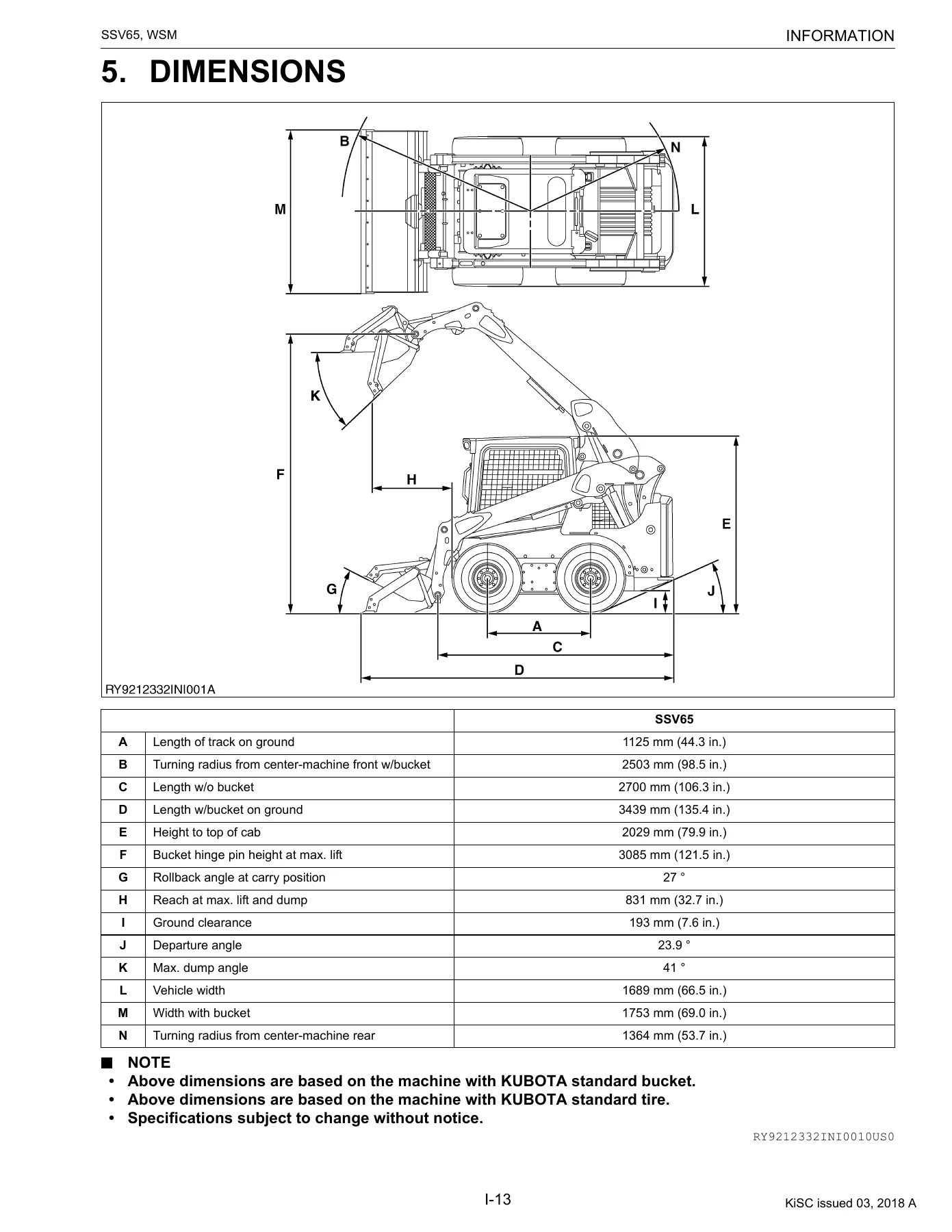
Dimensional data for the loader with the Kubota standard bucket and standard tire include length with bucket on the ground 3439 mm (135.4 in.), height to top of cab 2029 mm (79.9 in.), bucket hinge-pin height at max lift 3085 mm (121.5 in.), reach at max lift and dump 831 mm (32.7 in.), ground clearance 193 mm (7.6 in.), vehicle width 1689 mm (66.5 in.), and width with bucket 1753 mm (69.0 in.).
Chapters Covered
- To the Reader — how service specifications and service limits are defined; related engine WSM, diagnosis manual, and DPF handling manual references for V2607-CR-TE4
- I Information — Safety First; Safety Precautions for Work (before working / when working); Safety Decals (locations and care of labels); Main Specifications; Dimensions
- G General — Engine Identification (model name and serial number, E4B engine notes, cylinder number); Muffler Full Assembly Identification; General Precautions; Handling Precautions for Electrical Parts and Wiring; Tightening Torques; Lubricants, Fuel and Coolant; Maintenance (intervals, other adjustments and replacements including fuses)
- 1 Engine — Specifications; Dimensions; Performance Curve; Servicing (radiator removal and installation; DPF muffler removal and installation; engine removal and installation; fuel hose routing)
- 2 Machine Body — Front (cab tilt, lift arm stopper, jack up, lift arm / link / control link, vacuum pump, mechanical quick hitch, hydraulic quick hitch option, front pins and bushes); Upper Structure (ROPS cabin, windshield, seat bar, seat and seatbelt); Lower Chassis Layout (fuel tank, rear hood, hydraulic oil tank, axle shaft, sprocket)
- 3 Hydraulic System — Hydraulic circuit diagrams serial no. TO 13705 and FROM 13706 (mechanical and hydraulic hitch combinations with high-flow, self-leveling valve, and ride control); Hydraulic Equipment Layout; Hydraulic System mechanism (front operation and travel system); Service Data; Performance Checks and Adjustment Methods; Hydraulic Equipment; Routing of Hydraulic Hoses
- 4 Electrical System — Diagnosing Malfunctions; Wiring Circuit; Electronic Equipment Layout; Electrical Connector Layout; Terminal Names of the Main Connector; Instrument Panel (user mode and service mode); Troubleshooting by error code; Flow Chart of the User Mode and Service Mode Settings
- 5 Cabin — Air Conditioning System mechanism; Wiper; Troubleshooting; Maintenance and service-related specifications; Precautions when repairing the refrigerant system; Inspecting and charging the refrigerant system; Inspection and disassembly
Taken together, the Kubota SSV65 Hand and Foot Controls Workshop Manual 2018 is a chassis, hydraulics, electrics, and cabin service book. Engine pages in this file concentrate on identification, installed-engine specifications and performance curves, radiator and DPF muffler R&I, pulling the engine from the frame, and fuel-hose layouts. Internal engine rebuild, CRS diagnosis, and DPF handling are pointed to the separate V2607-CR engine workshop, diagnosis, and DPF handling manuals named in the reader section.
Fluids, Intervals, and Shop Practice
Lubricant, fuel and coolant capacities printed for the SSV65 include engine oil 7.5 L (1.98 U.S. gals) API CJ-4 including the filter; coolant 8.8 L (2.3 U.S. gals) LLC-N-50F at a 50 percent mix including the reserve tank; fuel 96 L; hydraulic oil tank 11.2 L and hydraulic system 35 L of Kubota Hydraulic Fluid 46HD; chain case 20.5 L of the same fluid each side; EP2 grease; and air-conditioning refrigerant 850 to 950 g (1.9 to 2.1 lbs). Hydraulic level checks are specified with the machine on flat ground, lift arm fully down, attachment fully rolled back, and oil at 20 to 30 °C (68 to 86 °F).
The interval chart runs from daily and 10-hour checks through 50, 250, 500, 1000, 1500, 2000 and 3000 hour items, plus calendar work at one and two years. Typical tasks include engine and hydraulic oil, filters, drive-chain tank oil, air cleaner inner and outer elements, V-belt tension, wheel-bolt torque, tire pressure, foot-pedal greasing, radiator and oil cooler, water separator, DPF cleaning at 3000 hours, and emission-related inspections flagged for dealer service. Closed-cab air-conditioner filters, drains, condenser, pipes and refrigerant have their own schedule. Fuel must be ultra-low sulfur diesel below 0.0015 percent (15 ppm) with API CJ-4 oil; the manual warns that other fuel or oil can shorten the 3000-hour DPF cleaning interval.
General shop pages cover plumber’s tape on taper fittings, O-ring and oil-seal orientation, floating seals, snap rings, spring pins, thread adhesive, bolt tightening patterns, hydraulic hose and ORS face-seal assembly, quick couplings, and electrical rules (negative battery cable first, no rewiring, fuse replacement with the same rating). Open-cab and closed-cab fuse and relay lists are printed separately. Closed-cab extras include compressor, blower motor, wiper and A/C switch circuits. Auxiliary outlet power is limited to less than 120 W.
Hydraulics, Serial Splits, and Performance Checks
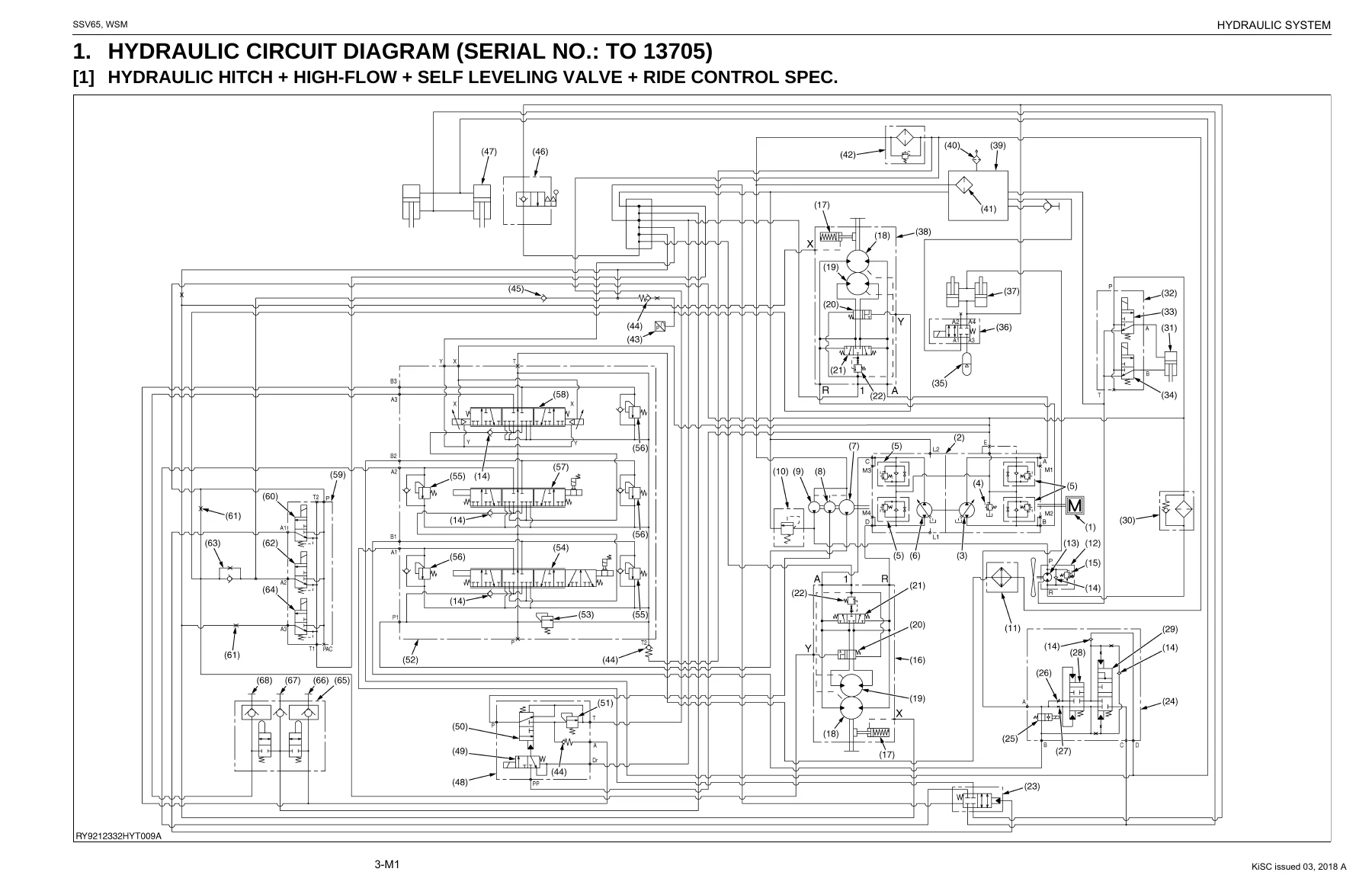
Hydraulic circuit diagrams are drawn twice: serial no. TO 13705 and serial no. FROM 13706. Each block covers mechanical quick hitch and hydraulic hitch machines, with and without high-flow, self-leveling valve, and ride control. Mechanism text then walks oil flow for lift-arm raise, float, bucket dump, self-level, single-flow AUX, high-flow AUX, ride control, hydraulic hitch lock, forward travel, spin turn, charge and flushing circuits, two-speed travel, and the parking brake.
Complete PDF Bookmark Tree
Complete Bookmarks
The complete bookmarks in the “Kubota SSV65 Hand and Foot Controls Workshop Manual 2018 – Skid Steer Loader WSM PDF” are as follows:
+SSV65 HAND AND FOOT CONTROLSp. 1
TO THE READERp. 2
CONTENTSp. 4
+I INFORMATIONp. 5
+INFORMATIONp. 6
1. SAFETY FIRSTp. 7
+2. SAFETY PRECAUTIONS FOR WORKp. 8
[1] PRECAUTIONS BEFORE WORKINGp. 8
[2] PRECAUTIONS WHEN WORKINGp. 9
+3. SAFETY DECALSp. 14
[1] LOCATIONSp. 14
[2] CARE OF LABELSp. 17
4. MAIN SPECIFICATIONSp. 18
5. DIMENSIONSp. 19
+G GENERALp. 20
+GENERALp. 21
+1. ENGINE INDENTIFICATIONp. 22
[1] MODEL NAME AND SERIAL NUMBERp. 22
[2] E4B ENGINEp. 24
[3] CYLINDER NUMBERp. 24
+2. MUFFLER FULL ASSEMBLY IDENTIFICATIONp. 25
[1] PART NUMBER AND SERIAL NUMBERp. 25
3. GENERAL PRECAUTIONSp. 27
+4. HANDLING PRECAUTIONS FOR ELECTRICAL PARTS AND WIRINGp. 31
[1] WIRINGp. 31
[2] FUSESp. 35
[3] CONNECTORp. 35
[4] WASHING THE MACHINE WITH A HIGH-PRESSURE WASHERp. 37
+5. TIGHTENING TORQUESp. 38
[1] GENERAL USE SCREWS, BOLTS AND NUTSp. 38
[2] STUD BOLTSp. 38
+[3] TORQUE FOR HYDRAULIC HOSE FITTINGSp. 39
(1) Torque for Hydraulic Hose Fittingsp. 39
(2) Torques of Lock-Nuts for Elbows with Male Seats and Adapters with O-rings (Straight Threads)p. 40
(3) Torque for Tapering Adaptorsp. 40
[4] HOSE CLAMP SCREW TORQUEp. 41
6. LUBRICANTS, FUEL AND COOLANTp. 42
+7. MAINTENANCEp. 43
[1] MAINTENANCE INTERVALSp. 43
+[2] OTHER ADJUSTMENTS AND REPLACEMENTSp. 46
+1 ENGINEp. 50
+GENERALp. 51
1. SPECIFICATIONSp. 52
2. DIMENSIONSp. 53
3. PERFORMANCE CURVEp. 54
+SERVICINGp. 55
+1. ENGINEp. 56
+[1] RADIATORp. 56
(1) Removal and Installationp. 56
+[2] DPF MUFFLERp. 61
(1) Removal and Installationp. 61
+[3] ENGINEp. 66
(1) Removal and Installationp. 66
[4] FUEL HOSE ROUTINGp. 71
+2 MACHINE BODYp. 73
+SERVICINGp. 74
+1. FRONTp. 75
[1] CAB TILTp. 75
[2] LIFT ARM STOPPERp. 77
[3] JACK UPp. 79
[4] DISASSEMBLY AND ASSEMBLY OF LIFT ARM, LINK AND LINK (CONTROL)p. 80
[5] INSTALL THE VACUUM PUMPp. 83
[6] MECHANICAL QUICK HITCHp. 84
+[7] HYDRAULIC QUICK HITCH (OPTION)p. 85
(1) Removal and Installationp. 86
+[8] FRONT PINS AND BUSHESp. 88
+2. UPPER STRUCTUREp. 91
+[1] ROPS (CABIN)p. 91
(1) Removal and Installationp. 91
+[2] WINDSHIELDp. 95
(1) Disassembly/Assemblyp. 95
[3] SEAT BARp. 103
[4] SEAT AND SEATBELTp. 104
+3. LOWER CHASSIS LAYOUTp. 105
+[1] FUEL TANKp. 105
(1) Removal and Installationp. 105
+[2] REAR HOODp. 106
(1) Removal and Installationp. 106
+[3] HYDRAULIC OIL TANKp. 108
(1) Removal and Installationp. 108
+[4] AXLE SHAFTp. 110
(1) Componentsp. 110
(2) Disassembly/Assemblyp. 110
(3) Special Toolsp. 114
+[5] SPROCKETp. 115
(1) Removal and Installationp. 115
+3 HYDRAULIC SYSTEMp. 120
+MECHANISMp. 121
+1. HYDRAULIC CIRCUIT DIAGRAM (SERIAL NO.: TO 13705)p. 122
[1] HYDRAULIC HITCH + HIGH-FLOW + SELF LEVELING VALVE + RIDE CONTROL SPEC.p. 122
[2] MECHANICAL QUICK HITCH SPEC.p. 124
[3] MECHANICAL QUICK HITCH + HIGH-FLOW SPEC.p. 126
[4] MECHANICAL QUICK HITCH + SELF LEVELING VALVE + RIDE CONTROL SPEC.p. 128
[5] MECHANICAL QUICK HITCH + HIGH-FLOW + SELF LEVELING VALVE + RIDE CONTROL SPEC.p. 130
[6] HYDRAULIC HITCH SPEC.p. 132
[7] HYDRAULIC HITCH + HIGH-FLOW SPEC.p. 134
[8] HYDRAULIC HITCH + SELF LEVELING VALVE + RIDE CONTROL SPEC.p. 136
+2. HYDRAULIC CIRCUIT DIAGRAM (SERIAL NO.: FROM 13706)p. 138
[1] HYDRAULIC HITCH + HIGH-FLOW + SELF LEVELING VALVE + RIDE CONTROL SPEC.p. 138
[2] MECHANICAL QUICK HITCH SPEC.p. 140
[3] MECHANICAL QUICK HITCH + HIGH-FLOW SPEC.p. 142
[4] MECHANICAL QUICK HITCH + SELF LEVELING VALVE + RIDE CONTROL SPEC.p. 144
[5] MECHANICAL QUICK HITCH + HIGH-FLOW + SELF LEVELING VALVE + RIDE CONTROL SPEC.p. 146
[6] HYDRAULIC HITCH SPEC.p. 148
[7] HYDRAULIC HITCH + HIGH-FLOW SPEC.p. 150
[8] HYDRAULIC HITCH + SELF LEVELING VALVE + RIDE CONTROL SPEC.p. 152
3. HYDRAULIC EQUIPMENT LAYOUTp. 154
+4. HYDRAULIC SYSTEMp. 155
[1] OVERVIEWp. 155
+[2] FRONT OPERATION SYSTEMp. 156
(1) Overviewp. 156
(2) Flow of Oil when in Neutralp. 157
(3) Raising the Lift Arm Operationp. 158
(4) Lift Arm Float Operationp. 159
(5) Bucket Dump Operationp. 160
(6) Lift Arm Raise + Self-Leveling Switch ON Operation (without Bucket Operation)p. 161
(7) AUX Operation (Single Flow)p. 162
(8) AUX Operation (High-Flow Flow)p. 164
(9) Ride Control Operationp. 166
(10) Hydraulic Hitch Operation (when Locked)p. 167
+[3] TRAVEL SYSTEMp. 168
(1) Functionp. 168
(2) Forward Driving Operationp. 169
(3) Right Turn Operation (Spin Turn)p. 170
(4) Charge Circuitp. 171
(5) Flushing Circuitp. 172
(6) Travel High-Low Operation (Forward Driving)p. 173
(7) Parking Brake Operationp. 174
+SERVICINGp. 175
1. SERVICE DATAp. 177
2. PERFORMANCE CHECKS AND ADJUSTMENT METHODSp. 179
+3. HYDRAULIC EQUIPMENTp. 189
+[1] HST PUMPp. 189
(1) Specificationsp. 189
(2) Componentsp. 190
(3) Joints Arrangementp. 192
(4) Assemblyp. 196
(5) Pump Couplingp. 197
(6) Removal and Installationp. 198
(7) Disassembly/Assemblyp. 200
(8) Special Toolsp. 212
(9) Neutral Adjustmentp. 214
(10) Backup Buzzer Adjustmentp. 215
+[2] GEAR PUMPp. 216
(1) Specificationsp. 216
(2) Componentsp. 216
(3) Joints Arrangementp. 217
+[3] GEAR PUMP (HIGH-FLOW VERSION OPTION)p. 218
(1) Specificationsp. 218
(2) Componentsp. 219
(3) Joints Arrangementp. 220
+[4] CONTROL VALVEp. 221
(1) Specificationsp. 221
(2) Joints Arrangementp. 222
(3) Assemblyp. 223
(4) Removal and Installationp. 226
(5) Disassembly/Assemblyp. 228
+[5] TRAVEL MOTORp. 233
(1) Specificationsp. 233
(2) Componentsp. 234
(3) Joints Arrangementp. 236
(4) Removal and Installationp. 238
(5) Disassembly/Assemblyp. 239
(6) Special Toolsp. 253
+[6] FAN MOTORp. 255
(1) Specificationsp. 255
(2) Componentsp. 256
(3) Joints Arrangementp. 257
(4) Removal and Installationp. 258
(5) Disassembly/Assemblyp. 259
+[7] LIFT ARM CYLINDERp. 263
(1) Specificationsp. 263
(2) Componentsp. 263
(3) Removal and Installationp. 264
(4) Disassembly/Assemblyp. 266
(5) Special Toolsp. 272
+[8] BUCKET CYLINDERp. 276
(1) Specificationsp. 276
(2) Componentsp. 276
(3) Removal and Installationp. 277
+[9] HYDRAULIC QUICK HITCH CYLINDERp. 279
(1) Specificationsp. 279
(2) Componentsp. 279
(3) Removal and Installationp. 280
+[10] 3 SPOOL SOLENOID VALVEp. 281
(1) Specificationsp. 281
(2) Componentsp. 282
(3) Joints Arrangementp. 283
+[11] QUICK HITCH SOLENOID VALVE (OPTION)p. 284
(1) Specificationsp. 284
(2) Componentsp. 285
(3) Joints Arrangementp. 286
+[12] HIGH-FLOW SOLENOID VALVE (OPTION)p. 287
(1) Specificationsp. 287
(2) Joints Arrangementp. 288
(3) Disassembly/Assemblyp. 288
+[13] HORIZONTAL CONTROL VALVE (OPTION)p. 290
(1) Specificationsp. 290
(2) Disassembly/Assemblyp. 291
(3) Joints Arrangementp. 293
+[14] RIDE CONTROL SOLENOID VALVE (OPTION)p. 295
(1) Specificationsp. 295
(2) Componentsp. 296
(3) Accumulator Assemblyp. 297
(4) Joints Arrangementp. 298
+[15] BLOCK VALVE (OPTION)p. 299
(1) Specificationsp. 299
(2) Componentsp. 300
(3) Joints Arrangementp. 301
+4. ROUTING OF HYDRAULIC HOSESp. 302
[1] TYPES OF HYDRAULIC HOSESp. 302
[2] DELIVERY HOSE ROUTINGp. 303
[3] LIFT ARM HOSE ROUTINGp. 305
[4] BUCKET HOSE ROUTINGp. 306
[5] TRAVEL HOSE ROUTINGp. 307
[6] TRAVEL RETURN HOSE ROUTINGp. 308
[7] TRAVEL DRAIN HOSE ROUTINGp. 310
[8] SERVICE PORT HOSE ROUTINGp. 311
[9] HYDRAULIC QUICK HITCH HOSE ROUTINGp. 312
[10] HIGH FLOW HOSE ROUTING (OPTIONAL)p. 313
[11] RIDE CONTROL VALVE HOSE ROUTING (OPTIONAL)p. 314
[12] SUCTION HOSE ROUTINGp. 315
+4 ELECTRICAL SYSTEMp. 316
+SERVICINGp. 317
+1. DIAGNOSING MALFUNCTIONSp. 320
[1] OVERVIEW OF MALFUNCTION DIAGNOSISp. 320
[2] STEPS IN DIAGNOSING MALFUNCTIONSp. 320
[3] TESTING WITH A CIRCUIT TESTERp. 321
+2. WIRING CIRCUITp. 323
[1] PRECAUTIONS ON HOW TO CLAMP THE ELECTRICAL WIRINGp. 323
[2] PRECAUTIONS ON HANDLING ELECTRICAL CONNECTORSp. 323
3. ELECTRONIC EQUIPMENT LAYOUTp. 324
+4. ELECTRICAL CONNECTOR LAYOUTp. 325
[1] ROPS/CAB, A/C SPECIFICATIONp. 325
5. TERMINAL NAMES OF THE MAIN CONNECTORp. 359
+6. INSTRUMENT PANELp. 360
+[1] PANEL FUNCTIONSp. 360
(1) Lamp Displaysp. 360
(2) Warning Lampp. 360
(3) Alarmp. 360
[2] USER MODEp. 361
+[3] SERVICE MODEp. 366
(1) What is the Service Mode?p. 366
(2) Entering the Service Modep. 367
(3) Using the Service Modesp. 369
+7. TROUBLESHOOTINGp. 380
+[1] No.3 HYDRAULIC OIL TEMPERATURE SENSOR ERRORS (E:005)p. 380
(1) Checking via the Panel Displayp. 380
(2) Inspecting each Device Visually and Physicallyp. 380
(3) Testing with a Circuit Testerp. 382
(4) Testing the Equipment Itselfp. 383
+[2] No.4 FUEL SENSOR SYSTEM ERRORS (E:008)p. 384
(1) Checking via the Panel Displayp. 384
(2) Inspecting each Device Visually and Physicallyp. 385
(3) Testing with a Circuit Testerp. 386
(4) Testing the Equipment Itselfp. 387
+[3] No.5 ACCELERATION SYSTEM ERRORS (E:009)p. 388
(1) Checking via the Panel Displayp. 388
(2) Inspecting each Device Visually and Physicallyp. 388
(3) Testing with a Circuit Testerp. 390
(4) Testing the Equipment Itselfp. 392
+[4] No.6 TWO-SPEED TRAVEL SOLENOID ERROR (E:010)p. 393
(1) Checking via the Panel Displayp. 393
(2) Inspecting each Device Visually and Physicallyp. 394
(3) Testing with a Circuit Testerp. 395
(4) Testing the Equipment Itselfp. 396
+[5] No.7 PARKING BRAKE SOLENOID ERRORS (E:011)p. 398
(1) Checking via the Panel Displayp. 398
(2) Inspecting each Device Visually and Physicallyp. 399
(3) Testing with a Circuit Testerp. 401
(4) Testing the Equipment Itselfp. 402
+[6] No.8 HIGH-FLOW SOLENOID ERRORS (E:014)p. 404
(1) Checking via the Panel Displayp. 404
(2) Inspecting each Device Visually and Physicallyp. 406
(3) Testing with a Circuit Testerp. 407
(4) Testing the Equipment Itselfp. 408
+[7] No.9 HYDRAULIC QUICK-HITCH LOCK SOLENOID (E:015)p. 411
(1) Checking via the Panel Displayp. 411
(2) Inspecting each Device Visually and Physicallyp. 412
(3) Testing with a Circuit Testerp. 413
(4) Testing the Equipment Itselfp. 414
+[8] No.10 AUX KNOB ERRORS (E:016)p. 416
(1) Checking via the LCD Panel Displayp. 416
(2) Inspecting each Device Visually and Physicallyp. 417
(3) Testing with a Circuit Testerp. 418
(4) Testing the Equipment Itselfp. 419
+[9] No.11 AUX RIGHT SOLENOID ERRORS (E:018)p. 421
(1) Checking via the LCD Panel Displayp. 421
(2) Inspecting each Device Visually and Physicallyp. 423
(3) Testing with a Circuit Testerp. 424
(4) Testing the Equipment Itselfp. 425
+[10] No.12 AUX LEFT SOLENOID ERRORS (E:019)p. 427
(1) Checking via the LCD Panel Displayp. 427
(2) Inspecting each Device Visually and Physicallyp. 429
(3) Testing with a Circuit Testerp. 430
(4) Testing the Equipment Itselfp. 431
+[11] No.13 5V SHORT SYSTEM ERRORS (E:021)p. 433
(1) Checking via the Panel Displayp. 433
(2) Inspecting each Device Visually and Physicallyp. 434
(3) Testing the Equipment Itselfp. 435
+[12] No.14 OVER VOLTAGE ERRORS (E:023)p. 436
(1) Checking via the Panel Displayp. 436
(2) Testing with a Circuit Testerp. 436
+[13] No.16 CRS COMMUNICATION ERRORS (E:026)p. 437
(1) Checking via the Panel Displayp. 437
(2) Inspecting each Device Visually and Physicallyp. 437
(3) Testing with a Circuit Testerp. 437
(4) Testing the Equipment Itselfp. 438
+[14] No.17 RIDE CONTROL SOLENOID ERRORS (E:027)p. 439
(1) Checking via the Panel Displayp. 439
(2) Inspecting each Device Visually and Physicallyp. 440
(3) Testing with a Circuit Testerp. 442
(4) Testing the Equipment Itselfp. 443
+[15] No.18 FAN SOLENOID ERRORS (E:028)p. 445
(1) Checking via the Panel Displayp. 445
(2) Inspecting each Device Visually and Physicallyp. 445
(3) Testing with a Circuit Testerp. 446
(4) Testing the Equipment Itselfp. 447
+[16] No.19 HYDRAULIC LOCK (LIFT ARM) ERRORS (E:029)p. 448
(1) Checking via the Panel Displayp. 448
(2) Inspecting each Device Visually and Physicallyp. 448
(3) Testing with a Circuit Testerp. 450
(4) Testing the Equipment Itselfp. 450
+[17] No.20 HYDRAULIC LOCK (BUCKET) ERRORS (E:030)p. 452
(1) Checking via the Panel Displayp. 452
(2) Inspecting each Device Visually and Physicallyp. 452
(3) Testing with a Circuit Testerp. 454
(4) Testing the Equipment Itselfp. 454
+[18] No.21 TRAVEL PILOT PRESSURE SENSOR ERRORS (E:031)p. 456
(1) Checking via the Panel Displayp. 456
(2) Inspecting each Device Visually and Physicallyp. 457
(3) Testing with a Circuit Testerp. 458
(4) Testing the Equipment Itselfp. 459
+[19] No.29 WATER TEMPERATURE SENSOR OVERHEATING ERRORS (E:9104)p. 460
(1) Checking via the Panel Displayp. 460
(2) Inspecting each Device Visually and Physicallyp. 461
(3) Testing with a Circuit Testerp. 462
(4) Testing the Equipment Itselfp. 463
+[20] No.47 ENGINE OIL PRESSURE ERRORS (E:9118)p. 464
(1) Checking via the Panel Displayp. 464
(2) Inspecting each Device Visually and Physicallyp. 464
(3) Testing with a Circuit Testerp. 465
(4) Testing the Equipment Itselfp. 467
+[21] No.48 CHARGE ERRORS (E:9119)p. 468
(1) Checking via the Panel Displayp. 468
(2) Inspecting each Device Visually and Physicallyp. 468
(3) Testing with a Circuit Testerp. 469
+[22] No.49 WATER SEPARATOR, WATER FULL ERRORS (E:9120)p. 471
(1) Checking via the Panel Displayp. 471
(2) Inspecting each Device Visually and Physicallyp. 471
8. FLOW CHART OF THE USER MODE AND SERVICE MODE SETTINGSp. 472
+5 CABINp. 474
+MECHANISMp. 475
+1. AIR CONDITIONING SYSTEMp. 476
[1] STRUCTUREp. 476
[2] HOW THE MECHANISMS OF THE SYSTEM WORKp. 478
[3] COMPRESSORp. 479
[4] AIR CONDITIONING UNITp. 482
[5] CONDENSERp. 487
[6] RECEIVERp. 488
[7] PRESSURE SWITCHp. 489
[8] SYSTEM CONTROLSp. 490
[9] ADJUSTING THE AIR FLOW AND DIRECTIONp. 491
+[10] ELECTRICAL SYSTEMp. 492
(1) Electrical Circuitsp. 492
(2) Relaysp. 493
+2. WIPERp. 494
[1] WIPER SWITCHp. 494
[2] WIPER MOTORp. 494
+SERVICINGp. 495
1. TROUBLESHOOTINGp. 496
2. MAINTENANCE AND SERVICE RELATED SPECIFICATIONSp. 499
+3. PRECAUTIONS WHEN REPAIRING THE REFRIGERANT SYSTEMp. 500
+[1] USE OF SERVICE TOOLSp. 500
(1) Manifold Gauge Setp. 500
(2) Refrigerant Charging Hosesp. 502
(3) Vacuum Pump Adapterp. 503
(4) Electric Gas Leak Testerp. 503
(5) Canister Tap Valvep. 503
(6) T-Jointp. 504
(7) R134a Refrigerant Collection/Recycling Devicep. 504
+4. INSPECTING AND CHARGING THE REFRIGERANT SYSTEMp. 505
[1] CHECKING THE SYSTEM WITH A MANIFOLD GAUGEp. 505
+[2] COLLECTION, VACUUMING AND CHARGINGp. 510
(1) Collecting Refrigerantp. 510
(2) Vacuuming Out the Systemp. 511
[3] CHARGING FROM THE HIGH-PRESSURE SIDEp. 512
[4] CHARGING FROM THE LOW-PRESSURE SIDEp. 513
+5. INSPECTION AND DISASSEMBLYp. 514
+[1] CHECKS AND ADJUSTMENTSp. 514
(1) Compressorp. 514
(2) Relaysp. 516
(3) Blower Motorp. 518
(4) Blower Resistorp. 519
(5) A/C Switchp. 519
(6) Fan Switchp. 520
(7) Pressure Switchp. 521
+[2] DISASSEMBLY AND ASSEMBLYp. 523
(1) Removal and Installation of the A/C Unitp. 523
(2) Mounting and Removing the Compressorp. 524
(3) Connecting/Disconnecting A/C Hosesp. 527
(4) Removal and Installation of Heater Hosesp. 530
(5) Heater Hose Routingp. 532
ELECTRICAL CIRCUIT DIAGRAMp. 533
Service data for the SSV65 lists idle 1250 ± 25 rpm and max 2800 ± 25 rpm; lift and bucket cycle times for normal-flow and high-flow machines; loaded cylinder drift limits of 38.9 mm or less on the lift arm and 27.2 mm or less on the bucket; gear-pump flow of at least 64.6 L/min on P1 and at least 36.1 L/min on optional P2; HST pump flow of at least 96 L/min; front main relief 22.5 to 24.0 MPa; selected overload reliefs to 30.0 to 31.5 MPa; charge pump (P3) 12.5 to 13.5 MPa; travel reliefs 34.5 to 36.0 MPa; travel-speed test windows of 10.0 to 12.2 km/h (1st) and 16.6 to 19.6 km/h (2nd); straight-travel deviation of 600 mm or less over the specified course; and wheel-speed tests of 81 ± 1 rpm and 130 ± 1 rpm. Performance-check methods state engine speed, empty or 1050 kg (2320 lbs) loaded bucket, and hydraulic oil at 50 ± 5 °C (122 ± 9 °F).
Fuel-hose routing is a second serial split: machines below serial 50344 and machines above serial 50343, with hose and protection-tube lengths and inner diameters tabulated for each run between tank, water separator, pump, filter, engine, cooler and check valve.
Electrical Diagnosis and Closed-Cab Systems
The electrical section starts with circuit-tester method, connector and clamp rules, equipment and connector layouts, and main-connector terminal names. The instrument panel chapter documents lamp and alarm behavior, user mode, and service mode entry and use. Troubleshooting is organized by displayed codes, including hydraulic oil temperature (E:005), fuel sensor (E:008), acceleration (E:009), two-speed travel solenoid (E:010), parking brake solenoid (E:011), high-flow solenoid (E:014), hydraulic quick-hitch lock solenoid (E:015), AUX knob and AUX solenoids (E:016 / E:018 / E:019), 5 V short (E:021), over voltage (E:023), CRS communication (E:026), ride-control solenoid (E:027), fan solenoid (E:028), hydraulic lock for lift arm and bucket (E:029 / E:030), and travel pilot pressure sensor (E:031). Each path typically moves from panel display to visual inspection, circuit-tester checks, and component tests.
Cabin pages cover A/C structure (compressor, unit, condenser, receiver, pressure switch, controls and electrical circuits) and the wiper switch and motor. Service work includes R134a manifold-gauge diagnosis, recovery, vacuum, high-side and low-side charge, plus compressor, relay, blower, resistor, switches and hose R&I. Refrigerant quantity is the 850 to 950 g figure already listed in the fluid table.
Use This Manual on the Machine
With the Kubota SSV65 Hand and Foot Controls Workshop Manual 2018 a shop can tilt and lock the cab, fit the lift-arm stopper, jack the frame, service mechanical or optional hydraulic quick hitches, renew front pins and bushes, remove the ROPS cabin and windshield, change seat-bar and seat hardware, and pull the fuel tank, rear hood, hydraulic tank, axle shaft and sprocket. Engine-bay work in this file supports radiator and DPF muffler R&I and engine removal with printed mount torques and a reference engine weight of 325 kg (716 lbs) when slinging the unit. Hydraulic tests let you judge cycle time, drift, pump flow and relief settings against the SSV65 columns instead of guessing. Electrical pages give a code-driven path through solenoids, sensors and the panel service mode. Closed-cab machines gain A/C charge and component procedures.
Those printed times, pressures, drift limits, torque values and serial-split circuits matter because the loader’s lift, travel and attachment circuits share the same pumps and valves. Using the wrong circuit sheet (TO 13705 versus FROM 13706) or the wrong fuel-hose table (serial 50344 break) produces leaks and poor travel. Matching API CJ-4 oil and ultra-low sulfur fuel to the DPF notes keeps the 3000-hour cleaning interval the book assumes.
Delivery is an instant PDF download after payment. There is no printed shipment to wait for. Open the Kubota SSV65 workshop manual on a phone, tablet or shop computer, and print the pages you need for a hitch job, a pressure test or an E-code diagnosis.


Reviews
There are no reviews yet.