Kyocera CS-1815 Copier Service Manual Repair Guide PDF Download
Original price was: $95.00.$18.95Current price is: $18.95.
Official Kyocera CS-1815 digital copier service manual with comprehensive troubleshooting, circuit diagrams, disassembly procedures, and adjustment guidelines. Covers complete system diagnostics, preventive maintenance, component replacement, error code resolution, and calibration procedures. Essential technical reference for copier technicians, office equipment service professionals, and repair specialists servicing Kyocera CS-1815 digital copying systems.
Description
Kyocera CS-1815 Copier Service Manual Repair Guide Technical PDF Download
DESCRIPTION
Kyocera CS-1815 Digital Copier Service Manual – Complete Technical Repair & Maintenance Guide
This official Kyocera CS-1815 service manual provides comprehensive technical documentation for servicing, repairing, and maintaining the Kyocera CS-1815 digital copier system. Designed for qualified office equipment technicians and service engineers, this manual contains detailed troubleshooting procedures, circuit diagrams, mechanical adjustments, and component-level repair guidance for this digital copying platform.
📋 FILE DETAILS
- Manual Name: Service Manual – Kyocera CS-1815 Digital Copier
- Models Covered: Kyocera CS-1815 (all configurations)
- Year: Factory Original Edition
- PDF Quality: High-Resolution, Professional Technical Documentation
- Total Pages: 428 pages
📑 COMPLETE MANUAL CONTENTS
CHAPTER 1: SPECIFICATIONS & OVERVIEW (Pages 1-35)
- Product Specifications
- Copying speed (18 pages per minute)
- Paper size capabilities
- Copy resolution specifications
- Warm-up time
- First copy output time
- Continuous copy capability
- Power consumption details
- Dimensions and weight
- System Overview
- Digital imaging technology
- Main components and functions
- Control panel layout
- Paper path description
- Scanning system architecture
- Print engine technology
- Toner delivery system
- Operating Modes
- Standard copy mode
- Enlargement/reduction capabilities
- Multi-copy function
- Density adjustment
- Paper selection options
- Special features
- Machine Configuration
- Standard configuration
- Optional accessories
- Paper cassette options
- Feeder attachments
- Interface connections
CHAPTER 2: INSTALLATION & SETUP (Pages 36-68)
- Unpacking & Inspection
- Shipping materials removal
- Component verification
- Damage assessment
- Accessory identification
- Protective materials removal
- Site Preparation
- Space requirements
- Environmental conditions
- Temperature specifications
- Humidity requirements
- Ventilation needs
- Power requirements
- Physical Installation
- Machine placement procedures
- Leveling adjustments
- Clearance requirements
- Cable routing
- Ground connection
- Initial Setup
- Power connection procedures
- Control panel initialization
- Language selection
- Date/time setting
- Network configuration (if applicable)
- Test copy procedures
- Consumables Installation
- Toner cartridge installation
- Drum unit installation
- Developer unit setup
- Waste toner container
CHAPTER 3: THEORY OF OPERATION (Pages 69-125)
- Image Formation Process
- Charging process
- Exposure/scanning system
- Development process
- Transfer mechanism
- Fusing system operation
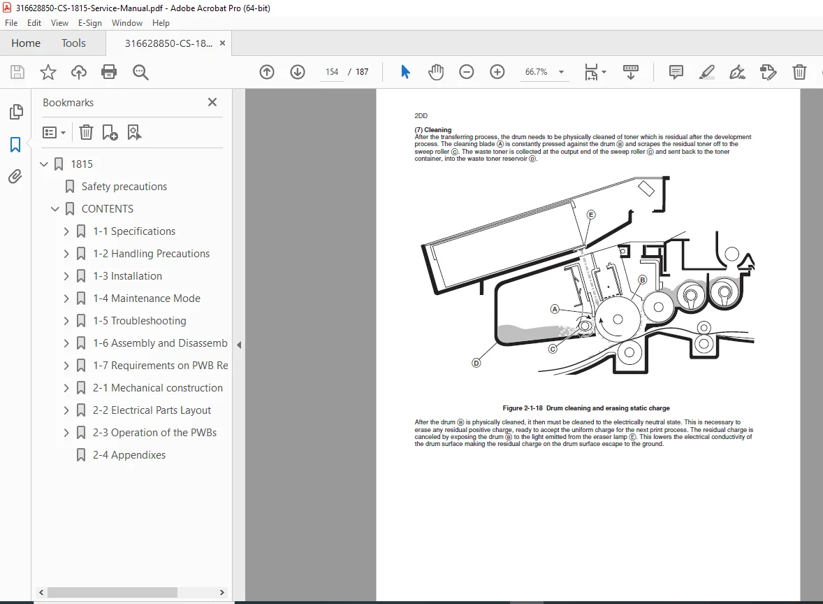
- Cleaning process
- Scanning System
- CCD sensor operation
- Optical system description
- Lamp and mirror assembly
- Scan motor drive system
- Image processing
- A/D conversion
- Laser Writing System
- Laser diode operation
- Polygon mirror assembly
- Beam detection system
- f-θ lens system
- Mirror positioning
- Paper Feed System
- Paper cassette mechanism
- Pick-up roller operation
- Feed roller system
- Registration mechanism
- Separation system
- Timing control
- Fusing System
- Heat roller assembly
- Pressure roller
- Temperature control
- Safety mechanisms
- Fusing pressure adjustment
- Control System
- Main controller board
- CPU operation
- Memory management
- I/O control
- Sensor monitoring
- Motor control circuits
CHAPTER 4: DISASSEMBLY & ASSEMBLY (Pages 126-198)
- Safety Precautions
- High voltage warnings
- Hot surface precautions
- Mechanical hazards
- Laser safety
- ESD protection
- Required Tools
- Standard hand tools
- Specialized tools
- Test equipment
- Measurement instruments
- Covers & Panels Removal
- Top cover removal
- Front cover disassembly
- Side panels removal
- Rear panel access
- Control panel removal
- Major Assembly Removal
- Scanner Unit Removal
- Disconnection procedures
- Mounting screw locations
- Cable routing notes
- Reinstallation guidelines
- Drum Unit Removal
- Cartridge extraction
- Developer removal
- Cleaning unit disassembly
- Assembly procedures
- Fusing Unit Removal
- Temperature sensor disconnection
- Mounting bracket removal
- Heat roller extraction
- Pressure roller removal
- Paper Feed Mechanism
- Cassette assembly removal
- Pick-up roller replacement
- Feed roller replacement
- Registration roller access
- Laser Unit Removal
- Optical unit extraction
- Polygon motor removal
- Mirror assembly disassembly
- Lens system removal
- Scanner Unit Removal
- Circuit Board Removal
- Main controller board
- Power supply board
- High voltage board
- Scanner control board
- Interface boards
- Sensor boards
- Drive System Components
- Main motor removal
- Clutch assemblies
- Gear train disassembly
- Belt replacement
- Solenoid removal
CHAPTER 5: ADJUSTMENTS & SETTINGS (Pages 199-248)
- Mechanical Adjustments
- Scanner Positioning
- Home position adjustment
- Scan timing adjustment
- Mirror alignment
- Lens position setting
- Registration Adjustment
- Registration roller timing
- Side registration
- Leading edge registration
- Skew correction
- Drum & Developer
- Drum-to-developer gap
- Developer bias adjustment
- Cleaning blade pressure
- Toner density setting
- Fusing System
- Fusing temperature setting
- Pressure adjustment
- Nip width setting
- Release agent application
- Scanner Positioning
- Electrical Adjustments
- Laser Power Adjustment
- Beam intensity setting
- Beam detection calibration
- Polygon motor speed
- High Voltage Settings
- Primary charging voltage
- Transfer voltage adjustment
- Separation voltage
- Development bias
- Sensor Calibration
- Paper detection sensors
- Toner density sensor
- Temperature sensors
- Position sensors
- Laser Power Adjustment
- Image Quality Adjustments
- Exposure adjustment
- Density calibration
- Background removal
- Copy contrast setting
- Sharpness adjustment
- White balance calibration
- Service Mode Settings
- Entering service mode
- Counter reading/reset
- Configuration settings
- Maintenance settings
- Test pattern printing
- Diagnostic procedures
CHAPTER 6: TROUBLESHOOTING (Pages 249-330)
- Systematic Diagnosis
- Problem symptom analysis
- Error code interpretation
- LED indicator meanings
- Service mode diagnostics
- Isolation techniques
- Image Quality Problems
- Blank Copies
- No toner development
- Laser not firing
- High voltage failure
- Exposure lamp problems
- Dark Copies/Solid Black
- Excessive charging
- Laser always on
- Developer bias issues
- Drum grounding problems
- Light Copies/Faint Images
- Low toner density
- Insufficient charging
- Weak laser output
- Worn drum surface
- Background Fog
- Incorrect bias voltage
- Dirty drum surface
- Improper development gap
- Contaminated developer
- White Spots/Voids
- Dirty scan glass
- Drum defects
- Foreign material
- Transfer problems
- Black Spots/Lines
- Dirty corona wires
- Drum damage
- Foreign material in paper path
- Fusing roller contamination
- Streaks & Bands
- Developer aging
- Uneven toner distribution
- Polygon motor issues
- Feed roller problems
- Blank Copies
- Paper Handling Problems
- Paper Jams
- Feed jam troubleshooting
- Registration jam
- Fusing area jams
- Exit jam diagnosis
- Jam location identification
- Misfeeds
- Multiple feed problems
- No feed conditions
- Feed roller wear
- Separation pad issues
- Paper Wrinkling
- Fusing pressure issues
- Moisture problems
- Paper path obstructions
- Paper Jams
- Electrical Problems
- Power Issues
- No power conditions
- Power supply failures
- Circuit breaker tripping
- Fuse identification
- Control Problems
- CPU not responding
- Communication errors
- Memory errors
- Sensor failures
- Motor Problems
- Main motor not running
- Polygon motor failure
- Fan motor issues
- Clutch not engaging
- Power Issues
- Scanner Problems
- Scan lamp not lighting
- Scan motor not moving
- Home position errors
- Image distortion
- CCD sensor failures
- Display & Control Panel
- Display not functioning
- Button not responding
- Error message display
- Incorrect status indication
CHAPTER 7: ERROR CODES (Pages 331-355)
- Error Code List
- Complete error code reference
- Error descriptions
- Probable causes
- Troubleshooting procedures
- Resolution steps
- Service Call Codes
- Maintenance required codes
- Component replacement codes
- Critical failure codes
- User-clearable errors
- LED Error Indicators
- Blinking pattern meanings
- Status light interpretation
- Warning conditions
- Service required indicators
CHAPTER 8: PREVENTIVE MAINTENANCE (Pages 356-378)
- Maintenance Schedule
- Daily maintenance tasks
- Weekly cleaning procedures
- Monthly inspection items
- Quarterly maintenance
- Annual service requirements
- Component life expectancy
- Cleaning Procedures
- Scanner Glass Cleaning
- Approved cleaning materials
- Cleaning frequency
- Proper techniques
- Corona Wire Cleaning
- Charging wire cleaning
- Transfer wire cleaning
- Cleaning tool usage
- Feed Roller Cleaning
- Pick-up roller maintenance
- Feed roller cleaning
- Separation pad cleaning
- Internal Cleaning
- Dust removal
- Toner waste removal
- Ventilation cleaning
- Optical component cleaning
- Scanner Glass Cleaning
- Lubrication
- Lubrication points
- Recommended lubricants
- Application procedures
- Lubrication intervals
- Component Replacement
- Consumable life counters
- Drum replacement schedule
- Developer replacement
- Fusing roller replacement
- Feed roller replacement
CHAPTER 9: CIRCUIT DIAGRAMS (Pages 379-410)
- System Block Diagrams
- Overall system architecture
- Power distribution
- Control signal flow
- Communication buses
- Detailed Schematics
- Main controller board circuits
- Power supply schematics
- High voltage power supply
- Scanner control circuits
- Motor drive circuits
- Sensor interface circuits
- Control panel interface
- PCB Layout Diagrams
- Component locations
- Board mounting positions
- Connector identifications
- Test point locations
- Jumper settings
- Wiring Diagrams
- Cable harness routing
- Connector pinouts
- Ground connections
- Interconnection diagrams
CHAPTER 10: PARTS CATALOG (Pages 411-428)
- Exploded View Diagrams
- Major assembly breakdowns
- Component relationships
- Assembly sequences
- Parts Lists
- Part numbers and descriptions
- Quantity per assembly
- Reference designations
- Replacement notes
- Alternative part numbers
- Ordering Information
- Parts ordering procedures
- Distributor contacts
- Service support information
- Warranty information
- Return procedures
✅ KEY FEATURES OF THIS SERVICE MANUAL
✔ Comprehensive Error Code Reference – Quick fault identification
✔ Detailed Disassembly Procedures – Step-by-step component removal
✔ Complete Circuit Schematics – Component-level repair guidance
✔ Image Quality Troubleshooting – Resolve copy defects
✔ Mechanical Adjustment Procedures – Ensure optimal performance
✔ Preventive Maintenance Schedules – Maximize equipment uptime
✔ Parts Catalog with Exploded Views – Accurate component ordering
✔ Service Mode Instructions – Advanced diagnostics access
🔧 WHO NEEDS THIS MANUAL?
- Copier Technicians – Office equipment service specialists
- Field Service Engineers – On-site copier repair professionals
- Service Center Technicians – Workshop repair specialists
- IT Support Staff – Corporate equipment maintenance
- Office Equipment Dealers – In-house service departments
- Maintenance Contractors – Commercial equipment service
- Technical Training Centers – Copier repair instruction
💡 WHAT YOU CAN ACCOMPLISH WITH THIS MANUAL
✅ Diagnose and repair image quality defects
✅ Resolve paper jam and feed problems
✅ Perform mechanical adjustments and calibrations
✅ Replace worn components correctly
✅ Clear error codes and restore operation
✅ Execute preventive maintenance schedules
✅ Access service mode for advanced diagnostics
✅ Order correct replacement parts using OEM numbers
🏢 CRITICAL FOR OFFICE PRODUCTIVITY
The Kyocera CS-1815 is a workhorse digital copier used in offices, schools, government agencies, and businesses. Proper maintenance and rapid troubleshooting minimize downtime and ensure consistent document reproduction. This service manual provides the technical knowledge needed to keep office equipment operating reliably and producing quality copies.
📥 INSTANT DIGITAL DELIVERY
Download immediately after purchase – No waiting for physical manuals! Get instant access to this comprehensive 428-page service manual and begin servicing your Kyocera CS-1815 copier immediately. PDF format works on all devices – computers, tablets, and smartphones. Print specific sections for shop floor reference or search digitally for quick troubleshooting.
🎯 WHY THIS MANUAL IS ESSENTIAL
This is the official Kyocera factory service documentation used by authorized service centers and office equipment technicians worldwide. Don’t waste time with incomplete troubleshooting information or risk equipment damage with improper repair procedures. This comprehensive manual provides exact specifications, adjustment procedures, and diagnostic steps required to maintain Kyocera CS-1815 copiers to manufacturer standards. Reduce downtime, improve copy quality, and ensure reliable operation with this professional-grade service manual!
Pricing Rationale:
- Official Kyocera factory service manual
- Comprehensive 428-page technical documentation
- Essential for copier technicians and service professionals
- Includes complete schematics, adjustments, and troubleshooting
- Detailed error code reference and image quality diagnostics
- Critical for office equipment service operations
- Comparable copier service manuals typically range $30-$40