
Landini 4-070D 4-080D 4-090D Tractor Service Manual 2019 – PDF Repair Guide
Original price was: $39.95.$24.95Current price is: $24.95.
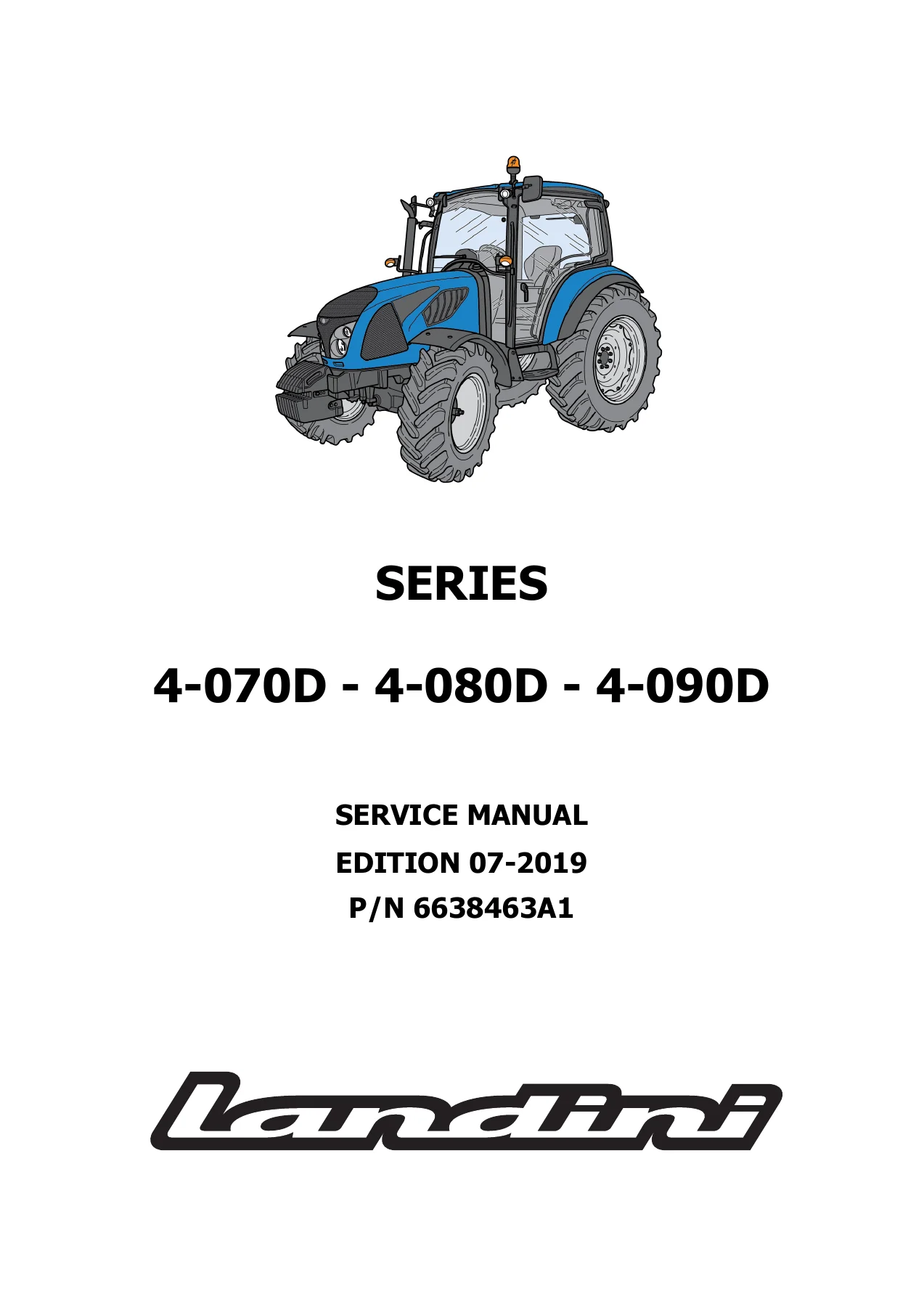
Complete 1,634-page Landini 4-070D, 4-080D and 4-090D Series tractor service manual (Edition 07-2019, P/N 6638463A1). Covers engine, transmission, gearbox, differential, final drives, PTO, front axle, brakes, hydraulics, steering, electrical and CAN-line diagnostics. Instant PDF download.
Description
Landini 4-070D, 4-080D and 4-090D Tractor Service Manual — 2019 Edition
This is the complete service manual for the Landini 4-070D, 4-080D and 4-090D Series tractors, published as Edition 07-2019 under reference number 6638463A1. Running to 1,634 pages, it is a full workshop-level document written for technicians carrying out diagnosis, repair, overhaul and adjustment on these machines. Coverage extends from the DEUTZ TCD 2.9 L4 engine through to the mechanical reverse shuttle transmission, synchronised gearbox and ranges, rear differential, side final drives, rear PTO, front axle, oil-cooled brakes, hydraulic system, power steering and the CAN-line electronic controllers.
File Details
- Manual type: Service Manual / Workshop Manual
- Brand: Landini (Argo Tractors S.p.A.)
- Models covered: 4-070D, 4-080D, 4-090D
- Engine family: DEUTZ TCD 2.9 L4 (TD 2.9 L4, TD 2.9 L4 HT, TD 2.9 L4 HP)
- Edition: 07-2019
- Publication number: 6638463A1
- Language: English
- Page count: 1,634
- File format: PDF
Chapters Covered
- Section 1001 — General Safety
- Section 2 — Engine (DEUTZ engine workshop manuals annexed)
- Section 2002 — Exhaust Gases Treatment System (DOC system, EGR valve)
- Section 3005 — Tanks and Reservoirs (fuel tank removal, cab and footstep versions)
- Section 4001 — Electric System (fuses, relays, wiring diagrams, connectors, cab and footstep)
- Section 4002 — Instrument Cluster Set-Up (menus, parameters, service intervals)
- Section 5 — Steering System Operation
- Section 5001 — Steering Column and Power Steering System
- Section 6 — Transmission Operation
- Section 6001 — Engine-Transmission Coupling
- Section 6002 — Engine-Gearbox Assembly (Mechanical Reverse Shuttle)
- Section 6006 — Synchronised Gearbox and Ranges
- Section 6012 — Rear Differential
- Section 6018 — Side Final Drives
- Section 6019 — Rear Power Take-Off (2 Speeds with Mechanical Engagement)
- Section 6021 — Front Axle
- Section 7 — Brakes Operation
- Section 7003 — Brake Adjustments and Inspections
- Section 8 — Hydraulic Components Operation
- Section 8001 — Hydraulic Inspections and Adjustments
- Section 8007 — Rear Hitch
- Section 10 — CAN Line Controllers
- Section 10005 — Engine Controller (error codes, troubleshooting, wiring diagrams)
- Section 10009 — Instrument Cluster Controller (descriptions, wiring diagrams, error codes, troubleshooting)
- Section 10010 — Controller Programming (Argo Tractors DIAG4)
What This Manual Gives You
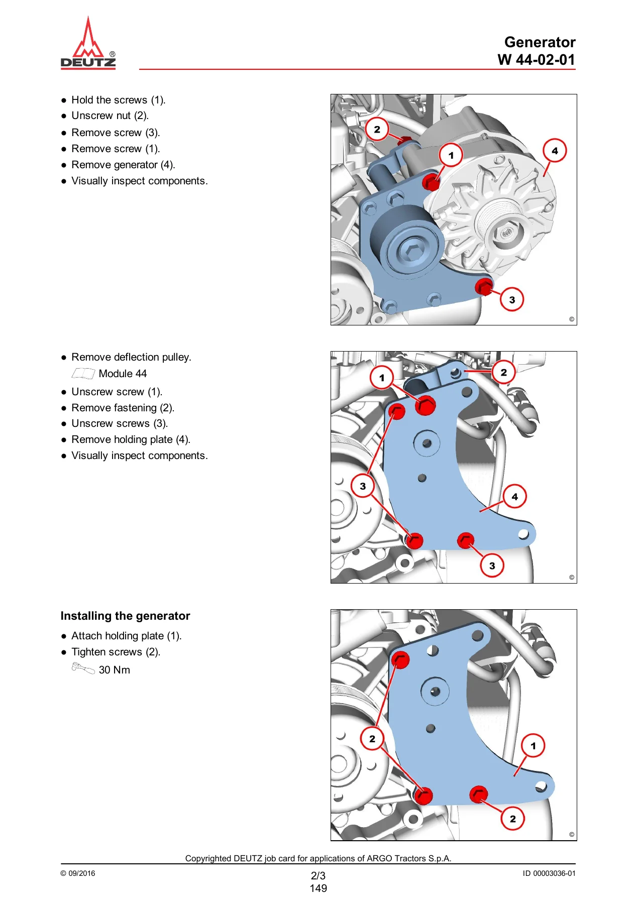
The 4-070D, 4-080D and 4-090D Series Service Manual is built around the way a workshop actually works on these tractors. Each section opens with its own index and technical specification table, then walks through the relevant assemblies with numbered exploded views, cross-section drawings, tightening torques and step-by-step procedures. The transmission section is particularly detailed — the engine-gearbox assembly, mechanical reverse shuttle, synchronised gearbox, range selection and creeper option are all broken down to component level. The four-wheel drive system, rear differential with diff lock, epicyclic side final drives and the rear PTO variants (540, 540E, 1000 RPM, independent and synchronised) each have dedicated coverage.
On the hydraulic side, the manual documents the dual-stage gear pump, priority valve, solenoid valve pack, rear hitch control valve, auxiliary control valves and mid-mount valves, with operating pressure tests and calibration values included in the inspections and adjustments section. The steering section covers the hydrostatic power steering system in neutral, steering and engine-off conditions, along with the steering column and splined shaft procedures.
Brake coverage includes the oil-cooled multi-plate rear brakes, expansion plate operation, parking brake linkage, brake pumps, shut-off valve and trailer brake valve types (Italian and Mother Regulation + EEC), with bleeding and adjustment procedures. The electrical section 4001 is unusually comprehensive — it includes complete wiring diagrams for cab and footstep versions, fuse and relay layouts for the SFR, SFT and PDU boxes, connector pinouts, component locations and the CAN network circuit. The engine controller (10005) and instrument cluster controller (10009) sections contain full SPN/FMI error code tables with diagnostic flowcharts, terminal checks, expected resistance and voltage values, and wiring references.
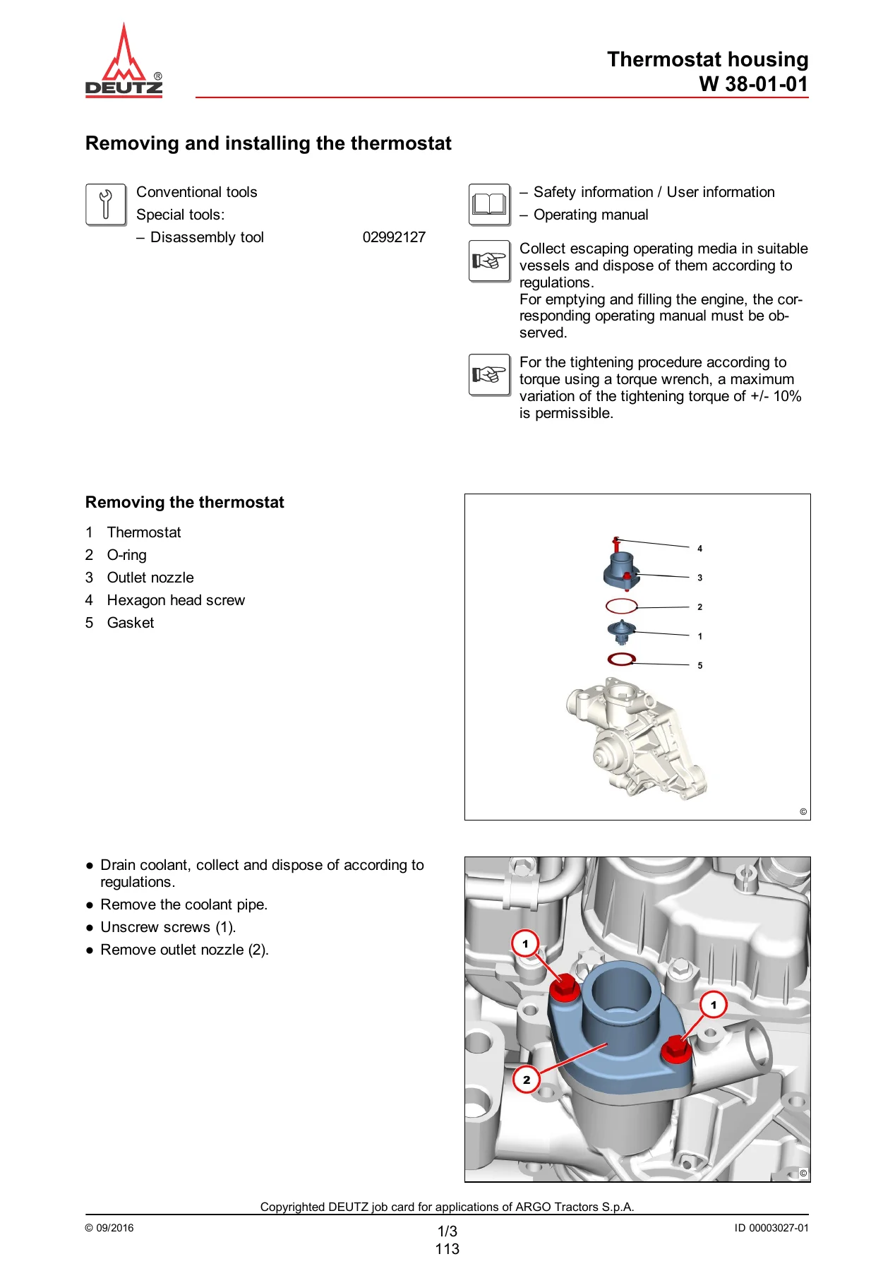
The engine coverage is supplemented by the annexed DEUTZ TCD 2.9 L4 workshop manual, which documents the common rail fuel system, injector removal and installation, high-pressure pump timing, EGR module and valve, exhaust turbocharger, coolant pump, thermostat, oil cooler, cylinder head cover, crankshaft sealing rings, drive flange, control valve and the special tools required for each job. The engine technical data — 2,900 cm³ swept volume, 92/110 mm bore, 2,200 RPM rated speed, 272 to 378 Nm maximum torque at 1,600 RPM, and the Tier 4F / Tier 4i emission levels — is listed alongside the EGR and DOC exhaust treatment details.
Who This Manual Is For
This Landini 4-070D, 4-080D and 4-090D service manual is aimed at workshop technicians, fleet maintenance staff and experienced owners who need the manufacturer’s procedures rather than generic advice. It assumes access to normal workshop equipment and, in places, to the special tools called out in the text — torque multipliers, ring nut wrenches, bearing installers, extraction devices, the SerDia 2010 diagnostic tool and the Argo Tractors DIAG4 programming system. The procedures are written to be followed in sequence, with the tightening torques, service limits and adjustment values stated at the point of use.
If you are servicing the DEUTZ TCD 2.9 L4 engine, overhauling the mechanical reverse shuttle or synchronised gearbox, repairing the rear differential or final drives, setting up the PTO, bleeding the brakes, testing hydraulic pressures, or diagnosing a CAN-line fault code on a 4-070D, 4-080D or 4-090D, this manual contains the information needed to do the job correctly.
Why It Matters
These tractors use systems that do not respond well to guesswork. The common rail fuel system operates at pressures where a mistake can be dangerous, the transmission and final drives rely on precise bearing preloads and shimming, and the electronic controllers need the correct parameter set-up to function. Working from the manufacturer’s procedures and specifications is the difference between a repair that lasts and one that comes back. Having the complete wiring diagrams and error code tables on hand also cuts diagnostic time significantly, especially on the CAN network and the engine and instrument cluster controllers.
Delivery
IMAGES PREVIEW
The manual is supplied as a PDF file, available for immediate download after payment. There is no shipping and no waiting for a physical book. You can open it on a computer, tablet or phone, search the text, zoom into the diagrams, and print the pages you need for the workshop. The file is the complete 1,634-page Edition 07-2019 document, reference 6638463A1.

Reviews
There are no reviews yet.