Lexmark X7500 All-in-One Printer Service Repair Manual Multifunction – PDF
Original price was: $95.00.$17.95Current price is: $17.95.
Complete factory service manual for Lexmark X7500 (4036-501) all-in-one multifunction printer. Comprehensive technical documentation includes DADF auto document feeder repair, scanner troubleshooting, diagnostic procedures, removal/replacement instructions, wiring diagrams, parts catalog, preventive maintenance schedules, and adjustment procedures. Features detailed exploded view diagrams and connector locations. Essential professional reference for printer technicians servicing multifunction devices.
Description
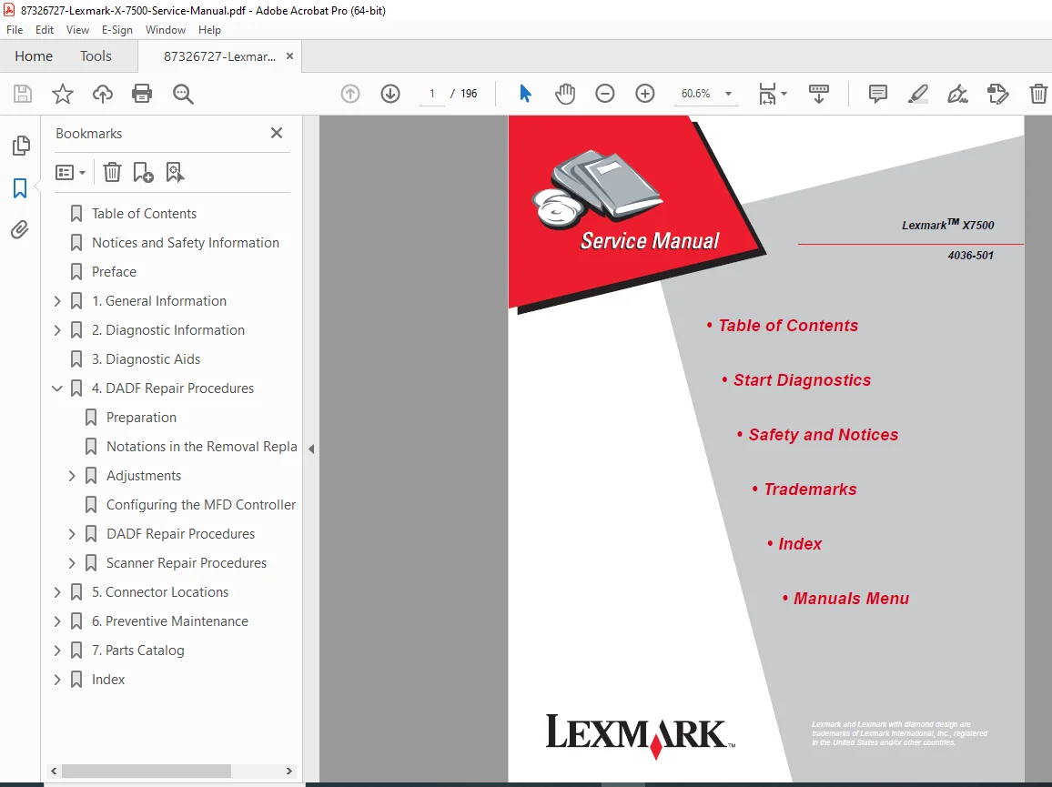
Lexmark X7500 All-in-One Printer Service Repair Manual Multifunction 4036 – PDF DOWNLOAD
DESCRIPTION
This is the complete official Lexmark X7500 Service Manual (Model 4036-501, October 2001 Edition) for professional all-in-one multifunction printers. This comprehensive factory service manual provides professional-grade troubleshooting, repair, and maintenance information for authorized service technicians servicing this multifunction device combining printing, scanning, copying, and faxing capabilities.
Equipment Covered by This Service Manual
Lexmark X7500 Multifunction Printer:
- Model Number: 4036-501
- Product Type: All-in-One Multifunction Device (MFD)
- Functions: Print, Scan, Copy, Fax
- Technology: Inkjet printer with flatbed scanner
- Document Feeder: Duplex Auto Document Feeder (DADF)
Manufacturer:
- Lexmark International, Inc.
- Department D22A/032-2
- 740 West New Circle Road
- Lexington, Kentucky 40550, U.S.A.
Equipment Type:
- Consumer/business all-in-one printer
- Multifunction peripheral
- Inkjet technology
- Flatbed scanner with ADF
Complete Manual Contents (196 Pages)
This Lexmark X7500 service manual PDF is organized into comprehensive chapters with interactive navigation:
INTERACTIVE TABLE OF CONTENTS
Main Sections (Clickable Navigation):
- Table of Contents
- Start Diagnostics
- Safety and Notices
- Trademarks
- Index
- Manuals Menu
NOTICES AND SAFETY INFORMATION (PAGES vii-ix)
Safety Information (Multi-Language):
English:
- Product designed to meet strict global safety standards
- Use only specific Lexmark components
- Professional service personnel only
- Increased risk of electric shock during servicing
- Proper precautions required
French (Consignes de Sécurité):
- Safety standards compliance
- Qualified maintenance personnel
- Electrical risk awareness
Italian (Norme di sicurezza):
- Safety requirements
- Authorized service personnel
- Shock hazard precautions
German (Sicherheitshinweise):
- Safety compliance
- Qualified technicians required
- Proper safety measures
Spanish (Pautas de Seguridad):
- Safety design verification
- Professional service requirements
Legal Notice:
- © Copyright Lexmark International, Inc. 2001
- Publication provided “AS IS”
- No warranty expressed or implied
- Technical inaccuracies may exist
- Changes made periodically
- U.S. Government Restricted Rights
Part Numbers:
- U.S.A. P/N: 12G9083
- Japanese P/N: (specified separately)
PREFACE (PAGE x)
Manual purpose and intended audience
CHAPTER 1: GENERAL INFORMATION (PAGES 1-1 TO 1-30)
1.1 Maintenance Approach (Page 1-1)
- Service philosophy
- Diagnostic methodology
- Repair strategy
1.2 Tools Required for Service (Page 1-1)
- Standard hand tools
- Specialized tools
- Test equipment
- Safety equipment
1.3 Acronyms (Page 1-2)
- DADF: Duplex Auto Document Feeder
- MFD: Multifunction Device
- CCD: Charge Coupled Device
- Technical abbreviations
1.4 Preparing the Scanner for Shipping (Page 1-3)
- Packaging procedures
- Transport lock installation
- Shipping precautions
1.5 Duplex Auto Document Feeder (DADF) Principles of Operation (Pages 1-4 to 1-22)
DADF Power (Page 1-4):
- Power distribution
- Voltage specifications
- Power management
DADF Control (Pages 1-4+):
- Controller architecture
- Control signals
- Motor control
- Sensor inputs
- Solenoid operation
- Paper path control
- Duplex scanning operation
1.6 Scanner Principles of Operation (Pages 1-23 to 1-30)
Scanner Power (Page 1-23):
- Power supply
- Voltage distribution
- Power consumption
Scanner Control (Pages 1-24 to 1-27):
- Scanner controller
- Carriage control
- Lamp control
- Sensor management
- Position detection
Mechanical Drive (Pages 1-28 to 1-29):
- Drive motor
- Belt drive system
- Carriage movement
- Full rate/half rate carriages
Scanning Methods (Page 1-30):
- Flatbed scanning
- ADF scanning
- Resolution control
- Speed control
CHAPTER 2: DIAGNOSTIC INFORMATION (PAGES 2-1 TO 2-12)
2.1 Start (Page 2-1)
- Initial troubleshooting approach
- Problem identification
2.2 Scanner Errors (Pages 2-2 to 2-3)
- Scanner error codes
- Error descriptions
- Troubleshooting guidance
2.3 MFD Controller Cage Errors (Pages 2-4 to 2-6)
- Controller error codes
- System errors
- Communication errors
2.4 Symptom Tables (Pages 2-7 to 2-12)
- Problem symptoms
- Possible causes
- Corrective actions
- Quick reference troubleshooting
CHAPTER 3: DIAGNOSTIC AIDS (PAGES 3-1+)
- Diagnostic tools
- Test procedures
- Verification methods
- Performance testing
CHAPTER 4: REPAIR PROCEDURES (PAGES 4-1 TO 4-71)
4.1 Preparation (Page 4-1)
- Service preparation
- Safety precautions
- Workspace setup
4.2 Notations in Removal/Replacement Text (Page 4-2)
- Symbol explanations
- Procedure conventions
- Important notes
4.3 Adjustments (Pages 4-3 to 4-8)
DADF Assembly Height Adjustment (Page 4-3):
- Height calibration
- Measurement procedure
- Adjustment technique
DADF Assembly Paper Skew Adjustment (Pages 4-4 to 4-5):
- Skew detection
- Correction procedure
- Verification testing
Adjusting Position of Full Rate/Half Rate Carriages (Pages 4-6 to 4-7):
- Carriage alignment
- Position calibration
- Optical adjustment
Configuring MFD Controller Card (Page 4-8):
- Controller configuration
- DIP switch settings
- Jumper positions
4.4 DADF Repair Procedures (Pages 4-9 to 4-47)
Component Removal/Replacement Procedures:
- DADF Assembly Removal (Pages 4-9 to 4-10)
- DADF Front Cover, Handle, and Magnet (Page 4-11)
- DADF Cushion (Pages 4-12 to 4-13)
- DADF Exit/Reverse Solenoid (Page 4-14)
- DADF Input Tray Assembly (Page 4-15)
- DADF Jam Access Door Assembly (Pages 4-16 to 4-17)
- DADF Top Cover (Page 4-18)
- DADF Rear Cover (Page 4-19)
- DADF Jam Door Open Switch (Page 4-20)
- Mylar Paper Guide Strip (Page 4-21)
- DADF Left and Right Hinge (Pages 4-22 to 4-23)
- DADF Controller Card Assembly (Pages 4-24 to 4-25)
- DADF Registration Roll Drive Motor Assembly (Pages 4-26 to 4-27)
- DADF Main Drive Motor Assembly (Pages 4-28 to 4-29)
- DADF Separator Pad Assembly (Page 4-30)
- DADF Separator Pad (Page 4-31)
- DADF #1 and #2 Linkage (Page 4-32)
- Linkage Cover (Page 4-33)
- Paper Stop Spring and Paper Stop (Pages 4-34 to 4-35)
- DADF Roller Engagement Shaft Assembly (Pages 4-36 to 4-37)
- DADF Paper Present Sensor (Page 4-38)
- DADF Paper Present Indicator Card Assembly (Page 4-39)
- Paper Present Sensor Flag (Page 4-40)
- DADF Pick Roller with Separator Pad Kit (Page 4-41)
- Registration Sensor (Page 4-42)
- DADF Gear #3 Bearing (Page 4-43)
- Tension Roller Spring and Tension Roller (Page 4-44)
- DADF Upper Paper Guide (Page 4-45)
- DADF #4 Gear (Pages 4-46 to 4-47)
4.5 Scanner Repair Procedures (Pages 4-48 to 4-71)
Scanner Component Removal/Replacement:
- User Interface Panel (Page 4-49)
- Flatbed Scanner Top Cover Assembly (Pages 4-50 to 4-51)
- Flatbed Center Platen Glass Plate (Pages 4-52 to 4-53)
- Left DADF Platen Glass Plate (Page 4-54)
- Scanner Main Drive Motor Assembly (Page 4-55)
- Scanner Motor Card Assembly (Page 4-56)
- Flatbed Open Sensor (Page 4-57)
- Registration Sensor Assembly (Page 4-58)
- Plate Switch Assembly (Page 4-59)
- Scanner System Card Assembly (Pages 4-60 to 4-61)
- Charge Coupled Device (CCD) Card Assembly (Pages 4-62 to 4-63)
- Automatic Paper Size Sensor (Page 4-64)
- Full Rate Carriage Lamp Assembly (Page 4-65)
- Cable Assembly – Scan, Rear (Pages 4-66 to 4-70)
- Full Rate Carriage Lamp Cable (Page 4-71)
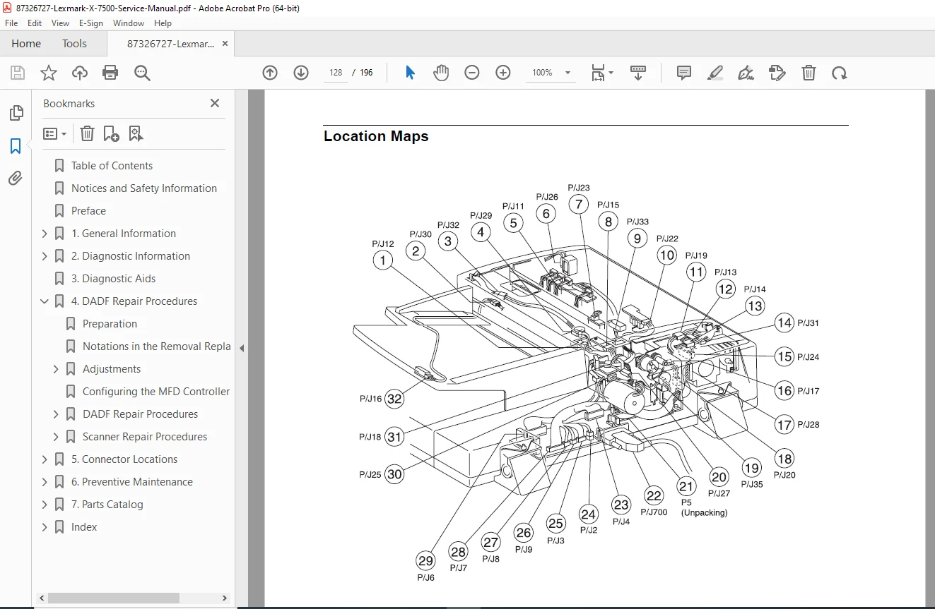
CHAPTER 5: CONNECTOR LOCATIONS (PAGES 5-1 TO 5-25)
5.1 Location Maps (Pages 5-2 to 5-7)
- Component location diagrams
- Connector identification
- Board layouts
- Visual reference guides
5.2 Wiring Diagrams and Signal Information (Pages 5-8 to 5-25)
DADF Master Wiring Diagram (Pages 5-9 to 5-16):
- Complete electrical schematic
- Power distribution
- Signal routing
- Connector pin-outs
- Motor connections
- Sensor wiring
- Solenoid circuits
Scanner Master Wiring Diagram (Pages 5-17 to 5-25):
- Scanner electrical schematic
- Controller connections
- Motor wiring
- Sensor circuits
- Lamp power
- CCD connections
- Interface signals
CHAPTER 6: PREVENTIVE MAINTENANCE (PAGES 6-1 TO 6-4)
6.1 Maintaining Your Multifunction Product (MFP) (Page 6-1)
Cleaning the Touch Screen:
- Cleaning materials
- Procedure
- Frequency
Cleaning the Scanner Bed (Page 6-1):
- Glass cleaning
- Cleaning solution
- Streak prevention
Cleaning the Scanner Rollers (Pages 6-1 to 6-2):
- Roller access
- Cleaning procedure
- Pick roller maintenance
- Feed roller care
Cleaning the Scanner Pick Pads (Pages 6-3 to 6-4):
- Pad location
- Cleaning technique
- Replacement criteria
Maintenance Schedule:
- Daily tasks
- Weekly procedures
- Monthly maintenance
- Replacement intervals
CHAPTER 7: PARTS CATALOG (PAGES 7-1 TO 7-28)
7.1 How to Use This Parts Catalog (Page 7-1)
- Catalog organization
- Part number format
- Ordering information
Assembly Diagrams with Part Numbers:
Assembly 1: DADF Cover and Solenoid (Pages 7-2 to 7-3)
- Exploded view diagram
- Part numbers and descriptions
- Quantities
Assembly 2: DADF Cover, Switch, and Hinge (Rear) (Pages 7-4 to 7-5)
- Component identification
- Part listings
Assembly 3: DADF Control Board and Registration Roll Drive Motor (Pages 7-6 to 7-7)
- Electronic components
- Motor assembly parts
Assembly 4: DADF Separator Pad Assembly and Paper Stop (Pages 7-8 to 7-9)
- Paper handling parts
- Separation components
Assembly 5: DADF Pick Roller (Pages 7-10 to 7-11)
- Pick mechanism
- Roller assemblies
Assembly 6: DADF Document Registration (Pages 7-12 to 7-13)
- Registration components
- Sensor parts
Assembly 7: DADF Wiring Harness (Pages 7-14 to 7-15)
- Cable assemblies
- Connector parts
Assembly 8: Scanner Platen Glass and IPS PWB (Pages 7-16 to 7-17)
- Glass components
- Circuit boards
Assembly 9: Scanner Lens Assembly and CCD Card (Pages 7-18 to 7-19)
- Optical components
- Imaging sensor
Assembly 10: Scanner Carriage Motor and Cable (Pages 7-20 to 7-21)
- Drive components
- Cable assemblies
Assembly 11: Scanner Full Rate and Half Rate Carriage (Pages 7-22 to 7-23)
- Carriage assemblies
- Mirror components
Assembly 12: Scanner Top Cover (Pages 7-24 to 7-25)
- Cover components
- Hinge parts
Assembly 13: Multifunction Device Controller Cage Electronics (Pages 7-26 to 7-28)
- Controller boards
- Electronic assemblies
- Interface cards
INDEX (MULTIPLE PAGES)
- Comprehensive alphabetical index
- Cross-references
- Quick topic location
Key Features
Multifunction Device:
- All-in-one functionality
- Print, scan, copy, fax
- Duplex document feeder
- Flatbed scanner
- Inkjet printing
DADF System:
- Automatic document feeding
- Duplex scanning capability
- Multiple page handling
- Paper path control
- Jam detection
Scanner Components:
- Flatbed scanner bed
- CCD imaging sensor
- Full rate/half rate carriages
- Lamp assembly
- Optical system
Professional Service Manual:
- Factory procedures
- Exploded view diagrams
- Complete wiring schematics
- Part number catalog
- Troubleshooting guides
Professional Service Features
Factory Documentation:
- Published by Lexmark International, Inc.
- October 2001 Edition
- Part number 12G9083
- Professional service level
Comprehensive Coverage:
- Complete disassembly procedures
- Adjustment instructions
- Wiring diagrams
- Parts catalog
- Troubleshooting aids
Visual Aids:
- Exploded view diagrams
- Component photographs
- Wiring schematics
- Connector locations
- Assembly illustrations
Interactive Features:
- Clickable table of contents
- Quick navigation
- Cross-referenced procedures
Who Should Use This Manual?
This multifunction printer repair guide is essential for:
- Professional printer service technicians
- Lexmark authorized service centers
- Electronics repair specialists
- IT support professionals
- Office equipment technicians
- Technical training institutions
Required Knowledge:
- Printer/scanner technology
- Electronic troubleshooting
- Mechanical assembly
- Safety procedures
- Basic electrical knowledge
Important Service Notes
Professional Service Only: Lexmark X7500 requires:
- Professional service personnel
- Proper safety precautions
- Genuine Lexmark components
- Authorized procedures
- Qualified technicians
Safety Critical:
- Electric shock hazard during servicing
- Proper disassembly procedures
- Safety precautions required
- Professional understanding necessary
Warranty Considerations:
- Use only Lexmark components
- Follow factory procedures
- Maintain service records
- Authorized service required
Quality Standards:
- Designed to strict safety standards
- Tested and approved components
- Global safety compliance
FILE DETAILS
| Attribute | Details |
|---|---|
| Manual Name | Lexmark X7500 Service Manual |
| Model Number | 4036-501 |
| Edition | October 2001 |
| Equipment Type | All-in-One Multifunction Printer |
| Functions | Print, Scan, Copy, Fax |
| Technology | Inkjet with Flatbed Scanner and DADF |
| Manufacturer | Lexmark International, Inc. |
| Manual Type | Factory Service & Repair Manual |
| Part Number (U.S.A.) | 12G9083 |
| File Format | PDF (Letter size pages) |
| File Size | ~4.3 MB |
| Total Pages | 196 pages |
| PDF Quality | Factory manual with interactive navigation |
| Language | English (with multi-language safety notices) |
| Creator | FrameMaker 6.0 |
| Copyright | © 2001 Lexmark International, Inc. |