
Liebherr CBW 40/29.5 ST Cargo Deck Crane Technical Information Manual – Volume 2
Original price was: $34.95.$19.95Current price is: $19.95.
Volume 2 Technical Information for the Liebherr CBW 40/29.5 ST cargo deck crane (Order 162 001-040) — hydraulic function descriptions, electrical technical data, emergency operating procedures, oil pressure tables and reference drawings.
Description
Liebherr CBW 40/29.5 ST Cargo Deck Crane — Volume 2 Technical Information
This is the second volume of the technical documentation set for the Liebherr CBW 40/29.5 ST cargo deck crane, issued under Order No. 162 001-040, Mod. no. 11 989. Where Volume 1 covers instruction and maintenance, this Volume 2 Technical Information manual goes deeper into the engineering behind the crane: how the hydraulic functions are built and controlled, how the electrical installation is structured, how to bring the crane down safely when the main motor has stopped, and where the pressure and specification values live.
The document is written for trained service personnel — the foreword states plainly that it is prepared for extended service, repair and maintenance work as well as ordering spare parts, and that it is intended for trained service personnel only. If you work on a CBW 40/29.5 ST, this is the volume that explains the machinery rather than just listing the periodic tasks.
File Details
- Manual type: Technical Information (Volume 2 of a three-volume documentation set)
- Brand / Manufacturer: Liebherr
- Crane type: CBW 40 / 29,5 ST cargo deck crane
- Order number: 162 001 – 040
- Modification number: 11 989
- Editions: 1st Edition 14.07.2000; 2nd Edition 29.08.2000
- Language: English (bilingual English/German headings and drawing annotations)
- Pages: approx. 209
- File format: PDF
Chapters Covered
The manual follows a logical structure from general data through to the reference drawings. The chapter list includes:
- 4. Technical Description — 4.1 Technical Data: general data, working speeds, hydraulic oil, drive system, lighting, heating
- 4.2 Technical Description – Electric — power supply, installed power ratings, switch cabinet X1, operation of main breaker, emergency stop function, operation of main motor (hydraulic drive), ventilation and heating, maintenance
- 5. Description of Hydraulic Functions — 5.1 General; 5.2 Description of the Main Hydraulic Components: variable swash plate pump A11VO LRDS, variable displacement motor A6V, control block LUDV, slewing safety block valve, lowering brake valve, hydraulically operated joystick TH6; 5.3 Explanation of Hydraulic Control System (LUDV function, single-user and two-user operation); 5.4 Hoist Motion; 5.5 Slew Motion; 5.6 Jib Motion; 5.7 Oil Cooler Circuit; 5.8 Oil Pressure Table
- 6. Emergency Operations — 6.1 Instructions for emergency hand pump (main motor standstill only); 6.2 Procedure to “lower the load” for hoisting gear; 6.3 Procedure to lower the jib (with hook block in parking position / with empty hook block); 6.4 Procedure to release the slewing brakes
- 7. Drawings — general arrangement and reeving plans, hydraulic schematic, and a full set of electrical drawings (outline power supply, switch cabinet X1, switch unit X20, cable entries slip ring column, electric wiring diagram, and add-on equipment schematics including load & radius limit, hoisting gear limitation, luffing gear/slewing gear sectors, working cage winch, base column lighting, floodlights, and ammeter)
Taken as a whole, the volume gives a technician a complete picture of the crane’s power transmission chain — from the 440 V / 60 Hz ship supply through the slip-ring collector, into the squirrel-cage main motor, through the flanged axial piston and gear pumps, into the LUDV control block and out to the hoist, luffing and slewing motions. The hydraulic descriptions are the heart of the book: the A11VO LRDS pump section explains constant power control, integral pressure cut-off and load sensing; the A6V motor section explains proportional displacement control and pressure limitation; and the LUDV section explains how oil is split between simultaneously operated users under saturation. The electrical section documents how the crane is started, stopped, protected and shut down in an emergency. The oil pressure table and the emergency procedures section round out the operational picture, and the drawing register tells you exactly which diagram sheet to turn to for each subsystem.
What the Technical Information Volume Covers in Detail
Hydraulic component descriptions
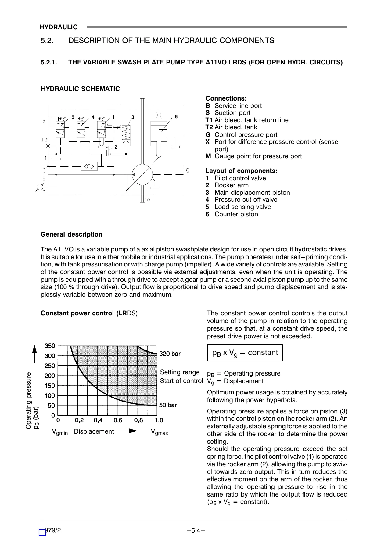
The component-level write-ups are unusually thorough for a technical information volume. The A11VO LRDS variable swash plate pump section works through the swashplate design, the through-drive arrangement, and the three superimposed control functions — load sensing, constant power control and integral pressure cut-off — with the power hyperbola relationship and the factory setting ranges given for each frame size. The A6V variable displacement motor section explains the open/closed circuit usage, the proportional control pressure at connection X, the low-speed/high-torque default position, and the pressure cutting valve that limits displacement control when working pressure is exceeded. The LUDV control block section covers the pressure scale valve, the sense bore, the pressure limiting valves on working and system pressure, and the behaviour of multiple users both below and above pump saturation — including the worked example of flow distribution when a 100 l/min pump feeds users needing 80% and 50%.
Hydraulic control system behaviour
The explanation of the LUDV control system covers the single-user case (hoisting), the two-user case with different working pressures and full speed (saturation mode), and the more-than-two-users case where total oil consumption exceeds maximum pump output. The distribution of flow is explained, along with the resulting drop in pressure difference between pump and highest working pressure. This is the kind of operational theory that helps a technician understand why a crane behaves the way it does when several motions are commanded at once.
Hoist, slew and jib motion
Each motion gets its own sub-chapter covering limits (solenoid valves Y01/Y02 for hoisting and luffing), feed pressure safety via check valves, variable hoisting motor control, protection against excessive pressure, control pressure limitation, and damping of slewing moment. The hoist section details the 310 bar working pressure limit and the 30 bar pressure switch that stops lifting below the working range; the slew section details the 300 bar limit and the control damping block; the jib section details the 360 bar lifting limit, the 150 bar annular area limit, the 400 bar shock pressure valve and the two hose fracture safety valves at the bottom of the luffing cylinders.
Oil cooler circuit
The combined hydraulic oil and winch gear oil cooler is described with its thermostat valve operation — oil routed through the cooler above 60°C and bypassed below 60°C, with the pressure before the cooler limited to approx. 9 bar.
Oil pressure table
A consolidated table lists system-by-system adjustable pressures and where each is set — from the 400 bar maximum working pressure on the LUDV block down to the 17 bar reduced control pressure for hoisting during simultaneous operation, and the 20 bar load sensing pressure on the A11VO pumps.
Emergency operations
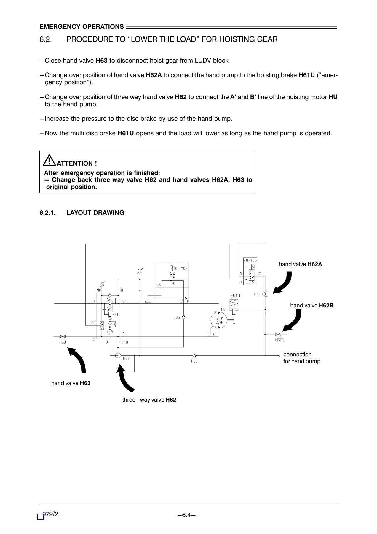
The emergency procedures are given step-by-step with layout drawings for each. Lowering the load through the hoisting gear, lowering the jib with the hook block in parking position or with an empty hook block, and releasing the slewing brakes are all covered, along with the valve positions to change and the warnings about supervising the movement and restoring all valves to operational position afterwards.
Why This Volume Matters for CBW 40/29.5 ST Service Work
Volume 1 tells you what to do and when. Volume 2 tells you why it works and how the systems are put together. That difference matters when a fault isn’t a simple worn part. Understanding the LUDV control logic, the pump’s load sensing behaviour, the motor’s displacement control and the interaction between the pressure limiting valves is what allows a technician to diagnose a slow or unresponsive motion, a saturated multi-function command, or a pressure-related shutdown instead of just replacing components until something changes. The emergency procedures alone are worth having on hand — they assume the main motor has stopped and the hydraulically released multi-disc brakes have closed, and they walk through releasing those brakes with the hand pump so the load or jib can be brought down under control.
IMAGES PREVIEW
Instant PDF Delivery
The manual is delivered as a PDF immediately after purchase — no shipping, no waiting for a physical copy. It opens on any device with a PDF reader and can be printed if you prefer a paper copy in the workshop. Whether you’re on a vessel, in a shipyard or at a service bench, having the technical information on hand means you can look up the hydraulic function, the pressure setting or the emergency procedure at the moment you need it rather than hunting through a filing cabinet.

Reviews
There are no reviews yet.