
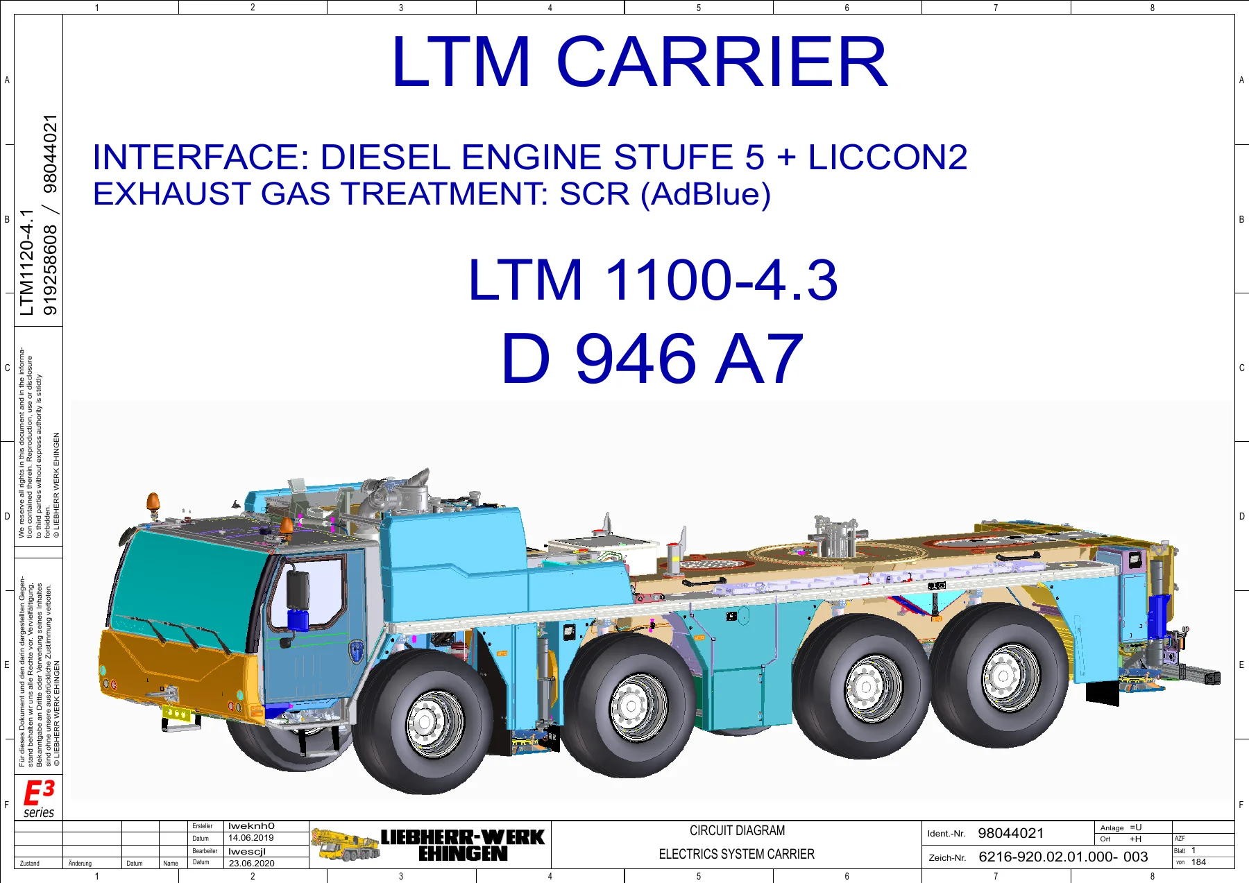
Liebherr LTM 1100-4.3 D946 A7 LICCON2 Electrical Circuit Diagrams – Engine & Exhaust Treatment SCR PDF
Original price was: $44.95.$26.95Current price is: $26.95.
406-page Liebherr electrical circuit diagram manual for the LTM 1100-4.3 with D 946 A7 engine and LICCON2. Covers diesel engine electrics, SCR/AdBlue exhaust gas treatment, CAN networks, LSB modules, sensor wiring, plug and fuse groupings.
Description
Liebherr LTM 1100-4.3 D946 A7 LICCON2 Electrical Circuit Diagrams – Engine & Exhaust Treatment
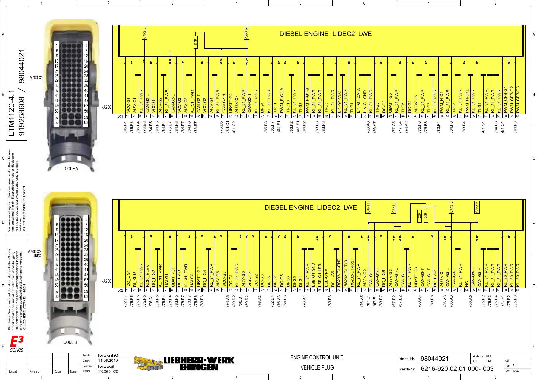
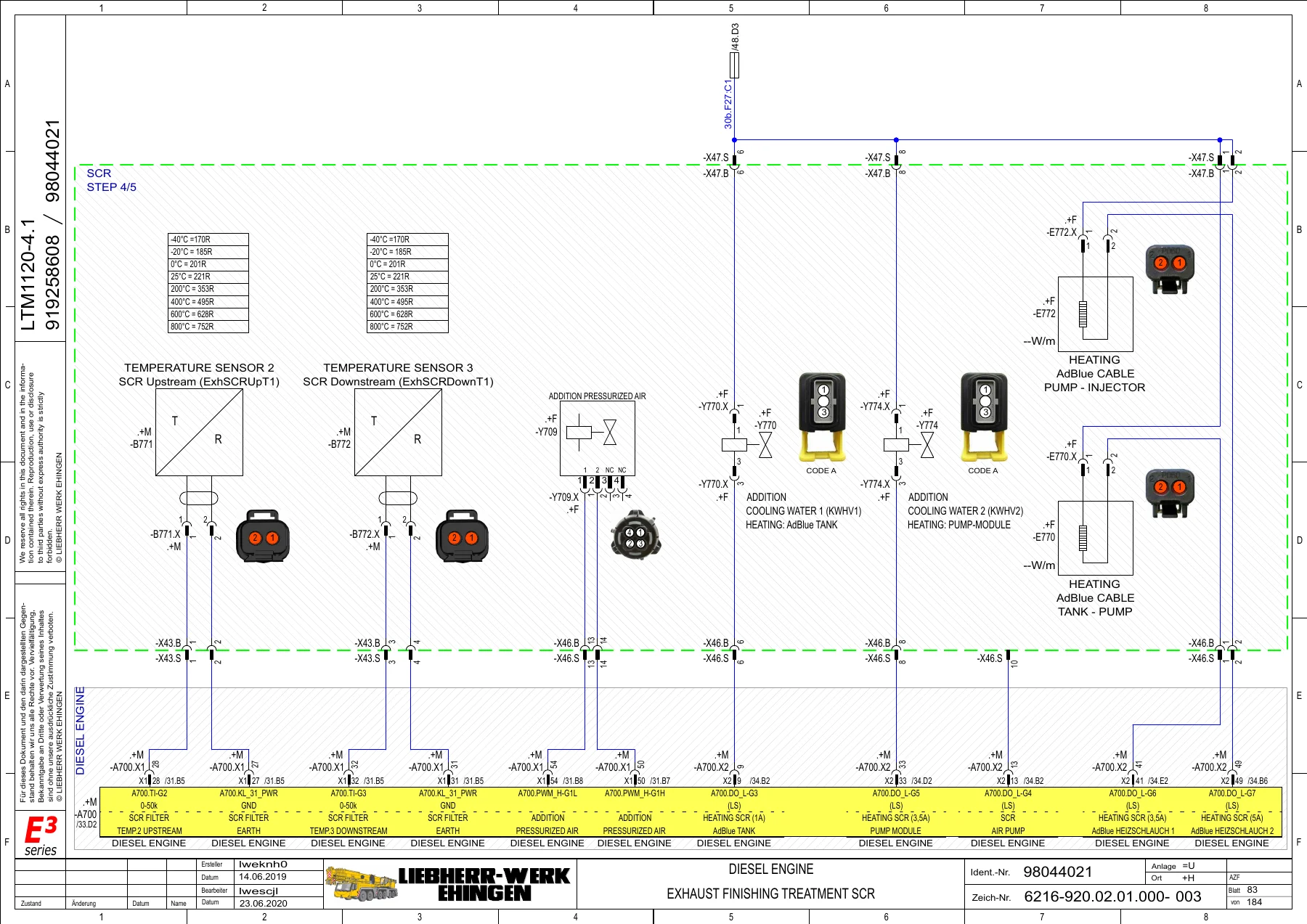
This is the dedicated electrical circuit diagram manual for the Liebherr LTM 1100-4.3 mobile crane equipped with the D 946 A7 diesel engine (Stage 5 / Stufe 5) and the LICCON2 crane control system. The document focuses specifically on the electrical architecture of the engine management and exhaust gas treatment systems, including the SCR (AdBlue) circuit paths that run through the carrier and superstructure. Every sheet is built as a proper circuit diagram: wire numbers, connector designations, pin assignments, component symbols, and cross-references are all shown in the standard Liebherr layout used by their workshop electricians.
File Details
- Manual type: Electrical Circuit Diagrams / Wiring Schematics
- Brand: Liebherr
- Model: LTM 1100-4.3
- Engine: D 946 A7 (Diesel Engine Stufe 5)
- Control system: LICCON2
- Subject: Engine and Exhaust Gas Treatment (SCR / AdBlue)
- Document numbers: 98044021 / 919258608
- Drawing number: 6216-920.02.01.000-003
- Language: English with German technical terminology
- Page count: 406
- File format: PDF
- Date: 14.06.2019, revised 23.06.2020
Chapters Covered
- Circuit Diagram Electrics System Carrier
- ABV Control Device – Driver’s Cab and General Layout
- ABV Hill Start Aid
- CAN 1 (J1939) – Vehicle network diagram
- CAN 2 (IES) – General layout
- CAN 3 (IES) – Vehicle network
- CAN 5 (J1939) – Layout
- CAN LIDEC (Diesel Engine)
- CAN LIDEC (Diesel Engine) Exhaust Gas Treatment SCR
- CAN ZF (J1939) – Transmission network
- Diesel Engine Accelerator
- Diesel Engine Diagnosis
- Diesel Engine ECU Supply
- Diesel Engine Exhaust Finishing Treatment SCR / SCRF
- Diesel Engine Fan Valve
- Diesel Engine High Pressure Pump / Waste-gate
- Diesel Engine Injector 1-6
- Diesel Engine Pressure Sensor
- Diesel Engine RPM Sensor
- Diesel Engine Temperature Sensor
- Batteries / Battery Temperature Sensor
- Charging / Generator
- Cooling Water Level and Cooling Water Sensor
- Starter circuit
- Exhaust Gas Treatment SCR (AdBlue)
- Intarder / Intarder Control Device
- Transmission Control Device and Diagnosis
- Mass Distribution (Vehicle and Superstructure)
- Voltage Supply coding and distribution
- LSB-BTB, LSB 1 through LSB 8 modules
- LSB-I/O-Module 1 to 4 (Driver’s Cab and General Layout)
- Display Unit Driver’s Cab Type G
- Key Board Unit Driver’s Cab Type G
- General Layout Lighting (front, rear, side, sliding beams)
- General Layout Cable Installation Carrier
- Plug Groupings -A, -AF, -B, -E, -F…K, -M…P, -R…S, -S…W, -X, -Y
- Fuse Grouping sheets (multiple)
- Fuses Driver’s Cab sheets
- BMK Index sheets
- Description of Symbols sheets
- Key of Symbols DIN-Standards
- Outline of Device
- Loom of Cables
Across these sheets the manual maps out the full electrical signal chain for the LTM 1100-4.3 carrier and superstructure electrical system: the CAN data buses that carry engine and transmission information, the LSB (Local Sensor Bus) modules that distribute sensor and actuator signals around the machine, the fuse and relay groups that protect every circuit, and the physical connector layout of every plug group in the vehicle. Engine-specific content covers the D 946 A7 accelerator pedal sensors, common-rail pressure sensor wiring, injector feeds, engine ECU supply and diagnosis, cooling water sensors, and the SCR exhaust aftertreatment system including the dosing module, sensors, and heating circuits. Because this is a circuit diagram document rather than a repair narrative, the value for a technician is in accurate pin-level data, not in step-by-step procedures: it is the sheet set you reach for when a wire is broken, a plug is corroded, a fuse keeps blowing, or a CAN segment needs to be checked against the factory layout.
Who This Manual Is For
The sheets are aimed at the Liebherr-trained workshop electrician or the independent technician who already has the physical machine in front of them and needs to trace a specific circuit. Because the connector designations, plug groups and fuse groups are all tied to the LTM 1100-4.3 carrier with the D 946 A7 engine, this document lets you work at pin level instead of guessing at wire colours. The CAN network diagrams are useful when fault codes point to a bus problem, and the LSB module sheets are the reference for identifying which local sensor bus module owns which circuit. Engine and exhaust treatment sections in particular give you a clear view of how the SCR system is wired, including the AdBlue tank, dosing module, and the sensors and heating elements that support it.
How to Use These Sheets
Each sheet is laid out the way Liebherr draws its electrical schematics: a grid of coordinates along the top and sides, component designations that follow the DIN EN 61346 system, and cross-references printed next to every terminal that continues on another sheet. To trace a circuit, start at the component reference on the relevant sheet, read its pin designation, and follow the wire number through the cross-references until you reach the other end. Fuse and plug groupings at the back of the manual are the lookup tables that turn a plug designation such as -X420.B or a fuse designation such as -F440 into an actual cavity or fuse rating. The symbol keys and BMK index at the end explain the abbreviations used throughout, which is essential if you are not already familiar with Liebherr’s in-house circuit notation.
What You Get
You receive the complete 406-page circuit diagram set as a single PDF, delivered by instant download after checkout. There is nothing to ship and nothing to wait for. Every page is presented as it appears in the original document, so the sheet references, cross-references and pin tables can be read directly on screen or printed and kept on the machine. The PDF opens on any modern device and can be searched, bookmarked or printed page-by-page as a working set.
Why the Correct Circuit Diagram Matters
Electrical faults on a machine as integrated as the LTM 1100-4.3 are rarely solved by swapping parts until something works. The engine management system, the transmission electronics, the exhaust gas treatment system and the crane control system all share data across CAN buses and local sensor buses. A single damaged wire, a corroded connector cavity or a blown fuse in the wrong circuit can produce symptoms that look like a failed ECU. Working from the correct wiring diagram for this exact model and engine variant means you can identify the right pin, the right wire number, the right fuse and the right connector cavity the first time, and you can confirm a fault by measurement rather than by substitution. The engine and exhaust treatment sheets in particular let you verify the wiring around the SCR system before committing to a dosing module or sensor replacement.
Get the Liebherr LTM 1100-4.3 D946 A7 LICCON2 Electrical Circuit Diagrams – Engine & Exhaust Treatment PDF
IMAGES PREVIEW
If you maintain, diagnose or repair the electrical system on an LTM 1100-4.3 with the D 946 A7 engine, this circuit diagram manual is the reference that turns an intermittent fault into a measurable one. Add the PDF to your cart, complete checkout, and download the full 406-page document immediately – ready to open on the laptop in the cab or print for the workshop bench.
Reviews
There are no reviews yet.