
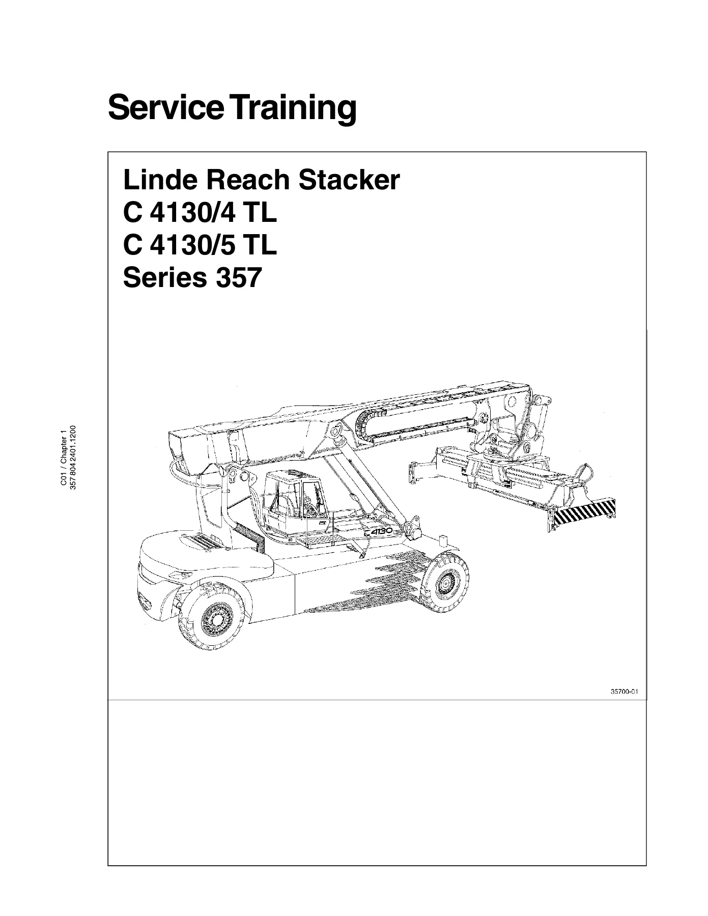
Linde C 4130/4 TL C 4130/5 TL Series 357 Reach Stacker Service Training Manual
Original price was: $39.95.$24.95Current price is: $24.95.
Complete 373-page Linde service training manual for the C 4130/4 TL and C 4130/5 TL Series 357 reach stacker. Covers diesel engine, CLARK 36000 power shift transmission, D 101 drive axle, steering, braking, electrical, hydraulic, boom and spreader systems with specifications, diagnostics and repair procedures.
Description
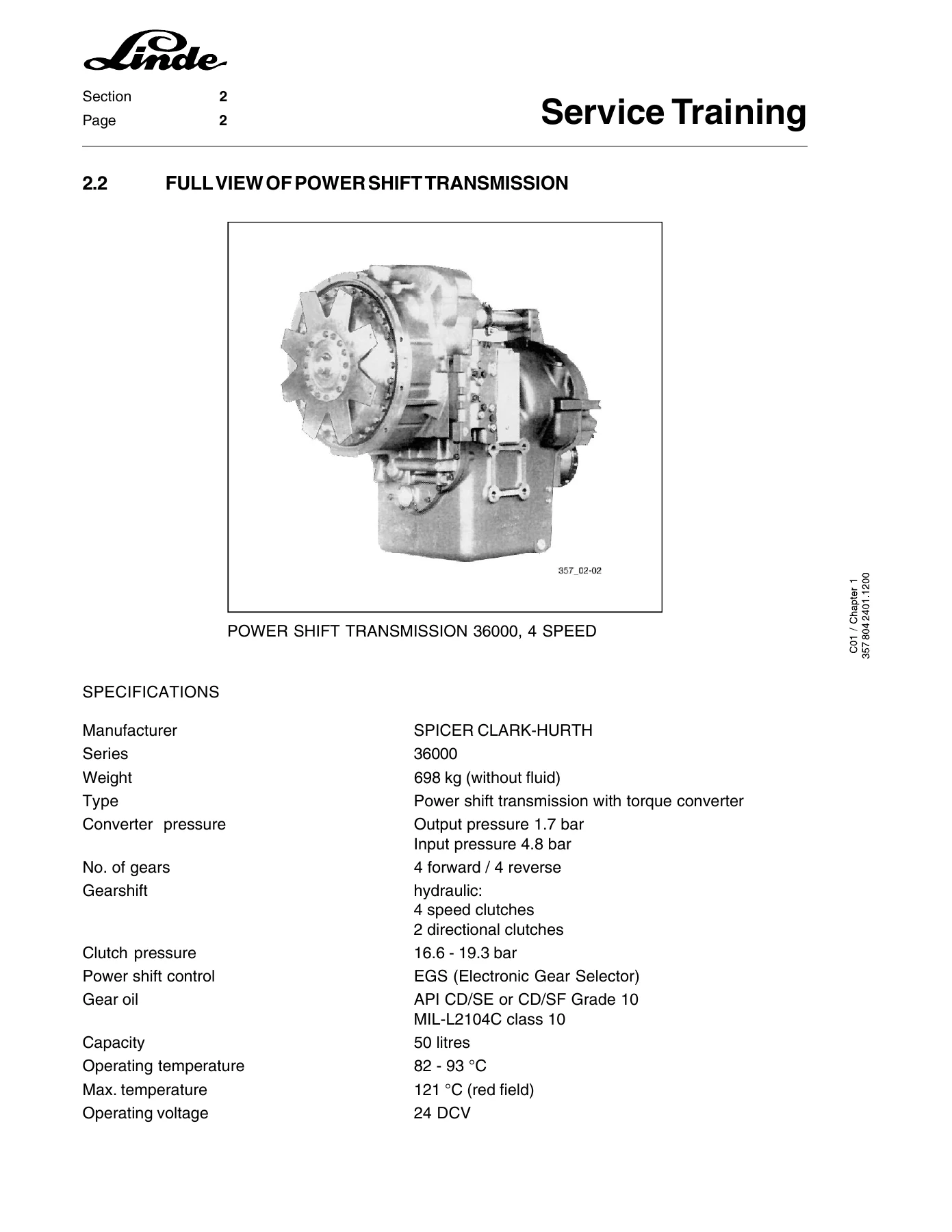
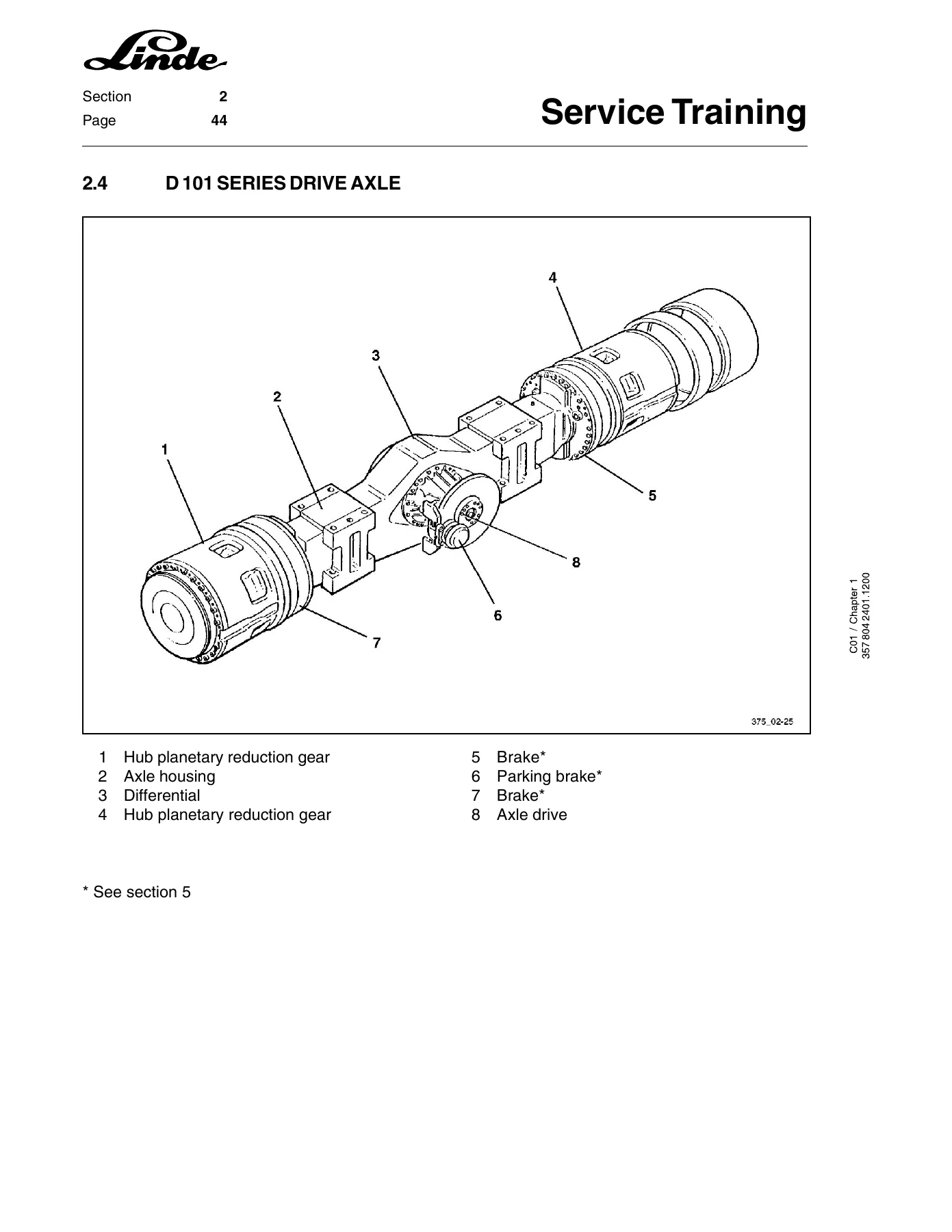
This Linde C 4130/4 TL C 4130/5 TL Series 357 Reach Stacker Service Training Manual is the complete service training documentation used by Linde technicians to maintain, diagnose and repair the Series 357 reach stacker. Covering both the C 4130/4 TL and C 4130/5 TL models, this 373-page PDF gives you the same factory-level procedures, specifications and troubleshooting guidance relied on by professional service personnel. Whether you are servicing the Perkins 2000e diesel engine, rebuilding the CLARK 36000 power shift transmission, adjusting the D 101 drive axle, or diagnosing the programmable computer control system, this Linde reach stacker service training manual provides the step-by-step instructions, torque values and diagnostic detail needed to complete the job correctly.
File Details
- Manual Type: Service Training Manual
- Brand: Linde
- Models Covered: C 4130/4 TL, C 4130/5 TL
- Series: 357
- Language: English
- Page Count: 373
- File Format: PDF
- Document Number: 357 804 2401.1200
Chapters Covered
The Linde C 4130 TL Series 357 service training manual is organised into the following chapters and sub-sections:
- 1. Diesel Engine
- 1.1 Engine Specifications (Perkins 2000e)
- 1.2 Explanation of the Engine Number
- 1.3 Adjusting the Tappet Clearances
- 1.3.1 Checking the Compression
- 1.3.2 Removing and Fitting the Rocker Cover
- 1.4 Drivebelts (alternator, fan, air conditioning)
- 1.5 Cylinder Head (removal, installation)
- 1.7 Checking Engine Timing
- 1.8 Injection Nozzles (fault, removal, installation, correcting, assembly, inspection, opening pressure)
- 1.9 Removing and Installing the Fuel Injection Pump
- 1.10 Fuel Feed Pump
- 1.11 Engine Shutdown Solenoid
- 1.12 Cleaning the Turbocharger Oil Feed
- 1.13 Perkins By-Pass Filter
- 1.14 Thermostat
- 1.15 Coolant Pump
- 1.16 Fault Diagnosis
- 1.17 Torque Loadings
- 1.18 Special Tools
- 2. Hydrodynamic Travel Drive
- 2.1 Schematic Diagram of the Power Train
- 2.2 Full View of Power Shift Transmission
- 2.2.1 36000 Series Power Shift Transmission, 4 Speed
- 2.2.2 Torque Converter (purpose, design, operation)
- 2.2.3 The Power Shift Transmission
- 2.2.3.1 Four Speed Transmission
- 2.2.3.2 Oil Flow in the Power Shift Transmission
- 2.2.3.3 Oil Flow Through the Control Valve
- 2.2.3.4 Transmission Dump System
- 2.2.3.5 Upshift Inhibitor
- 2.3 Troubleshooting (pressure test, measurement aids, CLARK 36000 troubleshooting)
- 2.3.4 Electronic Gear Selector (description, fault diagnosis, inductive sensor adjustment)
- 2.4 D 101 Series Drive Axle
- 2.4.1 Specifications for D 81 PL 478 – NLB
- 2.4.2 Axle Drive Settings
- 2.4.3 Torques for Screws and Nuts
- 2.4.4 Utilisation of Liquid Glue
- 2.4.5 Disassembly or Assembly of Wheels with Clamping Rim Fastener
- 2.4.5.1 Assembly of Hub Differential
- 2.4.5.3 Assembly of the Face Seal
- 2.4.5.8 Installing the Planetary Housing
- 2.4.6 Hub Planetary Reduction Gear
- 2.4.6.1 Repairing the Hub Planetary Reduction Gear
- 2.4.7 Axle Drive
- 2.4.7.1 Installing and Adjusting the Spiral Bevel Gear
- 2.4.7.2 Adjusting the Contact Pattern
- 2.4.7.3 Adjusting the Spiral Bevel Gear Taper Roller Bearing
- 2.4.7.4 Securing the Locknut
- 2.4.7.5 Assembly of Differential
- 2.4.7.6 Assembly of Axle Carrier
- 2.4.7.7 Adjustment of Contact Pattern of Gleason Type Gear Teeth
- 2.4.8 Special Tools
- 3. Truck Body
- 3.1 Chassis Assembly
- 3.2 Cabin (repairing glass pane, window pane, sliding window, roof window)
- 4. Steering System
- 4.1 Steer Axle Type L 101
- 4.2 Steering Hydraulics Circuit Diagram
- 4.3 Description of the Steering Hydraulics
- 4.4 Removing and Installing the Steer Axle
- 4.5 Repairing the Steer Axle (wheel bearings, stub axle, steering cylinder, steering stops)
- 4.6 Special Tools
- 5. Braking System
- 5.1 Braking System Circuit Diagram
- 5.1.1 Description of the Hydraulic Braking System
- 5.1.2 Schematic Diagram of the Braking System
- 5.1.3 Pressure Measurements
- 5.1.4 Accumulator Charging Valve
- 5.2 Construction of the Wet Multiple Disc Brake
- 5.2.1 Checking the Lining Wear
- 5.2.2 Installation of the Piston Cups
- 5.2.3 Installation of the Piston into the Brake Anchor Plate
- 5.2.4 Checking the Air Gap
- 5.2.5 Leakage Test Specification
- 5.2.6 Final Assembly
- 5.2.7 Parking Brake
- 5.2.8 Mechanical Floating Caliper Disc Brake
- 5.2.9 Parking Brake Assembly
- 5.2.10 Replacement of the Brake Pad
- 5.2.11 Instructions for Assembly of the Disc Brake
- 5.3.12 Brake Disc
- 6. Electrical System
- 6.1 Wiring Diagrams (legend, truck wiring diagram, location of boxes)
- 6.2 Programmable Computer Control System
- 6.2.1 Load Safety System Panel
- 6.2.2 Check and Adjustment of the Computer Control
- 6.2.2.1 Safety Precautions
- 6.2.2.2 Table of the “Operative” Menu (software 3.1b and 3.22)
- 6.2.2.3 “Operative” Menu (software version 3.4)
- 6.2.2.4 Output Signal Legend
- 6.2.2.5 Input Signal Legend
- 6.2.2.6 Operation of the Computer System
- 6.2.2.7 Installation Instructions for Potentiometers and Sensors
- 6.2.2.8 Table of Length References for Reach Stacker 4 High and 5 High
- 6.2.2.9 Replacement of a Computer and Necessary Adjustments
- 6.2.2.10 Examples of Computer Programming
- 6.3 Safety Shutoff Relay Box (B7)
- 6.4 Self Test Codes
- 6.5 Additional Information
- 7. Hydraulic System
- 7.1 Legend for Hydraulic Circuit Diagrams
- 7.2 Hydraulic Circuit Diagram (pilot pressure and boost pressure damping)
- 7.3 Working Hydraulics Schematic with Spreader Pilot Pressure Damping
- 7.4 Working Hydraulics Schematic with Spreader Boost Pressure Damping
- 7.5 Pilot Circuit Schematic with Pilot Pressure Damping of Spreader
- 7.6 Pilot Control Circuit Schematic with Spreader Boost Pressure Damping
- 7.7 Functional Description of the Hydraulic System
- 7.8 Functional Description of the Hydraulic Control System
- 7.9 Schematic of Hydraulic System Functions
- 8. Boom and Spreader
- 8.1 Boom (description, removal, assembly, repairs)
- 8.1.4.1 Boom Extension Cylinder
- 8.1.4.2 Lift Cylinder
- 8.1.4.3 Sliding Bearings
- 8.2 Spreader Model 817 (operation, construction, technical data, removal, assembly, repairs, twistlocks, cylinders, slewing gear)
- 8.3 Spreader Model 857 (Piggyback) (operation, construction, technical data, wiring, removal, assembly, repairs)
- 9. Optional Equipment
- 9.1 Automatic Greasing System (functional description, technical data, distribution blocks, grease points, wiring, pump, timer, dispensers, lubricant, malfunctions)
- 9.2 Sliding Cabin (hydraulic circuit, schematic, electrical system, chain tension, traversing speed)
- 9.3 Vertical Lift (circuit diagrams, computer box signals, hydraulic schematics)
- 10. Technical Data
What This Manual Gives You
This Linde Series 357 reach stacker service training manual is far more than a maintenance schedule. It is a full workshop-level training resource that walks through the systems of the C 4130/4 TL and C 4130/5 TL from top to bottom. The diesel engine chapter alone covers tappet clearance adjustment, compression testing, cylinder head removal and installation, engine timing, injection nozzle testing and repair, fuel injection pump timing, thermostat testing, coolant pump overhaul and a full fault diagnosis table. The hydrodynamic travel drive section explains the torque converter, the CLARK 36000 four-speed power shift transmission, oil flow through the control valve in every gear, the electronic gear selector and the D 101 drive axle with detailed adjustment procedures for the spiral bevel gear and Gleason contact pattern. The braking chapter covers the wet multiple disc brake, parking brake, mechanical floating caliper disc brake, pad replacement, air gap checking and leakage testing. The electrical system chapter includes wiring diagrams, the programmable computer control system with menu tables and programming examples, and safety shutoff relay box functions. The hydraulic system chapter provides circuit diagrams, functional descriptions and control system schematics. The boom and spreader chapters cover the boom extension cylinder, lift cylinder, sliding bearings, spreader model 817 and model 857 with their hydraulic and electrical systems. Optional equipment including the automatic greasing system, sliding cabin and vertical lift is also documented.
Every procedure is written with the working technician in mind, including torque values, pressure settings, adjustment dimensions, special tool references and safety notes. The fault diagnosis tables for the engine and transmission help you pinpoint problems quickly rather than guessing. The computer control programming instructions and self-test codes let you diagnose and calibrate the load safety system, and the hydraulic circuit diagrams give you a complete picture of how the pilot and boost pressure systems interact.
Who This Manual Is For
This Linde C 4130 TL Series 357 service training manual is intended for professional technicians, workshop managers, fleet maintenance personnel and equipment owners who need accurate technical information for the C 4130/4 TL and C 4130/5 TL reach stackers. It assumes a working knowledge of diesel engines, hydraulics and electrical systems, and it provides the depth needed to carry out major repairs, not just routine maintenance. If you are responsible for keeping a Series 357 reach stacker running safely and efficiently, this manual gives you the same technical foundation that Linde service training provides.
Get the Complete Linde Series 357 Service Training Manual
With this Linde reach stacker service training manual you can confidently tackle engine overhauls, transmission repairs, axle adjustments, brake servicing, electrical diagnostics, hydraulic troubleshooting, boom and spreader repairs, and optional equipment maintenance. The correct procedures and specifications matter because a reach stacker operates under heavy loads in demanding conditions — using the wrong torque, pressure or adjustment can lead to equipment damage, downtime or safety risks. This manual helps you avoid those mistakes by giving you the values and sequences that Linde specifies.
IMAGES PREVIEW
Delivered as an instant PDF download, there is no shipping and no waiting. The file works on any device — laptop, tablet or smartphone — and you can print the pages you need for the workshop. Whether you are diagnosing a fault on the CLARK 36000 transmission, adjusting the D 101 axle, programming the computer control system or rebuilding a spreader cylinder, this Linde C 4130/4 TL and C 4130/5 TL Series 357 service training manual is the reference you want within reach.
Reviews
There are no reviews yet.