
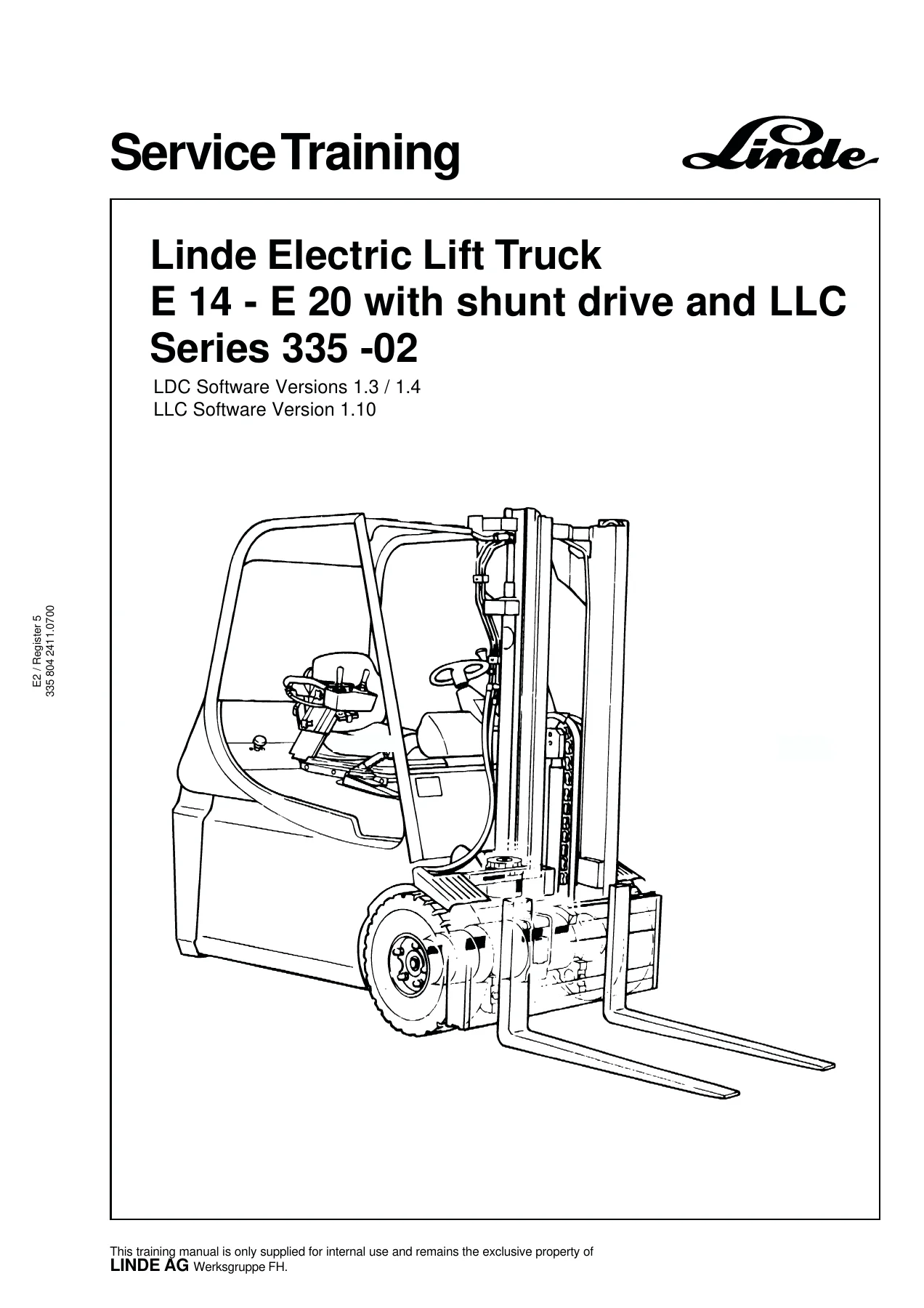
Linde E14 E16 E18 E20 Series 335-02 Forklift Shunt Drive LLC Service Training Manual – PDF
Original price was: $34.95.$19.95Current price is: $19.95.
Linde service training manual for the E14, E16, E18 and E20 (Series 335-02) electric forklifts with shunt-wound drive motors. Covers the LDC traction controller, the LLC working and steering hydraulics controller, both diagnostic window systems with fault code tables, the main current unit, valve blocks, hydraulic plans and optional equipment wiring. 134-page PDF, document 3358042411, dated 07.00.
Description
Linde E14 E16 E18 E20 Series 335-02 Shunt Drive LLC Service Training Manual – PDF
This Linde service training manual covers the E14, E16, E18 and E20 electric forklifts built on the 335-02 series with shunt-wound traction motors and LDC/LLC electronic control. It is a technician training document — the kind used to bring service staff up to speed on the shunt drive electrical system, the Linde Digital Control (LDC) traction controller, the Linde Load Control (LLC) working and steering hydraulics controller, and both diagnostic systems including full fault-code tables. Document number 3358042411, dated 07.00, in English.
Where a standard owner’s book stops at fuses and a maintenance chart, this Linde E14 E16 E18 E20 335-02 training manual goes all the way into the power units, the intermediate circuit, the field and armature control strategy, the joystick signal path, the solenoid valve activation and the internal fault diagnostics. It is the reference a technician needs when a 335-02 truck throws a fault number on the LDC or LLC controller and the shop needs to know what that number means, where the corresponding circuit is and what to do next.
File Details
- Manual type: Service training manual (technician training document)
- Brand: Linde
- Series / models: E14, E16, E18, E20 – Series 335-02
- Drive type: Shunt-wound traction motors with LDC / LLC control
- Document number: 3358042411
- Edition / date: 07.00
- Language: English
- File format: PDF
- Page count: 134
Chapters Covered
- Electrical system
- Control unit for LDC traction drive unit – operating principle, components of the electrical system, control current fuses, positions of the plugs in the truck
- Power units A1 and 1A1
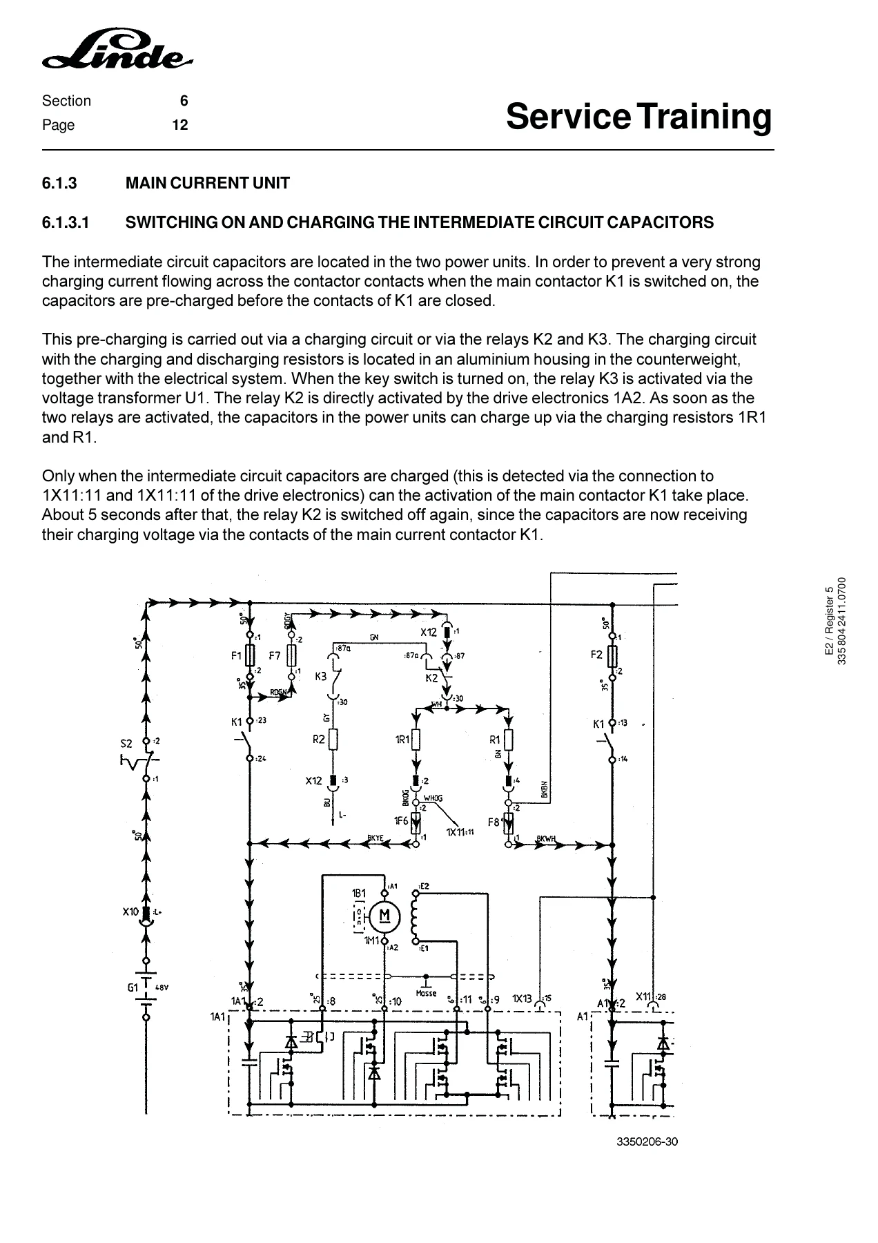
- Main current unit – switching on and charging the intermediate circuit capacitors, discharging the intermediate circuit capacitors, forward and backward direction of travel, free-wheel circuit, regenerative braking
- Control circuit – drive electronics 1A2, power supply, main contactor K1, release signal, accelerator, direction of travel switch (single pedal operation), monitoring the r.p.m. speed of the traction motors, curve signal, emergency off microswitch, temperature signal for the traction motors, hand brake switch, brake pedal switch, discharge relay K2, fans, switch-controlled speed reduction
- LDC (Linde Digital Control) diagnostic system – Window 1 (status information), Window 2 (information and fault messages), Window 3 (stored fault messages), Window 31 (acknowledge faults), Window 32 (delete faults, master only), Window 4 (switch inputs), Window 5 (switch outputs), Window 6 (analog signals), Windows 61/62 (motor analog signals), Window 63 (power unit temperatures), Window 7 (general parameters), Window 71 (default parameters), Window 72 (special parameters), Window 73 (defaults for 7 and 72), Window 74 (UPA designs), Window 8 (neutral pedal programming), Window 81 (steering stops)
- Control system for the working and steering hydraulics of the LLC – control circuit, power supply, release signal, joysticks, activation of the solenoid valves, speed sensor 2B3, monitoring motor temperature and battery charge level, monitoring temperature in the power unit, general monitoring of the power unit
- LLC diagnostic system – Window 1, Window 2 (current information and fault messages), Window 3 (stored faults), Window 31, Window 32, Window 4 (switch inputs), Window 5 (switch outputs), Window 6 (analog signals), Windows 61-64 (joystick signals), Window 7 (parameters for additional hydraulics), Window 71, Window 72, Window 73, Window 8 (general joystick alignment), Window 81 (joystick alignment for additional hydraulics), Window 82 (steering axle selection)
- Circuit diagram
- Additional functions – brake light activation, warning light activation, flashing pilot light activation, operating hours counter while driving and with the pump motor running
- AMP-Saab connector – single wire seal, crimping procedure, extraction pliers, measuring box, adapter cables
- Working hydraulics
- Valve block – single additional hydraulics until 09/98, double additional hydraulics until 09/98, single additional hydraulics from 10/98, double additional hydraulics from 10/98
- Emergency functions, control valve – until 09/98, from 10/98
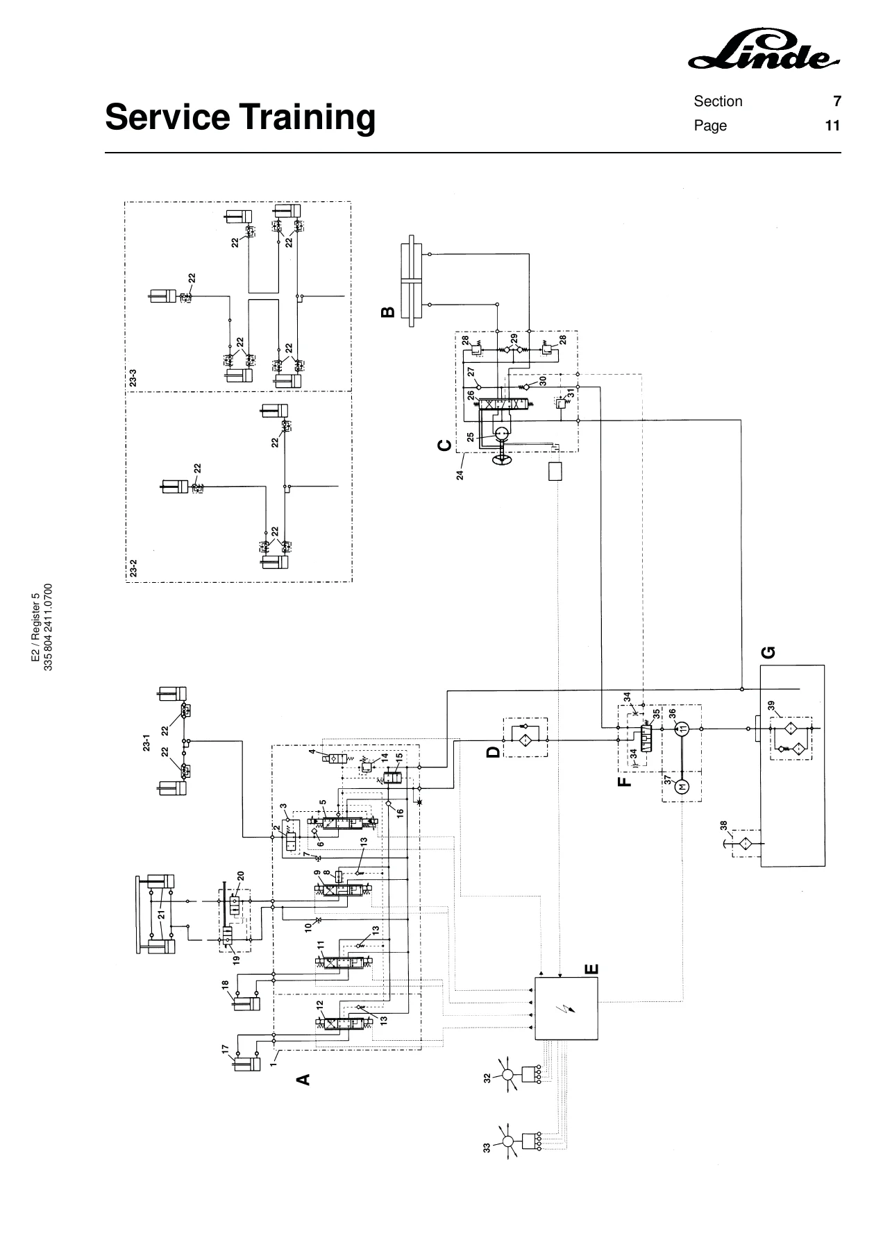
- Hydraulics plan – until 09/98, from 10/98
- Optional equipment series 335-02 – console, voltage converter, fuses, wiring diagram
What This Linde 335-02 Shunt Drive Training Manual Gives You
Series 335-02 trucks are unusual in the Linde electric range because the drive motors are shunt-wound rather than series-wound. That changes the electrical architecture in a meaningful way. This manual explains it from the ground up: how the field winding is controlled through its own power unit rather than being in series with the armature, why the truck can reverse direction without direction-of-travel contactors, how the field current is kept constant at roughly 33 A up to about 6 km/h and then reduced again from about 8 km/h, and how regenerative braking is triggered when the accelerator returns to neutral or the pedal is moved in the opposite direction. The armature voltage vs. speed and field current vs. speed curves are printed in the manual, which makes the control strategy easy to picture.
The LDC and LLC diagnostic chapters are the real heart of the Linde 335-02 shunt drive training manual. Both controllers are covered window by window, with the meaning of each window, what signal it displays, what the normal range is, and — crucially — the fault code tables that map a number on the display back to a probable cause. The LDC table runs the range from the low information numbers up through the traction motor monitoring (right motor numbers 50-59, left motor numbers 60-69) and the internal safety processor numbers 70-99. The LLC table does the same for the working hydraulics: joystick signal faults, safety valve and proportional valve activation faults, speed sensor faults, controller power supply faults, chip temperature faults and so on. Every number in these tables is listed with the observed problem, the fault condition in the controller and the possible causes — plugs, pins, wiring paths, sensors, power units.
The wiring and hardware side is covered just as thoroughly. Plug allocations for the 42-pin drive electronics connectors 1X11 and 1X12, the 29-pin power unit plug X11, the 16-pin plug 1X13, the 42-pin LLC connector 2X11, the joystick connectors, the accelerator 4-pin plug 1X10 and the diagnostic plugs 1X2 and 2X5 — all are broken down by pin with the colour code and function listed. Power unit assembly torque (M10 x 35 hexagon socket screws, 49 Nm, retightened after 30 minutes, thermal paste WP12 on the dissipator surface) is spelled out. Power unit and pump motor fan activation temperatures, motor over-temperature thresholds, and the temperature-related power reductions are given in the control circuit sections.
Working hydraulics is treated separately for two production periods — up to 09/98 and from 10/98 — because the valve block layout and emergency functions changed. Both single and double additional hydraulics versions are shown with the same detailed valve block illustration keyed to the proportional valves 2Y1 through 2Y8, the safety valve 2Y9, the pressure limitation adjustment screw, the max. lowering speed adjustment screw and the emergency lowering screws. Emergency manual mast tilt and manual fork carriage lowering procedures are written out step by step for both periods.
Optional equipment is covered in its own chapter at the end: the console layout, the 250 W and 125 W voltage converters with their LED fault indicators, the fuse assignments for both fuse holders, and the full optional equipment wiring diagram for lights, wipers, rotating beacon, brake lights, indicators and heater.
Who This Manual Is For
This is written for Linde service technicians, workshop foremen, electrical and hydraulic specialists, and fleet maintenance staff responsible for E14, E16, E18 and E20 series 335-02 trucks. It is a training document rather than a flat repair manual, so it teaches the system rather than only listing procedures — which is exactly what makes it useful when a truck has a fault that the parts cannon will not fix. Independent shops servicing Linde electric forklifts of this generation will find the LDC and LLC fault tables, plug pinouts and hydraulic schematics hard to source anywhere else.
Get the Manual and Fix It Right
The Linde E14 E16 E18 E20 335-02 Shunt Drive LLC Service Training Manual gives you the diagnostic language of the truck: what each LDC and LLC window means, what every fault number points to, how the shunt drive is wired, how the hydraulics are laid out, and how the emergency functions work when the truck will not respond normally. Following the correct procedures and using the correct torque, temperature and pressure values matters on a shunt drive machine — wrong field current, wrong temperature reduction or wrong power unit assembly can turn a small fault into a controller replacement.
IMAGES PREVIEW
Delivered as an instant PDF download. No shipping, no waiting. Read it on a laptop, tablet or phone in the workshop, or print the diagnostic tables and wiring pinouts you need for the job in front of you.
Reviews
There are no reviews yet.