
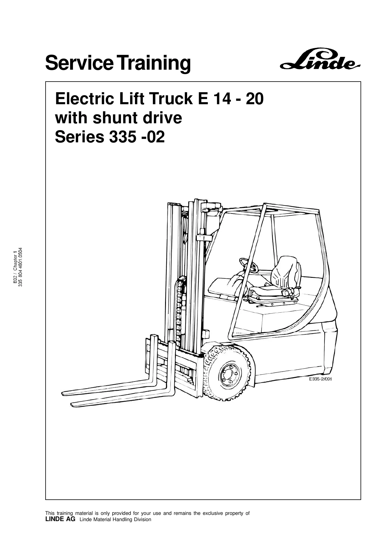
Linde E14 E16 E18 E20 Series 335-02 Shunt Drive Electric Forklift Service Training Manual
Original price was: $39.95.$24.95Current price is: $24.95.
Complete Linde service training manual for the E 14, E 16, E 18 and E 20 electric lift trucks with shunt drive, series 335-02. Covers traction, drive gearbox, steering, controls, electrical equipment, hydraulics, mast unit and special equipment across 306 pages of procedures, wiring and hydraulic diagrams, fault codes and diagnosis windows.
Description
Linde E14 E16 E18 E20 Series 335-02 Shunt Drive Service Training Manual
This Linde E14 E16 E18 E20 Series 335-02 Shunt Drive Service Training Manual is the full service training reference for the 335-02 generation of Linde electric lift trucks fitted with D.C. shunt-wound traction motors. It walks a technician through every major assembly on the truck – from the traction motor brushes and the GR2E-02 planetary wheel gearbox, through the close-coupled and combination steering axles, the brake system and travel controls, all the way to the power units, controllers, working hydraulics, mast unit and optional equipment. Wiring and hydraulic circuit diagrams, diagnostic windows, fault code tables and torque values are all included in the same document, so it works both as a training companion and as a day-to-day workshop reference for the E 14, E 16, E 16C, E 16P, E 18C, E 18P and E 20P trucks.
File Details
- Manual type: Service Training Manual
- Brand: Linde
- Models covered: E 14, E 16, E 16C, E 16P, E 18C, E 18P, E 20P
- Series: 335-02
- Drive type: Shunt drive (D.C. shunt-wound traction motors)
- Language: English
- Page count: 306
- File format: PDF
- Document number: 335 804 4601.0504
Chapters Covered
- 1 Traction – traction motor specifications, right-hand motor 1M1, checking and renewing motor brushes, disassembly, D.C. motor checks, winding measurements, insulation testing, collector reworking, brush switches, thermal sensor, traction motor fan, optional speed sensor, assembly of drive units
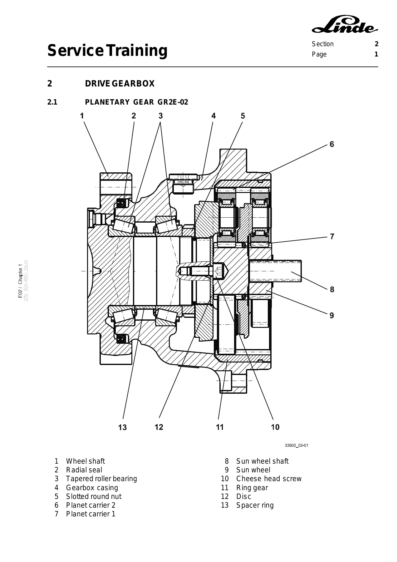
- 2 Drive gearbox – planetary gear GR2E-02, renewing the radial shaft sealing ring, oil level check and oil change, disassembly and assembly of the traction motor
- 3 Chassis and bodywork – seat switch, operator’s cabin, torsion leaf springs, transportation device
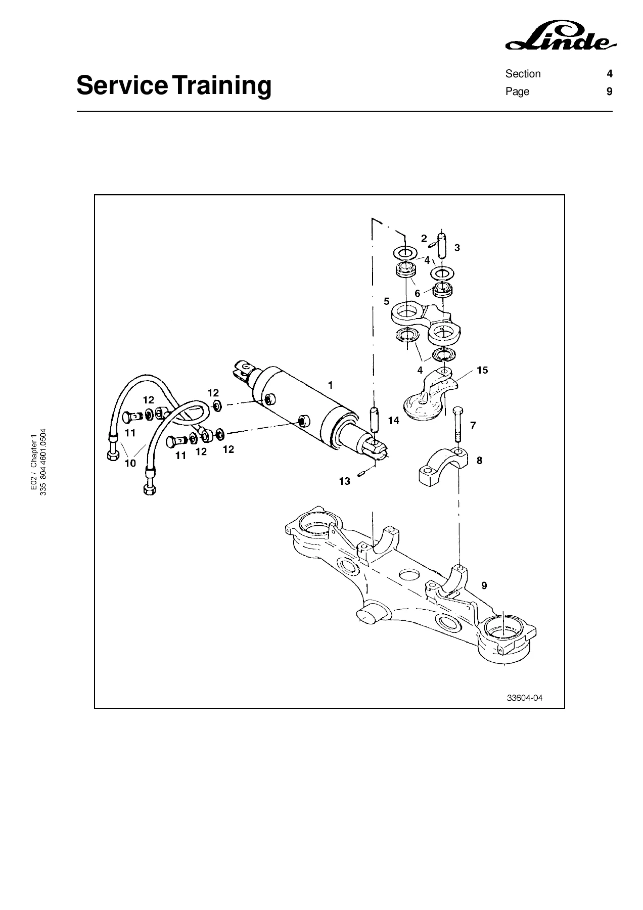
- 4 Steering system – close-coupled steering axle E 14/E 16/E 16C, combination steering axle E 16P/E 18P/E 20P, steering cylinder and track rod link, renewing steering cylinder seals (Rochlitz and Weber), wheel hub tapered roller bearings, axle body bearings and wipers, installing the steering cylinder, Servostat, steering control valve with inductive sensor, renewing the steering position potentiometer
- 5 Controls – truck speed controller, adjustment of pedal stop screws, single-pedal direction switch, braking, renewing brake linings, adjusting the parking brake, adjusting the foot brake, renewing brake fluid
- 6 Electrical equipment – function explanations, traction drive motor control, forward and reverse direction, free-wheel circuit, regenerative braking, pump motor, power units A1 and 1A1, power transistor temperature monitoring, position of connectors, fuses, control circuit individual controllers, control circuit combination controllers, software versions, truck diagnosis windows, fault codes for individual and combination controllers, composite instrument, circuit diagrams, window structure for the controllers
- 7 Hydraulic system – functional description of the working hydraulics, circuit diagram without and with pressure accumulator, emergency lowering functions, control valve, depressurising the working hydraulics, repair work at the valve block, replacing the micro-filter, troubleshooting the control valve
- 8 Mast unit – mounting and dismounting the mast, right-hand lift cylinder with limit position damping, outer and center lift cylinders, sealing the lift cylinder, setting the mast chain, setting roller clearance, sliders, tilt cylinder, setting the tilt angle
- 9 Special equipment – electric special equipment, voltage transformer, fuses, working lights and lighting system, electric heating unit, circuit diagrams
What This Linde 335-02 Service Training Manual Gives a Technician
The manual is built around the Linde 335-02 shunt drive layout, so procedures, pin assignments and torque values match the actual truck instead of a generic electric forklift. Individual and combination controller trucks are separated throughout chapter 6, because the split happened at serial number H2X335N06314 / H2X335N06315 and the wiring, connector layout, fuses and fault codes change accordingly. Later production changes – the inductive steering sensor from H2X335P04374 / H2X335P04653, the four-screw hydraulic pump from H2X335M05432, and the pressure-accumulator valve block from H2X335P04366 – are called out where they affect the procedure.
Fault code sections are split between individual controllers (LDC30C01 / LDC30C02, LLC30C10) and combination controllers (LDC40C00, LDC40C50), with the stored fault numbers, information messages, operator errors, overall fault memory and the windows that display them. This is paired with the diagnostic window structure maps so a technician knows exactly which window to open for switch inputs, switch outputs, analog signals, motor temperatures or calibrations (accelerator pedal neutral position, steering end stops and axle type, joysticks).
Coverage Highlights
- Traction motor data and inspection for the Linde GF116-Q5 D.C. shunt-wound motor – armature 48 V / 105 A, shunt winding 12 V / 17 A, 2000 rpm, 4.0 kW S2 (60 min)
- Winding resistance values (F1-F2 approx. 550 mΩ), insulation resistance ( > 0.5 MΩ), terminal tightening torques (A1/A2 9 Nm, F1/F2 2.5 Nm) and commutator refinishing limits (new 83 mm, minimum 78 mm)
- Planetary wheel gearbox GR2E-02 service – radial shaft seal, gearbox oil SAE 80 W – 90 API GL5, oil change volumes and tightening torques (650 ± 20 Nm for the slotted round nut, 23 Nm for the retaining screw, 64 Nm for the gearbox screws, 195 Nm for the wheel screws)
- Close-coupled steering axle (E 14, E 16, E 16C) and combination steering axle (E 16P, E 18P, E 20P) procedures, including Rochlitz and Weber steering cylinder reseal steps and taper roller bearing settings
- Brake system – renewing brake linings at 2 mm, parking brake and foot brake adjustment, brake fluid renewal interval (3000 operating hours or every 2 years)
- Power unit A1 and 1A1 pin assignments (X11 and 1X13), main-circuit connections, heat conduction paste application, tightening torques
- Working hydraulics – pressure relief valve settings by truck type and mast (180 to 250 +5 bar), pump output 11 cm³/U, micro-filter replacement, depressurising procedure
- Mast unit – lift cylinder sealing, mast chain setting (max. 25 mm extension), roller clearance tables, tilt cylinder sealing and tilt angle values by model
- Electrical and hydraulic circuit diagrams, special equipment schematics and full colour-coded component lists
Who This Manual Is For
Linde-trained technicians, independent forklift workshops and fleet maintenance teams servicing the 335-02 series E 14 to E 20 shunt drive trucks. The depth of the fault code descriptions, the diagnostic window layout and the torque / pressure / clearance tables mean it can be used for both scheduled maintenance and electrical or hydraulic fault-finding. Anyone performing a controller swap, a joystick or steering sensor replacement, a brake reline or a lift mast reseal will find the relevant calibration, torque and adjustment steps here.
Get Instant Access to the Linde E14 E16 E18 E20 Series 335-02 Shunt Drive Service Training Manual
This Linde 335-02 shunt drive service training manual puts the factory training material for the E 14, E 16, E 16C, E 16P, E 18C, E 18P and E 20P trucks straight into your workshop. Use it to diagnose a stubborn controller fault, torque a steering axle bolt to spec, reseal a lift cylinder, set a mast chain or bleed a brake circuit – all without guessing and without waiting for a printed binder to arrive. The PDF is delivered instantly after purchase, opens on any laptop, tablet or phone, and can be printed page by page for use on the shop floor.
IMAGES PREVIEW
Reviews
There are no reviews yet.