
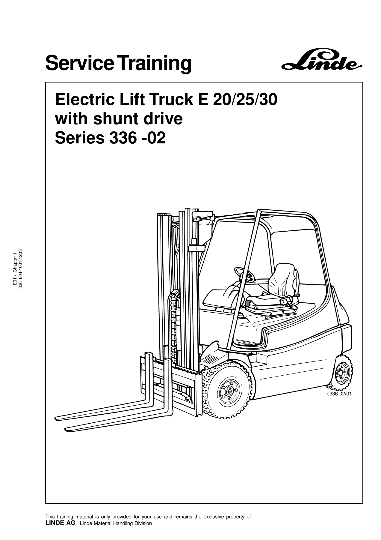
Linde E20 E25 E30 Electric Lift Truck Series 336-02 Service Training Manual – PDF Download
Original price was: $39.95.$24.95Current price is: $24.95.
Linde E20, E25 and E30 electric lift truck service training manual for Series 336-02 with shunt drive. Covers traction motors, planetary gearbox, steering system, controls, electrical equipment, hydraulic system, lift mast and special equipment. English, 310-page PDF.
Description
Linde E20 E25 E30 Series 336-02 Electric Lift Truck Service Training Manual
This Linde E20 E25 E30 electric lift truck service training manual covers the Series 336-02 trucks with shunt drive. It is Chapter 1 of the factory service training material and is written for technicians who service, diagnose and repair the Linde E20, E25 and E30 electric counterbalance trucks. The document walks through the shunt-wound traction motor, the GR3E-03 planetary drive gearbox, the combined steering axle, the travel and braking controls, the full electrical architecture including individual and combination controllers, the working hydraulic system, the lift mast in its standard, duplex and triplex forms, and the electric special equipment. All procedures, tightening torques, resistance values and fault tables are reproduced as printed in the training material.
File Details
- Manual type: Service Training Manual (Chapter 1)
- Brand: Linde
- Model: E20, E25, E30
- Series: 336-02
- Drive type: Shunt drive
- Language: English
- Page count: 310
- File format: PDF
- Document number: 336 804 4601.1203
- Section reference: E01 / Chapter 1
Chapters Covered
- Drive motor
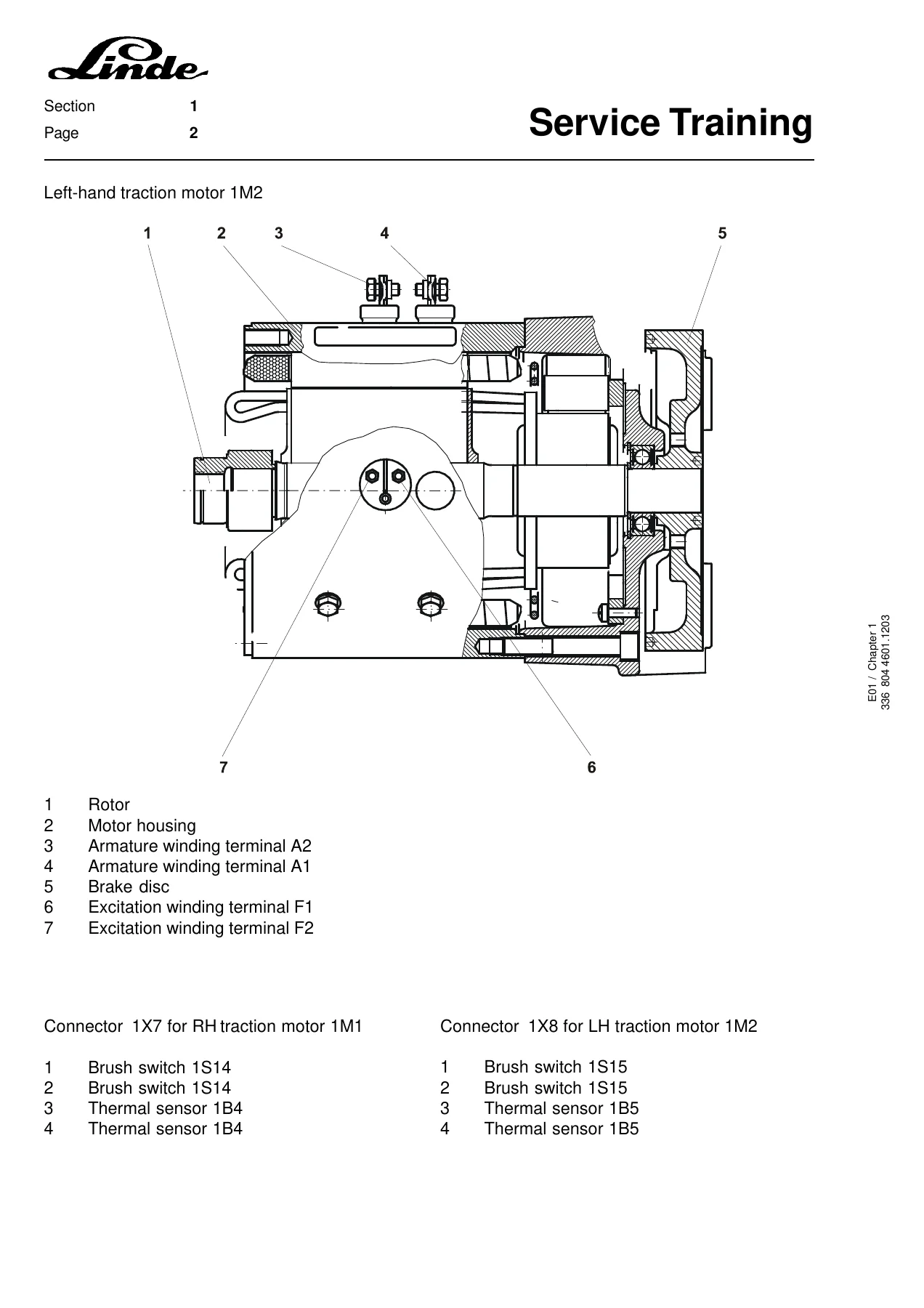
- Traction motor E20 – Linde GF 144-X5
- Traction motor E25/30 – Linde GF 146-X4
- Checking and renewing the traction motor brushes
- Traction motor disassembly
- Checking of the D.C. motor – visual check, operation, winding measurements, insulation, reworking the collector, brush switches, terminals, cleaning, thermal sensor
- Traction motor fan
- Optional speed sensor
- Drive gearbox
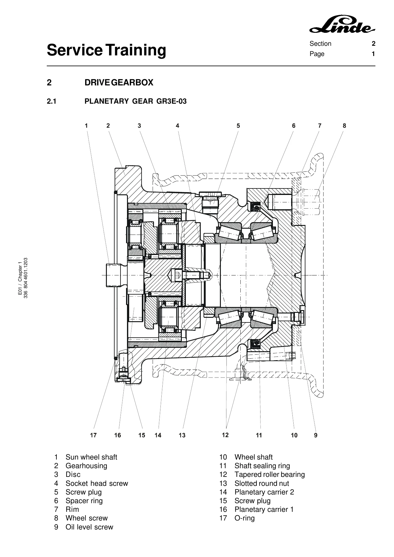
- Planetary gear GR3E-03
- Renewing the radial shaft sealing ring
- Oil level check and oil change
- Disassembly and assembly of the traction motor
- Truck design
- Cabin and weather protection versions
- Torsional leaf springs – assembly, disassembly and setting instructions
- Steering system
- Steering axle removal and installation
- Disassembly of steering cylinder and track rod link
- Renewing steering cylinder seals – E20 and E25/30 Rochlitz type, E20/25/30 Weber type
- Renewing wheel hub and axle body tapered roller bearings and wipers
- Installing steering cylinder and track rod link
- Servostat
- Renewing the steering position potentiometer
- Controls
- Travel control
- Truck speed controller and pedal stop screw adjustment
- Single-pedal direction switch
- Braking – renewing brake linings, adjusting foot brake and hand brake
- Electrical equipment
- Traction drive – principle of operation, forward and reverse direction, free-wheel circuit, regenerative braking
- Power units A1 and 1A1, power unit temperature monitoring
- Position of connectors – individual controllers and combination controllers
- Fuses – control circuit and main circuit
- Control circuit individual controllers – traction controller and working hydraulics controller
- Control circuit combination controllers – pin design of connector X13 and function explanations
- Software versions type 336-02
- Truck diagnosis – traction windows, fault codes for individual and combination controllers, working hydraulics windows and fault codes
- Composite instrument – description, display messages, programming, battery discharge indicator
- Circuit diagrams – individual controller, individual controller panorama version, combination controller
- Window structure for the controllers
- Hydraulic system
- Functional description of the working hydraulics
- Circuit diagram without safety lowering valve
- Circuit diagram with safety lowering valve
- Emergency lowering functions – manual tilting of lift mast and manual lowering of fork carrier
- Control valve – functional description, depressurizing, repair work at the valve block
- Replacing valve cartridges, valve coils and brake valve
- Setting the pressure relief valve
- Replacing the micro-filter
- Troubleshooting control valve
- Lift mast
- Mounting and dismounting the lift mast
- Lift mast Type 186 with limit position damping
- Dismounting and mounting the outer and center lift cylinders
- Sealing the lift cylinder
- Setting of mast chain
- Setting the roller clearance – outer, inner and center mast roller clearance, outer mast clearance
- Sliders – standard, duplex and triplex mast
- Tilt cylinder – dismounting, sealing and setting the tilt angle
- Special equipment
- Electric special equipment – installation positions of working lights, console, converters, fuses, working lights and lighting system, electric heating unit
- Circuit diagram special equipment
- Circuit diagram special equipment switchable
What This Linde Series 336-02 Service Training Manual Gives You
The Linde E20 E25 E30 Series 336-02 service training manual is built around the shunt-wound drive system that separates these trucks from conventional series-motor electric lift trucks. The manual explains how the shunt motor’s field winding and armature winding are controlled independently by the power unit, how travel direction is reversed by reversing the shunt field rather than through direction contactors, and how regenerative braking is achieved without additional contactor hardware. That operational foundation runs through every chapter that follows – from the brush inspection and collector reworking procedures in the motor section, to the MOSFET transistor control and intermediate-circuit capacitor charging in the power units, to the fault code tables that the controller uses to report driver circuit, thermal sensor and intermediate-circuit problems.
On the mechanical side, the training manual works through the GR3E-03 planetary gear in detail: removing the first and second planetary carriers, ungluing the Loctite-secured slotted round nut, pulling the wheel shaft, renewing the radial shaft sealing ring, and refilling the gearbox with SAE 80W-90 API GL5 oil to the correct level. The steering system section covers the combined steering axle used across the E20, E25 and E30, including the two different steering cylinder designs (Rochlitz and Weber) and the specific seal renewal steps for each, plus the axle body tapered roller bearing and wiper renewal procedure with its 1100 Nm retaining screw torque for the E25/30 and 295 Nm dual-screw arrangement for the E20.
The electrical chapters form the largest part of the manual and are where most of the diagnostic value sits. Individual controllers and combination controllers each get their own pin assignment tables, enabling signal descriptions, accelerator and steering sensor calibration procedures, relay driver functions, and truck coding. The fault code chapters break down every information message and fault number for the traction drive and the working hydraulics, with the controller’s trigger condition and the possible causes for each code – covering the LDC33C03, LDC33C04, LDC31C00, LDC31C02, LDC43Drive, LLC33C00, LLC33C01 and LDC43Lift software variants. Circuit diagrams for the individual controller, the individual controller panorama version and the combination controller are included, along with the complete window structure used by the diagnostic software.
The hydraulic section gives a full functional description of the working hydraulics, the circuit diagram in both non-safety-lowering-valve and safety-lowering-valve configurations, the emergency manual lowering and tilting procedures that let a raised load be brought down after a failure, valve block repair instructions for replacing cartridges and coils, pressure relief valve setting values by mast type, and a troubleshooting flow for the most common control valve errors. The lift mast chapter closes with the procedures for mounting and dismounting the mast, sealing the lift cylinder, setting mast chain extension, setting roller clearance for the series 186 and 183 masts, and setting the tilt angle to 5 degrees forward and 7.5 degrees backward.
Who This Manual Is For
This Linde E20 E25 E30 electric lift truck service training manual suits workshop technicians, fleet maintenance teams and independent repair shops working on Series 336-02 shunt-drive trucks. It is also useful for anyone studying the Linde shunt drive architecture, since the training material explains the control philosophy behind the hardware rather than only listing part numbers. The procedures assume access to the truck’s diagnostic software and to standard workshop equipment such as a resistance measuring bridge, insulation measuring unit with 500 V test voltage, torque wrench up to 1300 Nm and the Linde special tools named where required.
Why This Manual Matters for E20, E25 and E30 Repairs
Shunt-drive electric lift trucks behave differently from series-motor trucks in ways that matter during diagnosis. Field weakening changes the relationship between speed and current, regenerative braking feeds current back into the battery, and the controller relies on two potentiometers working in opposite directions to validate the accelerator signal. Without the training material, a technician can easily misread a fault code or adjust a component to the wrong value. The torque figures in this manual – 80 Nm for the 14 gearbox hexagon socket screws, 400 Nm for the wheel screws, 425 Nm for the bearing bracket screws, 195 Nm for the steering axle fastening screws, 1200 Nm for the slotted round nut, 9 Nm for terminal A1 and A2, 2.5 Nm for terminal F1 and F2 – and the electrical values such as the 520-580 milliohm field winding resistance, the 576 ohm thermal sensor resistance at 20 degrees Celsius and the 1.0 plus or minus 0.3 mm speed sensor air gap are exactly the kind of numbers that determine whether a repair lasts. This manual puts them in one place.
IMAGES PREVIEW
Instant PDF Delivery
The Linde E20 E25 E30 Series 336-02 service training manual is delivered as an instant PDF download after payment. There is no shipping, no waiting and no physical media to lose. You can open the file on a workshop PC, a laptop, a tablet or a phone, search through the chapters and fault code tables, and print any page or section you need for the job at hand. Whether you are renewing a steering cylinder seal, chasing a fault 58 on the power unit, setting the pressure relief valve or rebuilding the planetary gearbox, the relevant procedure and specification are in the same document.
Reviews
There are no reviews yet.