
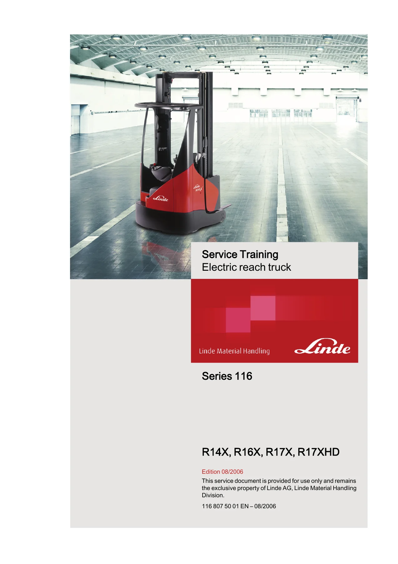
Linde Series 116 R14X R16X R17X R17XHD Electric Reach Truck Service Training Manual
Original price was: $42.95.$26.95Current price is: $26.95.
Linde Series 116 electric reach truck service training manual covering R14X, R16X, R17X and R17XHD models. Complete workshop guidance on traction motor, parking brake, steering, hydraulics, mast systems, CAN bus diagnostics with Pathfinder, error codes and circuit diagrams. Edition 08/2006, document 116 807 50 01 EN.
Description
Linde Series 116 Electric Reach Truck Service Training Manual
This Linde Series 116 R14X R16X R17X R17XHD Electric Reach Truck Service Training Manual is the workshop reference prepared for technicians responsible for the repair and maintenance of the Linde 116 reach truck range. Published by Linde Material Handling under document number 116 807 50 01 EN (Edition 08/2006), it covers the complete mechanical, electrical, hydraulic and diagnostic scope needed to keep these electric reach trucks operating to specification. Whether you are servicing a single R14X or maintaining a fleet of R17XHD trucks, this manual provides the procedures, torque values, diagnostic paths and system explanations a professional needs in one volume.
File Details
- Manual type: Service Training Manual
- Brand: Linde Material Handling
- Series: 116
- Models covered: R14X, R16X, R17X, R17XHD
- Document number: 116 807 50 01 EN
- Edition: 08/2006
- Language: English
- File format: PDF
Chapters Covered
The Linde 116 reach truck service training manual is organised into numbered sections covering every major system on the truck:
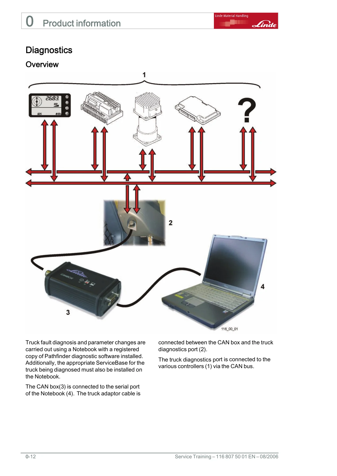
- 0 — Product Information & Safety: maintenance safety guidelines, electrical safety checks, jacking the truck, securing the raised lift carriage, recommended lubricants, special tools and compounds, standard and non-standard torques, diagnostics overview, CAN box, Pathfinder software, error code and parameter page maps, inputs and outputs page maps, traction / hydraulic / steering / display / LAC22 diagnostic codes.
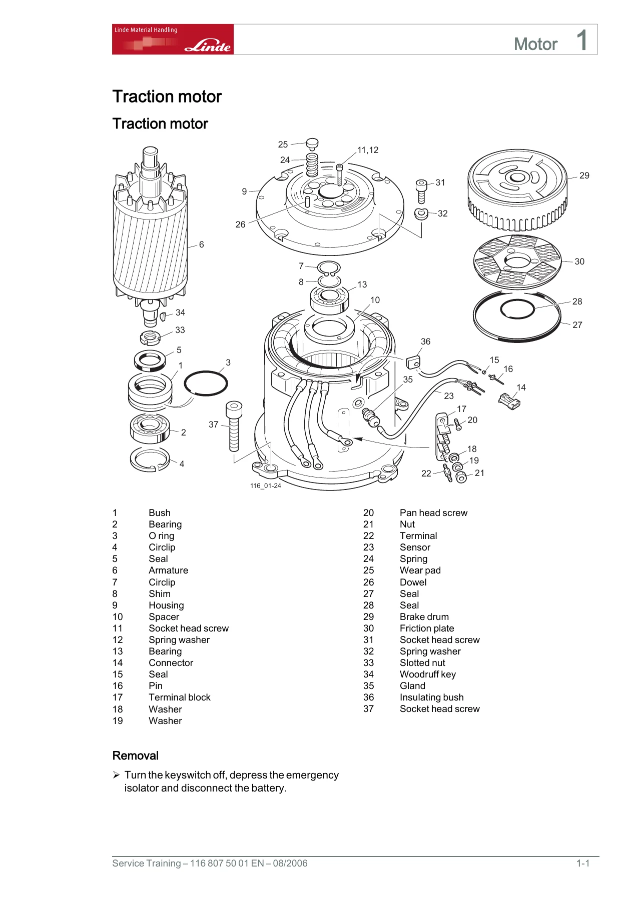
- 1 — Motor: traction motor removal and installation, parking brake adjustment, drum removal and installation, friction plate replacement.
- 2 — Axles: mechanical drive axle, gearbox removal and installation, gearbox mounting plate.
- 3 — Chassis, Bodywork and Fittings: covers and panels, motor/control unit cover, floorplate front and rear sections, operator’s step, front panel, operator’s seat, seat and support plate assembly, storage receptacle, operator’s console.
- 4 — Undercarriage: electrical steering (steering motor, steering wheel and column, steering encoder), wheels and tyres (drive wheel, load wheel), brake installation (hydraulic operated brakes, traction motor brake, load wheel brake, master cylinder, bleeding the brakes).
- 5 — Controls: operating elements, direction switch, right-hand armrest.
- 6 — Electric/Electronic: battery and accessories, battery changing station procedure, battery changing interlocks, electrical control safety precautions, AC control operating principle, connector locations, fuses, emergency isolator, 13 V power supply, control module A2, connector X13 pin designations, power module A1, connector X14, charge resistor module, height encoder and reference sensor, traction enable signal, direction selection switch, parking brake, accelerator, traction motor speed sensor, brake pedal switch, regenerative braking, traction motor temperature sensor, height controlled speed reduction, hydraulic enable signal, valve voltage supply, joysticks, hydraulic pump motor speed sensor and temperature sensor, lower lock valve, primary lift slowdown sensor, lower slowdown and stop sensors, lift and lower electrical operation, reach / sideshift / tilt electrical operation and calibration.
- 7 — Hydraulic Installation: operating hydraulics, hydraulic functions overview, hose cassette, hydraulic motor and pump assembly, joysticks, chassis valve block, carriage valve block.
- 8 — Load Lift System: mast unit (two serial-number variants), mast retainers, mast operation troubleshooting, secondary lift cylinder, reach cylinder, sideshift cylinder, load support, forks, fork carriage, reach carriage.
- 10 — Circuit Diagrams: circuit diagram 116 802 60 11, lighting circuit, hydraulic circuit.
What This Manual Gives the Technician
The Linde 116 electric reach truck service training manual is not a generic overview — it is a procedure-by-procedure workshop document. Each section walks through the correct disassembly, inspection, adjustment and reassembly sequence for the component concerned, with torque figures quoted throughout. The diagnostic chapter shows the technician how to use Pathfinder with the CAN box and truck adaptor cable, how to read the error code and parameter page maps for the traction, hydraulic, steering, display and LAC22 controllers, and how to interpret inputs and outputs for each controller. The result is a document that supports both scheduled maintenance and fault finding on the R14X, R16X, R17X and R17XHD trucks.
Electrical and Diagnostic Coverage
A substantial portion of this manual is dedicated to the electrical and electronic systems that make the Linde 116 what it is. Section 6 explains the operating principle of the AC control system used on the traction and hydraulic motors, including how the six MOSFET bridge synthesises a near-sinusoidal three-phase supply at variable frequency and voltage. It documents the charge resistor module and how the reservoir circuit capacitors are pre-charged before the main contactor closes, the 13 V supplies from converters U1 and U2, the pin-by-pin duties of the 121-way control module connector X13 and the 29-way power module connector X14, and the height encoder and reference sensor used for mast position sensing.
The diagnostics section then ties these systems together with the Pathfinder software. Troubleshooting trees and error code listings are provided for traction, hydraulics, steering, display and LAC22 controllers, split into information codes, warning codes and fault codes according to how they affect the truck. The calibration procedures for the accelerator, reach potentiometer, tilt potentiometer, sideshift potentiometer and lift stages are documented in full, along with the height controlled speed reduction setup.
Hydraulic and Mast Systems
The hydraulic chapters cover the operating hydraulics for lift, lower, reach, sideshift and tilt, including the chassis and carriage valve blocks, the pump 2 dump valve, the lower lock valve, the lower speed select valve and the proportional lower control valve. The manual explains the depressurisation cycle that prevents tilt kick after reach or sideshift operation, and documents the make-up valves fitted to the reach cylinders. Section 8 deals with the load lift system in detail — mast removal and installation for both serial number variants, mast retainer shim checking, troubleshooting for mast bounce, stage transition crashes, mast kick and sticking, plus removal and installation of the secondary lift cylinder, reach cylinder and sideshift cylinder. Fork carriage, reach carriage and fork inspection procedures are all included.
Torque Data and Specifications
Standard and non-standard torque tables are provided in Section 0. Standard metric coarse and fine thread torques are listed from M4 to M36 across grades 4.6 to 12.9. Non-standard torques cover the gearbox mounting plate (700 Nm), load wheel locknut sequence, chassis valve mounting screws, lift pump to motor, primary and secondary cylinder fasteners, chain anchor keep plate, reach roller retaining plate, sideshift rails and support, height encoder covers and more. Drive wheel nuts torque to 195 Nm in a defined sequence, mast securing bolts torque to 650 Nm or 540 Nm depending on the variant, and load wheel axle bolts to 135 Nm — each with the 50-hour recheck requirement noted where applicable.
Safety Content
The manual opens with the safety guidelines a technician must follow before touching the truck: discharging the steering capacitor before working on the control system, isolating the battery before connecting or disconnecting it, checking that the lift carriage locking plate is correctly fitted before entering the battery compartment, and the warnings about working on a raised truck or a raised lift carriage. Additional cautions are embedded throughout the procedures wherever a specific risk exists.
Who This Manual Is For
This Linde Series 116 service training manual is intended for trained and authorised service technicians working on R14X, R16X, R17X and R17XHD electric reach trucks. It assumes prior familiarity with lift truck systems and safe workshop practice. It is a training and reference document rather than a first-time learner’s guide, and it is best used alongside the relevant truck’s User Manual for the full inspection and maintenance schedule.
Why This Manual Matters
Working on electric reach trucks without the correct procedures and torque figures risks damage to safety-critical components and can compromise the stability and braking performance of the truck. The Linde 116 service training manual gives the technician the manufacturer’s own sequences, values and diagnostic logic, so repairs are carried out correctly the first time. Mast alignment tolerances, brake bleeding sequences, charge circuit behaviour, controller pin-outs and calibration routines are all documented — details that are not always obvious from the machine itself.
IMAGES PREVIEW
Instant PDF Delivery
This listing is for a digital PDF copy of the Linde Series 116 R14X R16X R17X R17XHD Electric Reach Truck Service Training Manual. The file is delivered instantly after payment — no shipping, no waiting. It can be viewed on any device that reads PDFs, from a workshop laptop to a tablet on the shop floor, and pages can be printed for use alongside the truck. Bookmark the diagnostic code sections for quick reference during fault finding, or print the torque tables and keep them at the bench.
Reviews
There are no reviews yet.