Linde Electric Lift Truck Series 336 02 Explosion Protected E20 E25 E30 Service Training Manual – PDF DOWNLOAD
Original price was: $36.95.$18.95Current price is: $18.95.
Linde Electric Lift Truck Series 336 02 Explosion Protected E20 E25 E30 Service Training Manual
Description
Linde Electric Lift Truck Series 336 02 Explosion Protected E20 E25 E30 Service Training Manual
FILE DETAILS:
LANGUAGE:ENGLISH
PAGES:118
DOWNLOADABLE:YES
FILE TYPE:PDF
LINDE ELECTRIC LIFT TRUCK SERIES 336 02 EXPLOSION PROTECTED E20 E25 E30 SERVICE TRAINING MANUAL – PDF DOWNLOAD:
IMAGES PREVIEW OF THE MANUAL:
DESCRIPTION:
Linde Electric Lift Truck Series 336 02 Explosion Protected E20 E25 E30 Service Training Manual
GENERAL INFORMATION :
This training course documentation is supplementary to the already existing training manual for the non- explosion-protected version of the electric tmcks of BR 336-02 and contains only those sections which are relevant with regard to explosion protection. For this reason, certain sections are not included in this manual.
INSTRUCTIONS
- All maintenance and repair activities with respect to explosion-protected trucks may only be carried out in areas without potentially explosive atmospheres.
- Explosion-protection measures may never be changed in a way which might affect their function. Changes of the classification with regard to the level of explosion-protection are not allowed either.
- All works must be carried out by qualified, Linde-authorized persons (specialists) who are familiar with the rules and regulations in the field of explosion protection.
- Never change the terminal assignment of the terminal strips. since a different assignment is not allowed. Lighting devices etc. which are installed at a later stage must be connected in keeping with the circuit diagram.
- For all further instructions and rules in this context. please refer to the “Ordinances and Regulations for Linde Explosion-Protected Trucks to Directive 94/ 9/ EC”.
TABLE OF CONTENTS:
Linde Electric Lift Truck Series 336 02 Explosion Protected E20 E25 E30 Service Training Manual
Electric Fork Lift E 20/25/30 Explosion Protected, Series 336—02 Ex
General information
Instructions
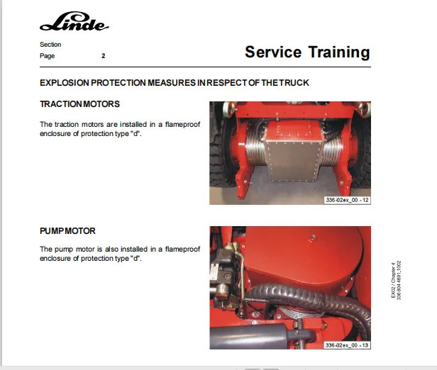
Explosion protection measures in respect of the truck
Traction motors
Pump motor
Battery
Safety measures
Marking
Commissioning
Installation and replacement of batteries
Operation and charging
Maintenance. repair
Environmental conditions
Battery plug—in unit
Design of battery connector
Design of battery coupling
Dismantling of Battery plug-in unit to line connection
Dismantling of battery coupling
Installation of battery coupling
Dismantling the Battery connector
Mounting the Battery connector
Wheels
Electrical Installation
Brake
Fork amis
Indicator instruments
Tightening torques for covers of flameproof enclosures
Special tools
1 Drive – traction motor
1.1 Traction motor
1.1.1 Technical data
1.1.2 General
1.1.3 Checking the carbon brush wear of the traction motors. replacing the carbon brushes
1.1.4 Cleaning of the traction motors
Drive – Gearbox
Removing and installing the drive axle
removing the driving axle and cleaning the traction motors
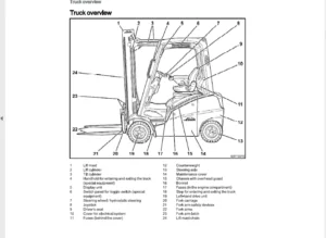
Truck design
Driver seat
Checking the leakage resistance of the driver seat
Steering system and wheels
Servostat
Curve sensor
Driving wheels
Checking the leakage resistance of the driving wheels
Operator’s control ele—ments
Truck speed controller. Replacement of truck speed controller
Electric system
Flameproof enclosures
Maintenance of flameproof enclosures
Control housing Zone 1
Flameproof enclosure for voltage transfomrer Zone 1
Control housing Zone 2
Flameproof enclosure for voltage transformerZone 2
Flameproof enclosure intrinsic safety Zone 2
Checking the PG—glands fortheir sealing effect
Checking the condition and fim1 seat of electric lines
Checking the insulation resistance of the electric system
Procedure I determination of limit values for insulation monitoring in potentially explosive atmospheres
General information
Checking the insulation resistance of the electric system
Intrinsically safe circuits
Switch amplifier-function and description (Design in accordance with 94/9EC)
General circuit diagram of a switch amplifier
Performance test of the switch amplifiers
Replacement of switch amplifiers
Zener barrier. Function and description (designed in accordance with 94/9EC)
Terminal markings of Zener banier
General circuit diagram onener barrier
Checking the internal resistances of the Zener barriers
Voltage supply
Monitoring unit 1V1 and Enable signal
Insulation monitoring (94/9/EC)
Checking the insulation monitoring system 3V3
Circuit diagram of insulation monitoring system
Terminal assignmentx1
Terminal assignment XZ1 transformerhousing—AUX.
Terminal assignment XZ—intrinsic safety
Circuitdiagram
traction control
Voltage transformer, Thermal protection, composite instrument
Lift control
Traction control and insulation monitoring
Lighting and aux. electric system
Schematic drawing of individual components in the flameproof enclosures -Zone 1
Control housing — (top view)
Control housing (side view)
Flameproof enclosure – voltage transformer (Side view)
Flameproof enclosure – voltage transformer (top View)
Working hydraulics
General information
Maintenance and emergency functions of working hydraulics
Manual tilting of the mast
Lowering the fork carrier manually. category 2 G (Zone 1)
Lowering the fork carrier manually. category 3G (Zone 2)
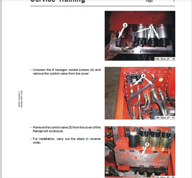
Removal and installation of Hydraulic control valve (Zone 1)
PLEASE NOTE:
- This is the SAME MANUAL used by the dealerships to diagnose your vehicle
- No waiting for couriers / posts as this is a PDF manual and you can download it within 2 minutes time once you make the payment.
- Your payment is all safe and the delivery of the manual is INSTANT – You will be taken to the DOWNLOAD PAGE.
- So have no hesitations whatsoever and write to us about any queries you may have : heydownloadss @gmail.com