
Linde Forklift Truck H series Type 394-02:H40 H45 H50 Service Training Workshop Manual – PDF DOWNLOAD
Original price was: $49.95.$28.95Current price is: $28.95.
Linde Forklift Truck H series Type 394-02:H40 H45 H50 Service Training Workshop Manual
Description
Linde Forklift Truck H series Type 394-02:H40 H45 H50 Service Training Workshop Manual
FILE DETAILS:
LANGUAGE:ENGLISH
PAGES:750+
DOWNLOADABLE:YES
FILE TYPE:PDF
LINDE FORKLIFT TRUCK H SERIES TYPE 394-02:H40 H45 H50 SERVICE TRAINING WORKSHOP MANUAL – PDF DOWNLOAD:
IMAGES PREVIEW OF THE MANUAL:
DESCRIPTION:
Linde Forklift Truck H series Type 394-02:H40 H45 H50 Service Training Workshop Manual
FOREWORD:
The vehicle qualities of economic efficiency and operating comfort are again greatly enhanced in the 394-02 truck series. Application of the MPR ‘adjustable medium-pres- sure pump“ in the woddng hydraulics enables lift— ing, tilting and the auxiliary hydraulic function to be carried outwithjust a slight (load-dependent) increase in engine speed. For example, the truck performs the “lifting“ function at approx. 1200 rpm below the previous model. The LPG engine remains almost unchanged.
TABLE OF CONTENTS:
Linde Forklift Truck H series Type 394-02:H40 H45 H50 Service Training Workshop Manual
0 Product information
Foreword 0-1
Truck 394-02 0-1
Diagnostics 0-4
LHC basic structure 0-4
Consumables 0-9
LPGengine 0-9
Recommendationsfor consumables 0-9
Diesel engine 0-11
Recommendationsfor consumables 0-11
1 Engine
LPG engine 1-1
Description of the drive 1-1
BMFVR6technical data 1-1
Checking the engine power rating in trucks with adjustable hydraulic pump MPR 50 …. 1-2
Checking engine power rating 1-3
Assessing the engine power rating via the engine utilisation 1-3
Setpoint values with tolerance 1-4
Comparison of emission values (in vol. %) 1-4
Engine block 1-5
V-ribbed belt—removal and installation 1-5
Checking the compression pressure 1-6
Cylinder head— removal and installation 1-7
Checking and adjusting the timing 1-14
Removing and refitting the cylinder head cover 1-22
Installing and removing camshafts 1-22
Cooling 1-27
Engine cooling system 1-27
Coolant -draining and filling 1-30
Coolant regulator housing assembly and disassembly 1-32
Engine electrics 1-33
Three-phase alternator 1-33
Electronic ignition system—overview 1-34
LPGsystem 1-36
Safety guidelines for LPG(extract) 1-36
Basic ruleswhen working with LPG 1-37
Sealing plastic pipe unions 1-40
Functions 1-41
LPG system – functions 1-41
Shut-down due to lack of gas 1-43
Service Training -394 801 20 01 EN-01/2013 V
Table of contents
Evaporator -functions 1-44
Mixer -functions 1-46
Default settings for the LPG system 1-47
Speed control (from chassis number H2X394U04459 onwards) 1-49
Shut-off valve -LPG 1-51
LPGtruck with a lambda control system 1-52
Exhaust gases -composition 1-52
Lambda control system 1-53
Leakage test on LPGsystem 1-58
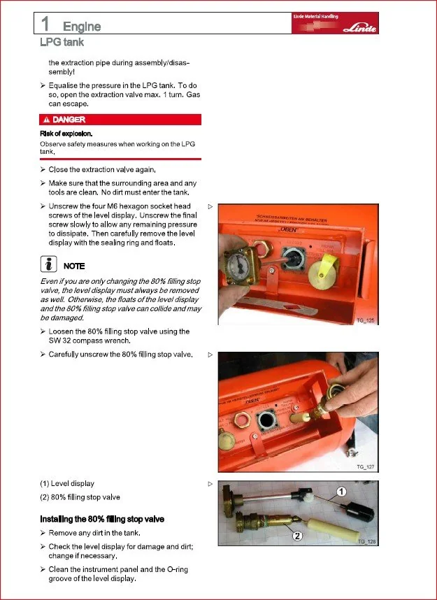
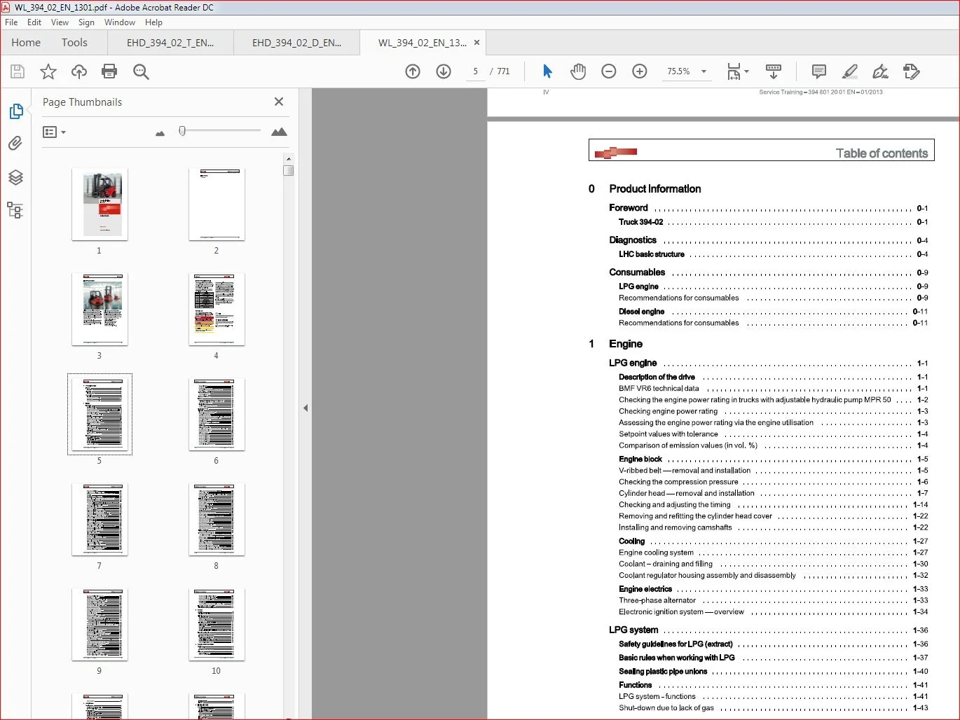
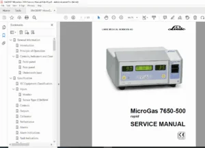
LPGtank 1-61
Removing and installing the level display and 80% filling stop valve 1-61
Level display with single replacement cylinders(special equipment) 1-61
Carrying out assembly operations 1-72
Bleedingthe LPGtank 1-75
The following safety measures must be observed 1-75
Procedure for bleeding 1-76
Diesel engine CPYA/D 1-79
Introduction 1-79
Glossary component designations Linde-VW 1-79
Engine code letters/engine designations 1-80
Technical data CPYA/CPYD 1-81
Checking engine power rating 1-83
Checking the engine power rating in trucks with adjustable hydraulic pump MPR50 . . . 1-83
Assessing the engine power rating via the engine utilisation 1-84
Setpoint values with tolerance 1-84
Sensors -overview 1-85
Pin assignment oftheVW controller with 154 contacts 1-87
Diesel particle filter system 1-92
Self-diagnostics 1-97
Features of self-diagnostics 1-97
Self-diagnostics technical data 1-97
Connect laptop with “Pathfinder” diagnostics program and select control unit 1-98
Connect test adaptor for line test 1-99
Reading out the error memory 1-100
Delete the error memory 1-101
Error code list 1-101
Errorcode: P0016…P0092 1-102
Error code: P0100…P0697 1-103
Errorcode: P100E…P1698 1-113
Errorcode: P2002…P2634 1-117
Errorcode: P33C8…P3325 1-121
Errorcode: U0001…U140A 1-122
Perform actuator test 1-122
Measured value blocks -safety measures 1-126
VI Service Training -394 801 20 01 EN-01/2013
Table of contents
Read measured value blocks 1-126
Evaluate measured value blocks at idle speed 1-127
Evaluating measured value blocks at full load (engine code letter CPYA/D)…….. 1-147
Crank drive 1-150
Dismantling and assembling the engine 1-150
V-ribbed belt drive – assembly overview (with air-conditioning compressor). 1-151
V-ribbed belt – assembly overview (without air-conditioning compressor) 1-153
Removing and installing V-ribbed belts 1-154
Check ribbed belt 1-156
Remove and install tensioner for V-ribbed belt (only engines with air-conditioning com¬
pressor) 1-156
Removing and installing holderfor ancillary equipment 1-157
Toothed belt drive -assembly overview 1-160
Check the toothed belt drive 1-162
Cylinder crankcase – assembly overview 1-163
Remove and install sealing flanges and flywheel 1-164
Sealing flange belt pulley side -assembly overview 1-166
Changing the sealing ring for the crankshaft (belt pulley side) 1-168
Remove and install sealing flange for crankshaft (belt pulley side) 1-171
Sealing flanges and flywheel -assembly overview 1-173
Changing sealing flange for crankshaft -flywheel side- 1-176
Remove and install crankshaft sensor 0B13 1-184
Cylinder head,valve train 1-186
Cylinderhead 1-186
Cylinder head -assembly overview 1-187
Remove and install camshaft sensor 0B11 1-190
Cylinder head cover -assembly overview 1-192
Toothed belt and toothed belt tensioning pulley for camshaft drive: Change: ……. 1-203
Checking the compression pressure 1-211
Removing and installing the cylinder head 1-213
Removing and installing the vacuum pump 1-218
Repairing the valve train 1-220
Valve train -assembly overview 1-221
Valves 1-222
Changing valve stem seals 1-224
Removing and installing the camshaft 1-228
Removing and installing the camshaft sealing ring 1-234
Lubrication 1-236
Parts of the lubricating system 1-236
Oil pump, oil sump -assembly overview 1-237
Removing and installing the oil sump 1-240
Oil filter support, oil cooler and oil pressure switch 1-242
Cooling 1-253
Removing and installing parts of the cooling system 1-253
Parts of the cooling system on the engine side 1-255
Connection diagram for coolant hoses 1-257
Service Training -394 801 20 01 EN-01/2013 VII
Table of contents
Cooling system: Checking frost protection and coolant level 1-258
Draining and filling coolant 1-262
Coolant pump: Change 1-264
Removing and installing 4/2 directional control valve with coolant regulator1-266
Checking the cooling system for leaks 1-268
Check oil cooler for leaks 1-270
Fuel supply 1-272
Removing and installing parts of the fuel supply 1-272
Safety measures when working on the fuel supply 1-273
Sanitation regulations 1-273
Behaviour during incorrect refuelling 1-274
Draining water from the fuel filter 1-277
Changing the fuel filter 1-277
Removing and installing diesel supply pump 0M4 1-278
Check diesel supply pump 0M4 1-280
Charging 1-282
Charge air system with exhaust turbocharger 1-282
Safety measures during work on the charge air system with exhaust turbocharger . . . 1-282
Sanitation regulations 1-283
Exhaust turbocharger with attachment parts – assembly overview 1-283
Remove and install exhaust turbocharger 1-287
Checking charge air system 1-290
Check charge air system for leaks 1-290
Checking boost pressure regulation 1-292
Connection diagram for vacuum hoses 1-294
Check vacuum system 1-295
Checking boost pressure regulator valve 0Y7 1-296
Check boost pressure sensor 0B1 1-297
Checking position transmitter for boost pressure regulator 0B14 1-299
Check exhaust gas temperature sensor 0B7 1-301
Fuel preparation, injection 1-304
Repairing the diesel direct injection system 1-304
Instructionsfor working on the fuel system 1-304
To avoid injuries to persons and/or destruction of the fuel injection and preheating sys¬
tems, please note the following: 1-305
Safety measures when working on the diesel direct injection system 1-306
Sanitation regulations 1-306
Suction pipe with attachment parts- assembly overview 1-307
Fuelsystem 1-310
Fuelsystem -assembly overview 1-312
Correction values for injection units 1-315
Check open injection units (injectors) 1-316
Removing and installing injection unit (Piezo injector) 1-318
Checking the return flow volume from high-pressure regulating valve 0Y5 1-324
Removing and installing high-pressure regulating valve 0Y5 1-325
Removing and installing distributor list pressure sensor CR 0B3 1-327
VIII Service Training -394 801 20 01 EN-01/2013
Table of contents
Removing and installing high-pressure pump 1-329
Filling/bleeding the fuel system 1-332
Testing fuel system for leaks 1-333
Checking pressure control valve in the fuel return line 1-333
Checking high-pressure pump fuel dosage valve 0Y8 1-334
Checking high-pressure regulating valve 0Y5 1-337
Check distributor list pressure sensor CR0B3 1-340
Checking injection valves (cylinder 1…4) 0Y1…0Y4 1-345
Check crankshaft sensor 0B13 1-347
Checking camshaft sensor 0B11 1-349
Check boost pressure sensor 0B1 1-351
Checking coolant temperature sensor 0B10 1-353
Check fuel temperature sensor 0B12 1-356
Check air volumeter 0B6 1-358
Check butterfly valve 0M1 1-360
Checking power supply for engine control unit 1-362
Changing the engine control unit 1-363
Adjusting particle difference pressure sensor 0B2 1-364
Reading out injector quantity adjustment values (IMA-ISA values) and registering them
in the engine control unit 1-364
Adapting diesel direct fuel injection system control unit 0N1 to the position transmitter
for charge pressure plate 0B14 1-365
Adapting diesel direct fuel injection system control unit 0N1 tothe EGRvalve ……. 1-365
Adapting diesel direct fuel injection system control unit 0N1 to butterfly valve 0M1 . . . 1-366
Checking data bus 1-366
Exhaustsystem 1-367
Removing and installing parts of the exhaust system 1-367
Diesel particle filter -assembly overview 1-368
Changing the diesel particle filter: CPYA, CPYB 1-369
Removing and installing exhaust gas temperature sensor 0B7 1-372
Radiator for exhaust gas recirculation -assembly overview 1-374
Checking exhaust gas recirculation 1-375
Checking EGRvalve 0M2 1-375
Checking lambda probe before cat 0B4 1-377
Check heating system for lambda probe Z19 (in component 0B4 lambda probe before
cat) 1-379
Checking exhaust gas temperature sensor after oxi-catOB8 1-380
Checking exhaust gas temperature sensor after DPF 0B9 1-383
Checking particle differential pressure sensor 0B2 1-385
Service diesel particle filter CPYA, CPYB 1-388
Starter motor, power supply, GRA 1-390
Line connectors on the magnet-operated switch 1-390
Starter motor does not turn 1-390
Starter motor turns too slowly and does not crank the engine 1-391
Removing and installing the starter motor 1-392
Three-phase alternator -assembly overview 1-395
Checking three-phase alternator and voltage regulator 1-397
Service Training -394 801 20 01 EN-01/2013 IX
Table of contents
Removing and installing three-phase alternator 1-398
Removing and installing the voltage regulator 1-400
Removing and installing the ribbed V-belt pulley 1-404
Check function of the free-wheel clutch 1-409
Preheating system 1-410
Preheating system 1-410
Removing, installing and checking sheathed-element heater plugs 1-410
Linde engine protection system (LEPS) 1-413
Linde Engine ProtectionSystem (LEPS) 1-413
2 Gearbox
Description 2-1
Technical data for drive unit 2-1
Drive unit 2-2
Travel drive – introduction 2-2
Working hydraulics pump MPR50 2-4
MPR50—general 2-4
MPR50—overview 2-12
Hydraulic adjustment with electronic activation 2-15
Auxiliary brakevalve 2-19
Start of regulation of the pump 2-21
Bypassvalve 2-23
Output unit 2-24
Removing and installing the HPVvariable displacement pumpcoupling flange …… 2-26
Hydraulic truck diagnostics 2-28
Overview and explanations about diagnostics 2-28
HPV 105-02 pressures – measurements 2-33
Checkingthe hydrostatic traction drive 2-34
Sealing the HMF135wheel motor 2-37
Wheel motorHMF135-2, central brake—sealing 2-48
Gearbox GR6H-changing the shaft seal 2-62
3 Chassis, bodywork and fittings
Chassis 3-1
Axle suspension 3-1
Instructionsfor working with gas springs 3-2
Driver’s seat 3-4
Driver’s seat—Isringhausen 3-4
Driver’s seat controls 3-4
x Service Training -394 801 20 01 EN-01/2013
Table of contents
Service instructions 3-5
4 Chassis frame
Steering system 4-1
Steering system -functional description 4-1
Linde Curve Assistant (LCA) 4-3
Steering axle 1603 4-5
Adjusting the steering stop 4-5
Steering axle—removal and installation 4-6
Repairsto the steering axle 4-8
Replacingthe steering cylinder seals 4-10
Functional description 4-12
Devices/toolsfor manual assembly 4-13
Processfor manual removal 4-16
Removingthe steering pivot pin (pressing out using a fixed press) 4-17
Removingthe axle stub from the axle beam 4-18
Assembly process 4-20
Assembling the upper axle stub bearing and wiper 4-21
Assembly—axle stub 4-23
Assembly—lower axle stub bearing wiper 4-25
Assembling (pre-assembling) the steering pivot pin (pressing in using a fixed press) . . 4-26
Assembling the steering pivot pin (pressing in using a fixed press) 4-30
Assembling the lower axle stub bearing/flange cover 4-31
Assembling the steering angle sensor/cover 4-32
Removal/assembly of the wheel hub/wheel bearing 4-35
Brake system 4-38
Brake release valve 4-38
Brake cable pulls -Adjusting 4-43
Checkingthe brake system 4-46
5 Operating devices
Accelerator 5-1
Function 5-1
Replacement 5-2
Stop screws 5-3
Joysticks 5-4
Joystick variants 5-4
Joystick interlock 5-6
Service Training -394 801 2001 EN-01/2013 XI
Table of contents
Functional description 5-8
Exchange 5-9
6 Electrics/electronics
General 6-1
Safety information for the electrical system 6-1
Cleaning the electrical system 6-1
EMC-Electromagnetic compatibility 6-2
CANbus 6-3
CANbus connection assembly X15 6-4
LIN bus 6-6
Electrostatic charging 6-8
Functions 6-9
LHC 20 functional overview 6-9
Actual-value transmitter for speed 1B1 6-10
Accelerator potentiometer 1B2 6-11
1B4hydraulic oil temperature sensor 6-12
Steering angle sensor 1B11 6-12
Brake pedal switches 1S1and S2 6-14
Suction filter vacuum-operated switch S3 6-15
Water trap sensor 1B13 6-16
Single-pedal drive direction switch 1S2 6-17
Tilt angle sensor 2B3 6-18
Seat switch S4 6-20
XII
PLEASE NOTE:
- This is the SAME manual used by the dealers to troubleshoot any faults in your vehicle. This can be yours in 2 minutes after the payment is made.
- Contact us at [email protected] should you have any queries before your purchase or that you need any other service / repair / parts operators manual.
Asa Connor –
I can find most of what I need. Good deal!
Raphael Quinton –
Fast and friendly