
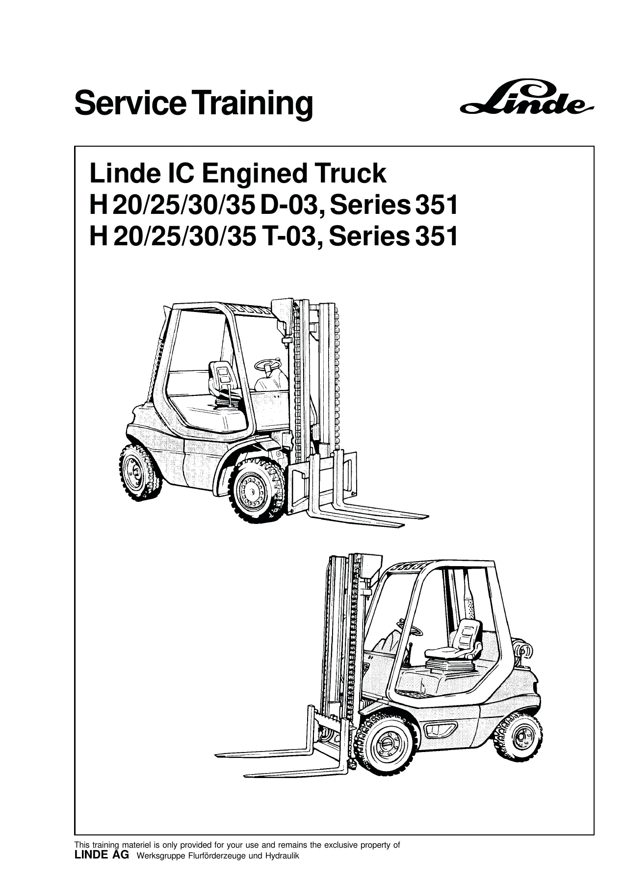
Linde H20 H25 H30 H35 D-03 T-03 Series 351 Service Training Manual
Original price was: $29.95.$17.95Current price is: $17.95.
Complete Linde Series 351 service training manual for H 20/25/30/35 D-03 diesel and H 20/25/30/35 T-03 LPG forklift trucks. Covers engine, hydrostatic drive, hydraulics, steering, electrical, lift mast and LPG systems in 260 pages.
Description
Linde H20 H25 H30 H35 D-03 T-03 Series 351 Service Training Manual
The Linde H20 H25 H30 H35 D-03 T-03 Series 351 Service Training Manual is the technical training document used to prepare service technicians for the complete IC-engined counterbalance truck range built on the Series 351 platform. It covers the diesel-powered H 20 D-03, H 25 D-03, H 30 D-03 and H 35 D-03, plus the LPG-powered H 20 T-03, H 25 T-03, H 30 T-03 and H 35 T-03. Every section moves from a short explanation of how the system works into the actual service procedures, settings, tightening torques and trouble-shooting steps a technician needs on the shop floor.
File Details
- Manual type: Service training manual
- Brand: Linde
- Models covered: H 20/25/30/35 D-03 and H 20/25/30/35 T-03, Series 351
- Engines covered: Perkins 903.27 HR diesel; Renault F3R 262 LPG; Perkins G 903.27 S LPG
- Language: English
- File format: PDF
- Page count: 260 pages
Chapters Covered
- 2.1 Drive — Engine (Diesel): technical engine data, engine serial number layout, valve clearance checking and setting, engine timing gear, V-belt tension checking and tightening, timing gear replacement with tightening torques, cylinder head dismantling and mounting, injection nozzles (clamp and clamping nut versions), injection pump removal and installation (setscrew timing and pin timing versions), fixing angle setting, cold start advance (CSA), fuel supply pump, cooling water system bleeding, special tools
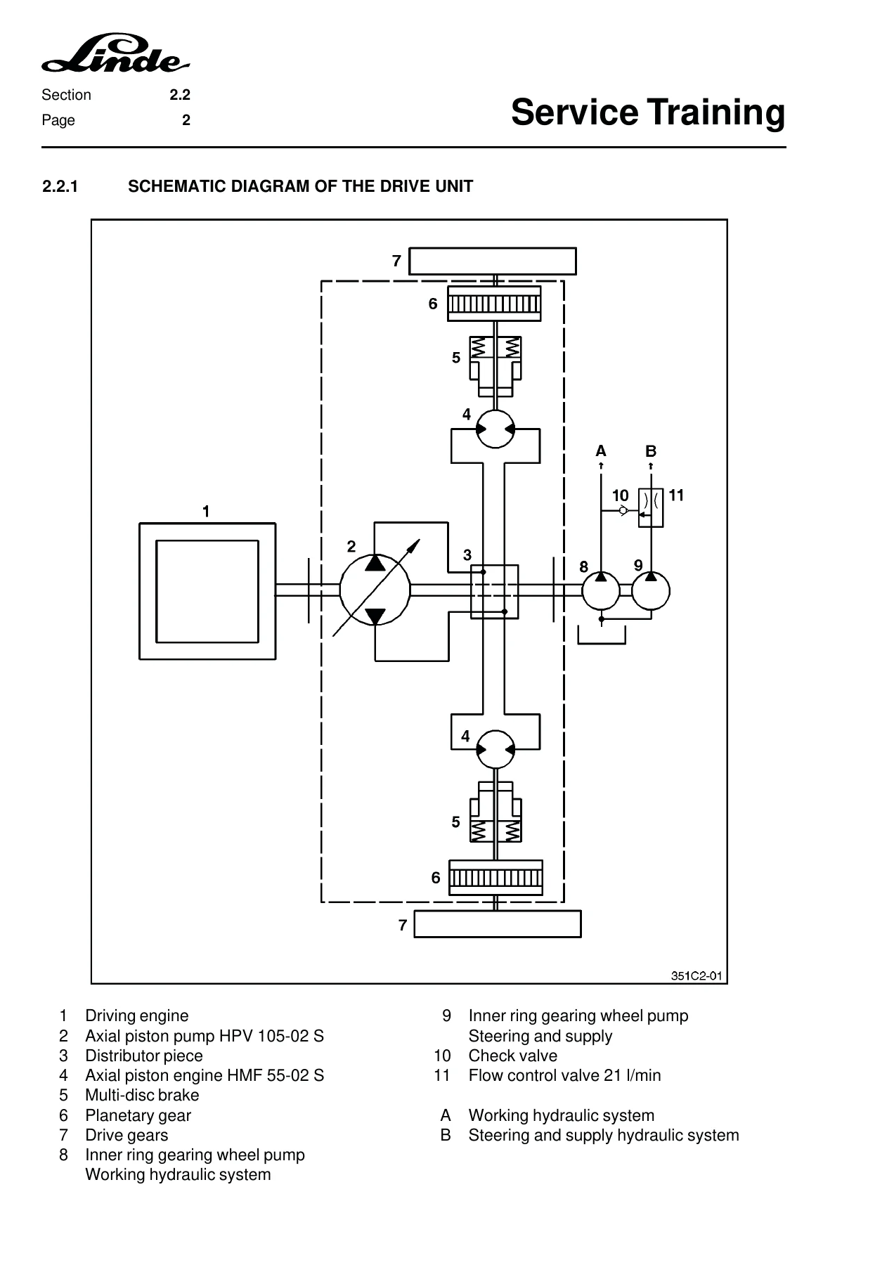
- 2.2 Hydrostatic Drive: drive unit schematic, compact axle type AK 30-02 technical data, hydraulic connection diagram, full hydrostatic drive explanation, axle centre casing flushing, engine output limitation and anti-stalling safeguard, reversing lock of the diesel engine, overrun braking system, oil tank pre-load, hydraulic control M1F settings (reversing lock, hydraulic zero position, pressure difference, brake shaft stop screw, start of rotation, symmetry of the drive transmitter), towing device with grease nipples and short-circuit slide, final drive, reduction gear with multi-disc brake repair, trouble-shooting line diagram and measurement tools
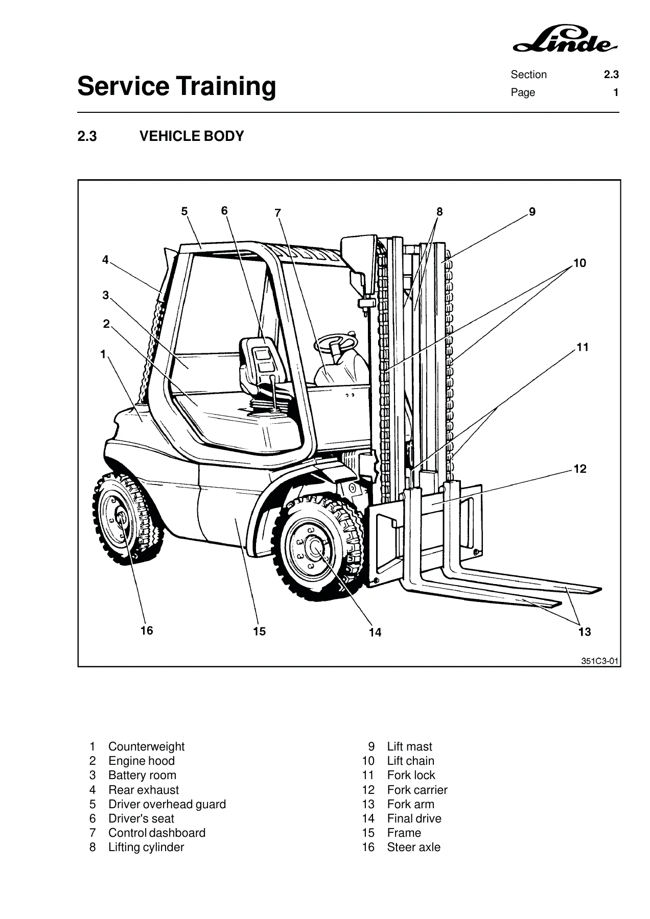
- 2.3 Vehicle Body: display and control elements
- 2.4 Steering Hydraulics: steering hydraulics explanation, steering axle description and axle number, disassembling and installing the steering axle, steering cylinder disassembly and installation, steering cylinder gasket renewal, steering stub axle, wheel bearing replacement, steering lock setting
- 2.5 Controls: speed adjustment instructions, accelerator pedal adjustment for welded and light-metal pedal rocker versions, brake pedal adjustment, Bowden cable for parking brake
- 2.6 Electrical Power System: wiring diagram standard equipment, wiring diagram with auxiliary relay K3, special equipment wiring diagram, display device function and malfunction chart
- 2.7 Working Hydraulic System: connection diagram, system explanation, control valve sealing, pressure-limiting valve setting, tilt cylinder removal and installation, tilt cylinder sealing, side tilt angle setting
- 2.8 Lift Mast: standard, duplex and triplex lift mast types 183/186, disassembling and mounting the lift mast, lifting cylinders with final position damping, outer and middle lifting cylinder removal and installation, lifting cylinder sealing, chain adjustment, roller clearance setting
- 2.9 LPG Trucks: Renault F3R 262 engine (specifications, serial number, valve clearance and shim renewal, engine timing, toothed belt removal and installation, timing gear renewal, cylinder head removal and installation, radial seal removal, electronic ignition system and trouble-shooting, circuit diagram, LPG system schematic and operation, vaporiser and mixer operation, electronic speed control checks and trouble-shooting); Perkins G 903.27 S engine (specifications, serial number, valve clearance, engine timing gear, V-belt, cylinder head, electronic ignition, basic and auxiliary wiring diagrams, LPG system and mixer, electronic speed control, transistorised ignition trouble-shooting)
What This Manual Gives a Technician
This is not a generic overview. It is a working document structured the way a technician diagnoses a fault: measure the pressure, compare against the set value, adjust the shim or screw, retest. The hydrostatic drive chapter, for example, walks through every control pressure and differential pressure value in the M1F control unit — regulation start at 4 bar, pressure difference Y to Z of 10 to 11 bar, supply pressure of 17.5 bar — with the exact adjustment shims, lock nuts and stop screws to correct each one. The engine chapters carry the same level of detail for both the diesel and the LPG side, including valve clearance figures, timing gear tightening torques, cylinder head bolt sequences and injection nozzle pressures.
Trouble-shooting is treated as a first-class subject rather than an afterthought. Flow-chart style diagnosis is provided for the hydraulic speed adjustment, the hydraulic brake system, power-assisted steering, equal pressure and control start, and the hydrostatic travel drive. Each chart branches on measured pressure values and points to the specific valve, nozzle, spring or seal that needs attention.
Diesel and LPG Engine Coverage
The diesel side of the manual is built around the Perkins 903.27 HR three-cylinder engine. It lists the technical data — 2,700 cm3 displacement, 38.4 kW at 2,100 rpm for the H 20/25/30 and 39.5 kW at 2,250 rpm for the H 35, injection nozzle pressure of 300 bar, compression ratio of 17.5:1, valve clearances of 0.20 mm intake and 0.45 mm exhaust — and then takes the reader through the service procedures that depend on those values. Injection pump removal and installation is documented for both the setscrew timing version and the pin timing version, including the fixing angle check with the universal adjusting device and the timing pin procedure with the pump gear.
The LPG side covers two engines: the Renault F3R 262 four-cylinder and the Perkins G 903.27 S three-cylinder. Both get the same treatment — engine specifications, valve clearance adjustment with shim renewal, toothed belt or timing gear service, cylinder head removal and installation with the correct bolt tightening sequence, radial seal renewal, and the electronic ignition system with its own trouble-shooting flow chart. The LPG system itself is covered in depth, including the vaporiser two-stage regulation, the mixer operation, idle and full-load mixture adjustment, and the CO content adjustment procedure.
Electrical and Hydraulic Diagrams
Wiring diagrams are included for standard equipment, for trucks with auxiliary relay K3, and for special equipment options. Hydraulic connection diagrams are provided for the hydrostatic drive, the working hydraulic system and the steering circuit, with numbered component call-outs that match the text. Exploded views and cross-sections show the final drive, reduction gear, multi-disc brake, steering axle, steering cylinder, tilt cylinder and lift mast cylinders in enough detail to support a rebuild.
Why This Manual Matters
Linde Series 351 trucks use a hydrostatic drive with load-controlled pump adjustment and a reversing lock that depends on exact control pressures. Guessing at these settings produces a truck that creeps in neutral, stalls under load, or refuses to build speed after a direction change. The manual gives the actual set values and the adjustment points, so the work can be done once and checked against a measurable result. The same applies to the lift mast roller clearances, the steering lock stop screws, the brake shaft stop screw and the LPG mixture screws — all of them have documented settings that this document supplies.
IMAGES PREVIEW
Instant PDF Delivery
The Linde H20 H25 H30 H35 D-03 T-03 Series 351 Service Training Manual is delivered as a PDF immediately after payment. There is no shipping, no waiting for a physical book, and no risk of a missing page. The file opens on any device — laptop, tablet or phone — and can be printed for the workshop. Technicians working on the diesel Perkins, the Renault LPG engine, the Perkins LPG engine, the hydrostatic compact axle AK 30-02, the M1F hydraulic control, the steering axle or the 183/186 lift mast will find the settings, procedures and trouble-shooting logic they need in one place.
Reviews
There are no reviews yet.