
LiuGong CLG414 Motor Grader Parts Manual 35F0052 – Illustrated Parts Catalog PDF
Original price was: $44.95.$29.95Current price is: $29.95.
Complete LiuGong CLG414 motor grader parts manual, document 35F0052. 328-page PDF with exploded views, part numbers, quantities, service codes and interchangeability notes for all six machine configurations.
Description
LiuGong CLG414 Motor Grader Parts Manual 35F0052
This LiuGong CLG414 Motor Grader Parts Manual (document number 35F0052) is the complete illustrated parts catalog for the CLG414 motor grader, delivered as a 328-page PDF. Every component group is laid out with exploded diagrams, itemized parts lists, LiuGong part numbers, quantities per machine, service codes and interchangeability notes, so parts can be identified and ordered correctly the first time. The manual covers all six CLG414 build codes from 35F00520001B001 through 35F00520001B006, with separate parts listings for the Cummins BSII and BSIII engine variants and the scarifier, ripper and front dozer attachment packages.
File Details
- Manual type: Illustrated Parts Manual
- Brand and model: LiuGong CLG414 Motor Grader
- Document number: 35F0052
- Language: English
- Page count: 328 pages
- File format: PDF
- Configurations covered: Six CLG414 build codes, 35F00520001B001 to 35F00520001B006
- Engine suppliers referenced: Cummins BSII and Cummins BSIII
Configurations Covered by This CLG414 Parts Catalog
The opening pages list the six CLG414 machine configurations this parts manual is indexed against. Because attachments change the parts required at the front frame, work implement, hydraulic and counterweight areas, each configuration has its own component map:
- 35F00520001B001 – CLG414 with Cummins BSII engine, ZF transmission, Xuzhou Meterior axle, AC, G2 tyres, bearing circle (base build)
- 35F00520001B002 – Cummins BSIII engine, scarifier and ripper, bearing circle
- 35F00520001B003 – Cummins BSIII engine, front dozer and ripper, bearing circle
- 35F00520001B004 – Cummins BSIII engine, scarifier, bearing circle
- 35F00520001B005 – Cummins BSIII engine, front dozer, bearing circle
- 35F00520001B006 – Cummins BSIII engine, ripper, bearing circle, counterweight fitted
Chapters Covered
- Fuel Tank AS
- Engine System
- Hydraulic System
- Power Train System
- Brake System
- Structure
- Cab
- Engine Hood
- Electrical System
- Air Conditioning System
- Machine Accessories
- Schematic
Fuel Tank Assembly
Two variants of the Fuel Tank AS are shown: the 00E0870_003_00 outer assembly and the 00E0870X0T0_000_00 detailed breakdown. Exploded views itemize the flange cover, O-rings, bolt, plug, tank cover assembly, snap ring, dipstick, strainer and mounting fasteners, with a step-by-step diagram plus a parts list keyed by item number, part number, service code, quantity and specification.
Engine System
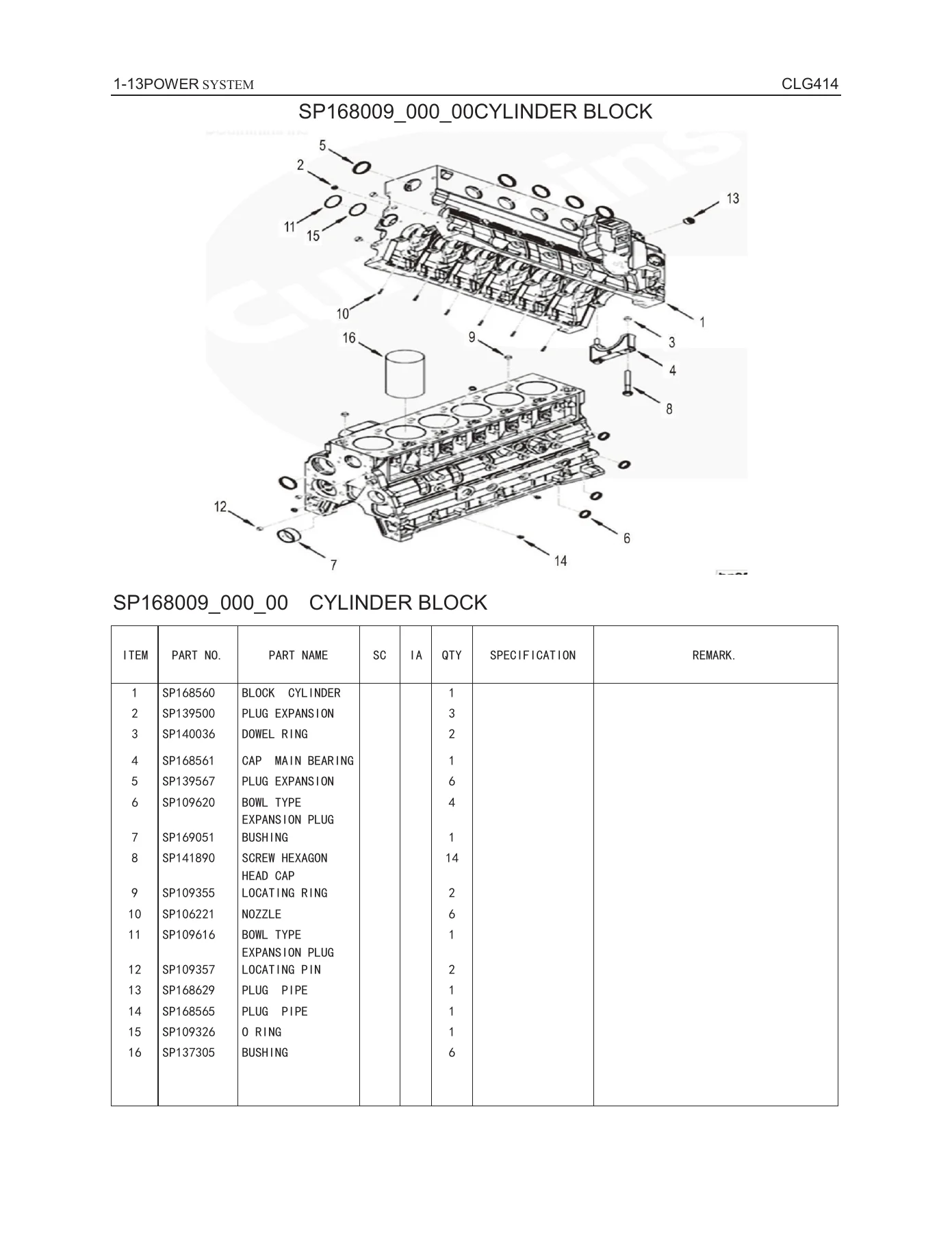
The Engine System chapter opens with the accelerator controller and then moves to the Cummins diesel engine. Portions are reproduced under license from Cummins, and the parts lists reflect Cummins part numbers throughout. Detailed sub-assemblies cover the air intake heater, air fuel control plumbing, turbocharger outlet connections, intake manifold, alternator and drive, cylinder block, fuel shutoff valve, cam follower cover, camshaft, engine oil cooler, fuel pump coupling, front gear cover, crankshaft and bearings, cylinder head, fan drive, exhaust manifold, fuel filter and plumbing, fuel injection pump, oil pan, rocker lever, thermostat, torque converter oil cooler, turbocharger and plumbing, valve cover, valve tappets and vibration damper. The chapter also includes the intake and exhaust system with air cleaner housing, and the cooling system with radiator group and cover.
Hydraulic System
This is the largest chapter in the parts manual. It covers the attachment-specific hydraulic lines first: Ripper Lines (00C1330), Dozer Lines (00C1331) and Scarifier Lines (00C1713), each with its own hose assemblies, hydraulic locks and cylinder. The Steering Hydraulic System is broken down into two assemblies with hose, clamp, front wheel steering cylinder, steering cylinder, ball joint, priority valve, steering column and metering pump. The Work Hydraulic System then unfolds across eight sub-assemblies, covering the pump assembly, working pump, front wheel tilt cylinder, blade sideshift cylinder, blade lift cylinder, piston rod, circle sideshift cylinder, blade pitch cylinder and steering cylinder. Individual control valves, spool sections, hydraulic oil tank, hydraulic locks, swivel joints and the operator platform round out the chapter. Every hose, fitting, cylinder and valve is linked back to the machine drawing by item number.
Power Train System
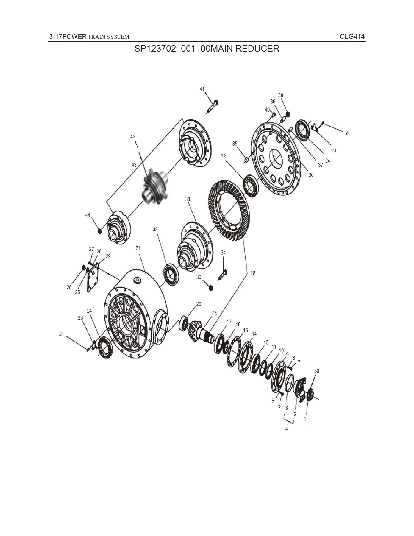
The Power Train System chapter lists the front axle in three parts, followed by linkage, drawbar, shim packs and the front wheel hub. The rear axle group covers piping, main reducer, brake assembly, planetary assembly, balance-box assemblies and the rear drive shaft. The ZF gearbox and torque converter assembly is then broken down in detail: control valve, reducing valve assembly, input device, output, power take-offs, inductive transmitters, emergency steering pump, parking brake, shift system, filler nozzle, transmission housing, converter, layshaft and multiple couplings. Torque converter oil lines, filter lines, tyre and rim assemblies and tyre group complete the section.
Brake System
A compact but complete chapter covering the brake hose, charge valve assembly, charge valve, brake valve assembly and the sign group used at the brake valve location.
Structure
The Structure chapter handles the load-bearing and attachment hardware: front frame assembly, swing arm, fork, plate assembly, rear frame assembly, battery boxes (LH and RH), articulated hitch, ripper, cover and tooth, scarifier (two sub-assemblies), blade, work implement system, worm box, adjusting gaskets, shim packs, blade assembly, work implement skeleton, dust covers and counterweight.
Cab
Cab assembly and its sub-assemblies, bracket, guard, control box and control box assembly, LH and RH doors, door locks, rearview mirror, seat, and shock absorber. The cab chapter is useful for anyone replacing trim, glass, locks or the seat.
Engine Hood and Ladder
Ladder assembly and the engine hood assembly are listed together as the access hardware for daily checks and service on the engine deck.
Electrical System
Front frame wiring and cab wiring are the two main harness groups, each broken into individual harnesses, contactor harness and fuse board. Battery wiring, positive and negative cables, disconnect switch and rear frame wiring follow. Lighting covers floodlights, front and rear position lights, dome light, licence light and front floodlight. The wiper system, sound wiring and radio/cassette player are also covered, plus the work light wiring harnesses.
Air Conditioning System
Water hose, refrigerant receiver assembly, evaporator assembly, compressor mounting and mounting plate are itemized for the cab HVAC system.
Machine Accessories and Schematics
The label system (two sub-assemblies), decal group, reflector, spare parts list, oil specification list, anti-freeze and tool kit are listed here. The chapter closes with the hydraulic schematic (15E0483) and the electrical schematic (50Y0252).
How the Parts Lists Are Structured
Every assembly follows the same convention. The title line gives the assembly part number, version and name; the exploded drawing uses numbered callouts; and the table below lists item, part number, part name, service code, interchangeability code, quantity and specification. Service codes tell you whether a part is sellable: A (not for sale), B (repair through upper parts), C (repair through sub-parts), D (not sold separately), E (superseded by a new part number), F (see remark), G (only sold as an assembly) and Z (has sub-parts). Interchangeability codes tell you whether the part before and after a change can be swapped: Y (two-way replaceable), N (not replaceable), I (one-way, new replaces old), P (do not use old part), with TY/TN/TI/TP for group-level interchangeability. That metadata is exactly what a parts counter needs to avoid returning the wrong component.
Why This LiuGong CLG414 Parts Manual Matters
Motor grader repairs fail for one of two reasons: the wrong part number gets ordered, or the correct part arrives but the wrong fastener or seal pack is fitted alongside it. This catalog removes both problems. You can look up an assembly by name, trace the exact part number, confirm the quantity per machine, and check the interchangeability code before the order goes out. For a CLG414 that is running Cummins BSIII with a scarifier, for example, the manual tells you precisely which hydraulic lines and cylinders apply to that build, and which do not. That saves ordering errors, downtime and freight costs.
IMAGES PREVIEW
Instant PDF Delivery
The LiuGong CLG414 Motor Grader Parts Manual 35F0052 is delivered as a printable PDF. There is no shipping, no waiting for a disc, and no courier. Open it on a workshop tablet, a laptop at the parts counter, or a desktop in the office, and print whichever exploded view you need. Whether you are rebuilding a blade lift cylinder, tracing a wiring harness through the cab, or simply looking up the correct part number for a fuel tank flange cover, this CLG414 parts catalog gives you the illustrated answer in one searchable file.

Reviews
There are no reviews yet.