
LiuGong CLG766A CLG777A Backhoe Loader Service Repair Manual PDF
Original price was: $39.95.$24.95Current price is: $24.95.
Complete 518-page service manual for LiuGong CLG766A and CLG777A backhoe loaders, covering maintenance, hydraulic testing and repairs, steering, brakes, electrical troubleshooting, A/C, engine-related procedures, power train, and major component removal and installation.
Description
LiuGong CLG766A CLG777A Backhoe Loader Service Repair Manual PDF
This 518-page service manual covers the CLG766A and CLG777A backhoe loaders and brings together routine service information, major component removal and installation, hydraulic testing and fault finding, steering and brake service, electrical troubleshooting, air-conditioning work, engine-related procedures, and power-train service. The manual is built around the CLG766A/777A machine family, with model-specific material where the two configurations differ, including separate hydraulic circuit schematics and dedicated 766A and 777A outrigger procedures.
File Details
- Manual type: Service Manual
- Brand: LiuGong
- Models: CLG766A / CLG777A Backhoe Loader
- Language: English
- Page count: 518 pages
- File format: PDF
Workshop Coverage for CLG766A and CLG777A
The LiuGong CLG766A CLG777A Backhoe Loader Service Repair Manual PDF goes well beyond periodic maintenance. Early sections establish machine identification, standard torque data, safety practices, lubricants, service schedules and complete-machine lubrication, then move into illustrated removal and installation work for the loader and backhoe equipment. Procedures show component locations, tooling and wrench sizes, hydraulic line disconnection practices, lifting steps, pin and shim handling, installation clearances and tightening values where specified.
The hydraulic section includes technical data for the fixed-flow double pump, loader and excavator valve pressure settings, circuit descriptions, 766A and 777A schematics, contamination control, hydraulic service tools, flow and pressure testing, loader-valve pressure testing and fault-finding tables. It also contains extensive removal and installation sequences for hydraulic valves, pumps and cylinders. This makes the manual useful both for identifying a hydraulic fault and for carrying the repair through to component removal and refitting.
Electrical content is similarly practical. It explains wiring layout areas, operating logic for starting, transmission-related functions and 2WD/4WD operation, then works through the alternator, starter motor, instruments, connector-pin definitions, centralized control box, alarm unit, combination switches, gearbox controller and engine ECU. Troubleshooting material covers starting and running faults, warning and display faults, lighting circuits, work-system electrical functions, hydraulic hammer and clamping-valve control, wipers, radio and other machine electrical equipment.
Chapters Covered
- 1. Overall Lubrication Part
- General Information: machine identification plate, serial plates, torque settings, connector-nut torque and unit conversion
- Care and Safety: safety notices, general safety and operating safety
- Routine Service: lubricants, engine lubrication, service schedules, loader arm safety strut, cleaning and complete-machine lubrication
- Routine Service: tyre and rim, brake, engine air filter, engine oil and filter, engine cooling system and fuel system
- Routine Service: synchronized shifting gearbox, hydraulic system, front axle and rear axle
- Main Removal and Installation: loader equipment and backhoe equipment
- Frame and body work: counterweight, swing seat, sideway bracket and clamping cylinder, outriggers, cab, battery, instruments, radiator and steering
- 2. Hydraulic System
- Technical Data: fixed-flow hydraulic pumps, safety valve pressures, excavator valve and auxiliary valve
- Fixed Flow Double Pump Neutral Circuit Descriptions: circuit schematics, double-pump operation and 766A/777A circuit descriptions
- Fault Finding: hydraulic system faults and hydraulic contamination
- Hydraulic Service Tools and Test: service tools, flow and pressure test, loader valve pressure test and quick release couplings
- Removal of Hydraulic System Parts: priority valve, loading valve, double pump and backhoe valve
- Cylinder procedures: boom, bucket arm, bucket, four-in-one bucket, lifting arm, bucket tilt, outrigger, angling and telescoping cylinders
- 3. Steering System
- Service Tools and System Type
- Basic System Operation and steering system schematics
- Fault Finding and steering-system pressure test
- Hydraulic Steer Unit disassembly and replacement
- 4. Brake System
- Hydraulic Service Brake System: system type, schematics, hydraulic operation, driving brake service and pressure test
- Vacuum Service Brake System: system type, schematics, hydraulic operation, driving brake service and pressure test
- Parking Braking (Moist-Brake): structure, braking principle, disassembly/replacement and fault information
- Parking Braking (Caliper Disc): structure, braking principle, disassembly/replacement and fault information
- 5. Electrical Use and Maintenance of A Series of Backhoe Loaders
- Basics Introduction of the Electrical System Layout: cab, steering gear box, dome light and frame wiring locations
- How to Use Machine: starting conditions, foot brake power cut and 2WD/4WD functions
- Description and Troubleshooting: multimeter use, relays and electrical-component repair methods
- Alternator, starter motor, instruments and connector pin definitions for mechanical engine Weichai/Perkins
- Centralized control box, front alarm unit, combination switches, gearbox controller and engine ECU
- Starting/running faults, display and alarm faults, lighting faults and work-system faults
- 6. A/C System
- A/C System Fault Diagnosis and HFC-134a System Detection: precautions, operation and system service
- Fan and compressor electromagnetic clutch, cab temperature, leakage, evaporator/heater core and pressure detection
- Pressure-temperature information, troubleshooting and refrigerant recovery/refilling connections
- Service of A/C System: special tools, refrigerant recycling, vacuuming and charging
- Removal and Installation of A/C Components: compressor, evaporator, condenser and refrigerant receiver
- 7. Engine System
- Removal and Installation of Engine Attachments and Filter
- Air filter removal
- Muffler removal and installation
- Diesel engine body removal and installation
- Engine Service references, including the Perkins engine original manual where applicable
- 8. Power Train System
- Front and Rear Axles: removal and installation
- Front drive axle, rear drive axle and front non-drive axle service references
- Gearbox & Torque Converter assembly: removal and installation
- Tyre and tyre rim removal and installation
Taken as a whole, the manual follows the machine from scheduled upkeep and basic checks through system diagnosis and major workshop disassembly. The illustrated procedures are especially useful when access, hose routing, pin locations, shims, lifting points or installation order matter, while the technical sections provide the pressure, flow, torque, clearance and service data that are printed for the relevant task.
Hydraulic Diagnosis, Testing and Repair
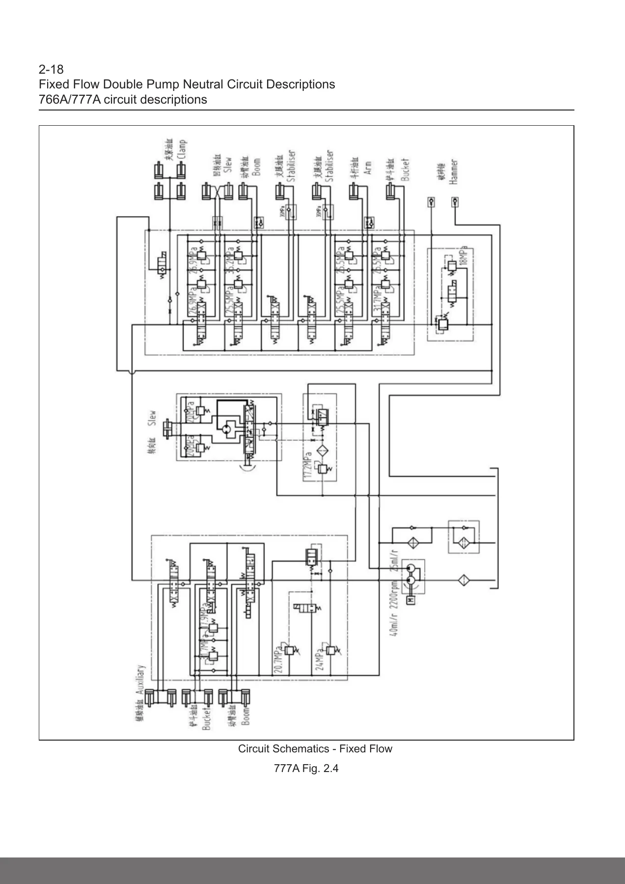
Hydraulics receive substantial coverage. The fixed-flow double pump data identifies pump sections and flow information, while valve sections provide specified pressure ranges and component descriptions. Circuit explanations trace oil flow through the hydraulic tank, pump sections, steering priority valve, loader valve, excavator valve, return filter and oil cooler. Separate fixed-flow circuit schematics are provided for CLG766A and CLG777A.
The fault-finding material addresses lack of hydraulic power, slow rams, a single service that fails or operates slowly, sticking spools, leaking oil seals, ram creep and overheated hydraulic oil. The testing section explains the use of pressure and flow equipment and provides procedures for pump-flow checks and loader-valve pressure testing. Once a faulty unit has been isolated, the removal and installation chapters continue with the actual valves, pump and cylinders.
IMAGES PREVIEW
Maintenance and Major Component Work
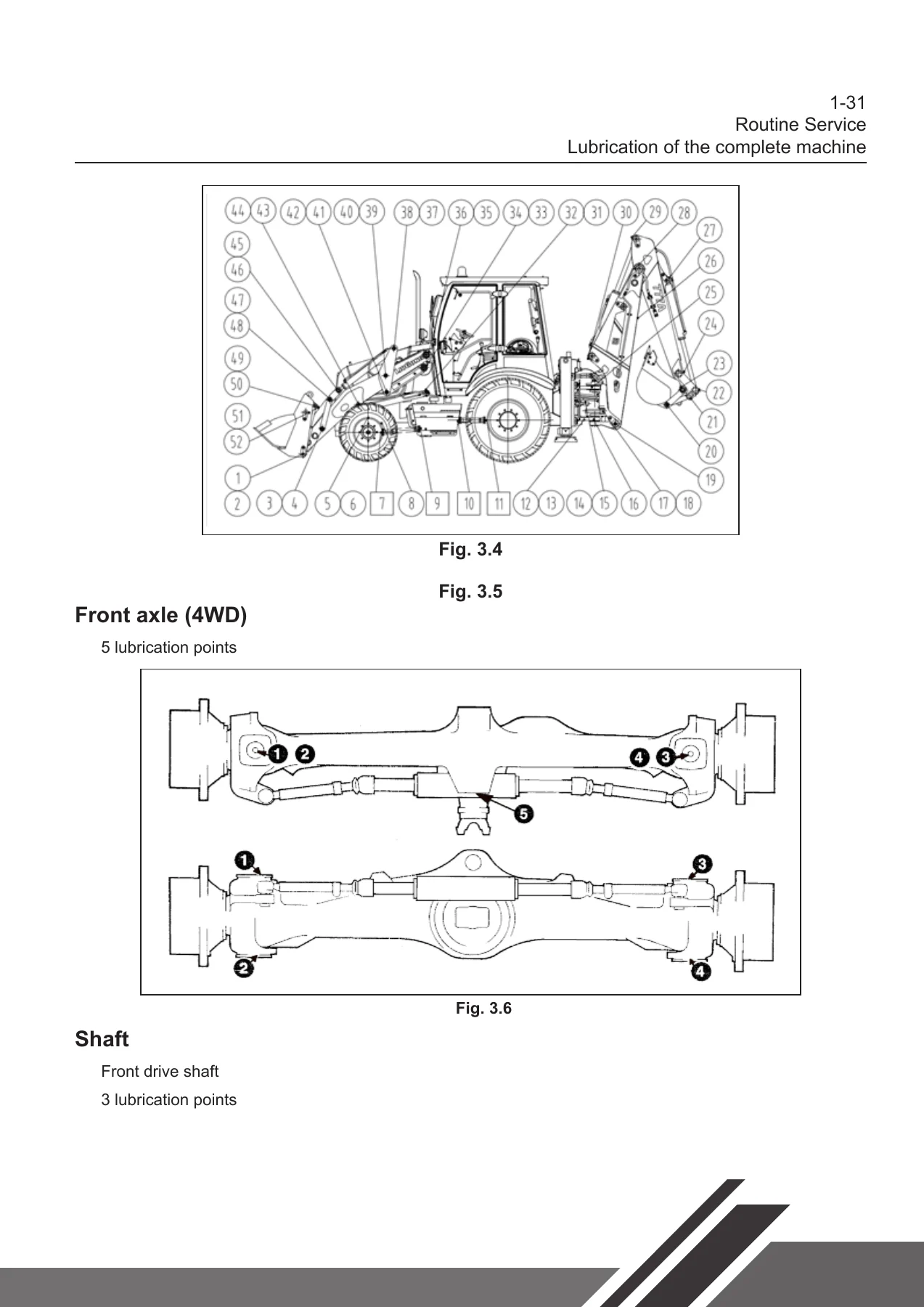
Routine-service pages cover engine oil and filters, cooling, fuel, gearbox oil, hydraulic oil and filters, axle and hub oil, brakes, air cleaner servicing, lubrication points and timed service intervals. Illustrated workshop sequences then cover loader arms, buckets and cylinders, backhoe bucket and boom components, swing seat, outriggers, side-shift hardware on the 777A, cab removal and installation, battery, instruments, radiator and steering components. Model-specific differences are retained in the manual instead of treating every backhoe configuration as identical.
Brake coverage includes both hydraulic and vacuum service-brake systems plus moist-brake and caliper-disc parking-brake sections. Steering coverage includes system operation, schematics, fault finding, pressure testing and hydraulic steering-unit work. The A/C chapter adds HFC-134a diagnosis, pressure checks, service procedures and component removal/installation, while the power-train chapter addresses axles, gearbox and torque converter assembly, and tyres and rims.
For Repair, Diagnosis and Correct Reassembly
The LiuGong CLG766A CLG777A Backhoe Loader Service Repair Manual PDF is a practical workshop reference for maintenance, troubleshooting, hydraulic diagnosis, electrical fault tracing, component removal and installation, and reassembly of the systems covered in the manual. Using the specified procedures, pressure data, torque values, service intervals, diagrams and illustrated component locations helps reduce guesswork when servicing the CLG766A or CLG777A and helps keep repairs aligned with the information provided for these machines.
After purchase, the manual is delivered as an instant PDF download. There is no physical book and no shipping wait. You can open the PDF on a phone, tablet or computer and print the pages you need for workshop use.
Reviews
There are no reviews yet.