
M44A2 Series 2-1/2-Ton 6×6 Multifuel Truck Unit Maintenance Manual TM 9-2320-361-20 1991
Original price was: $42.95.$24.95Current price is: $24.95.
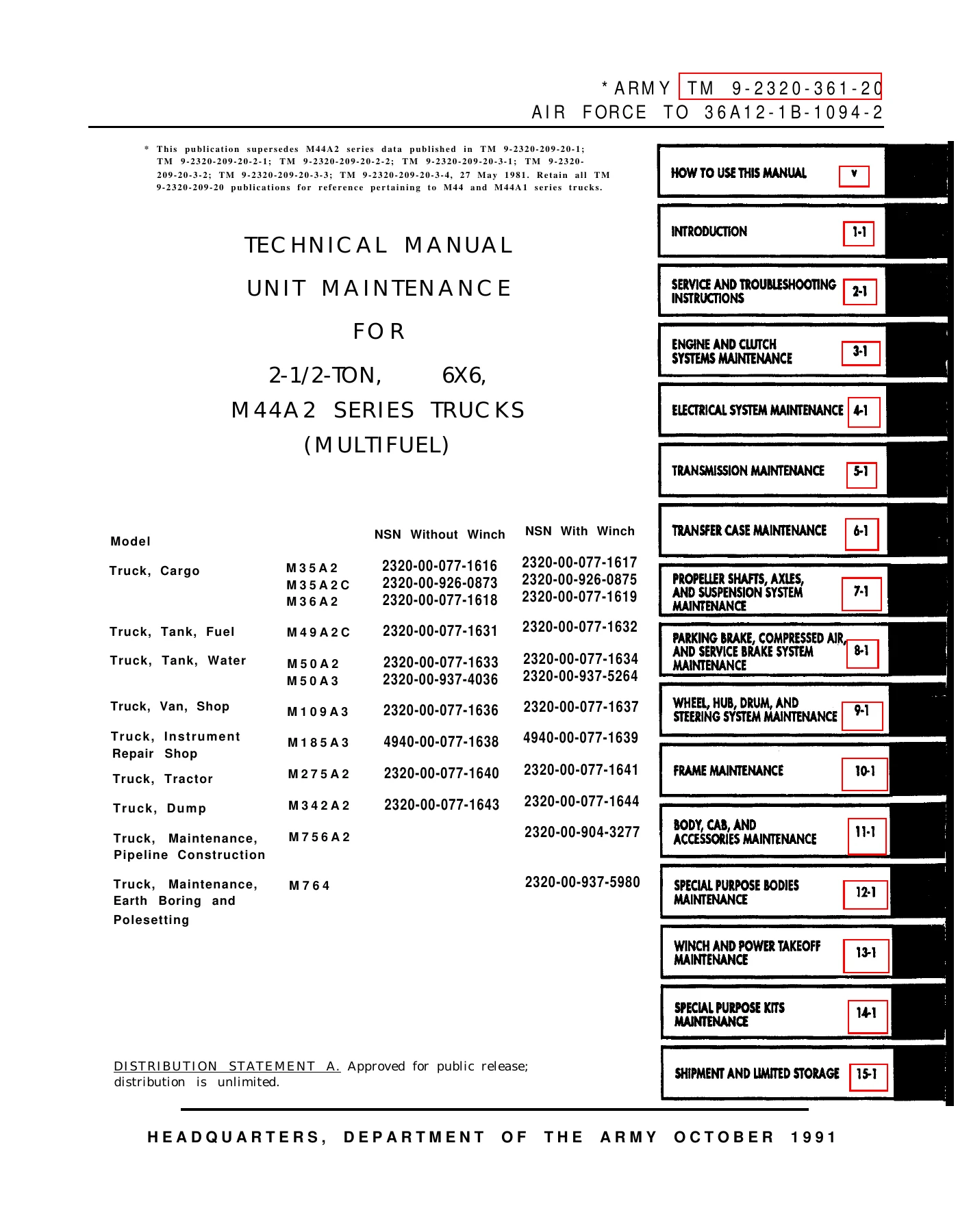
Unit maintenance technical manual TM 9-2320-361-20 / TO 36A12-1B-1094-2 for 2-1/2-ton 6×6 M44A2 series multifuel trucks, dated October 1991, covering service, troubleshooting, and repair of cargo, tanker, van, tractor, dump, pipeline, and earth-boring models.
Description
M44A2 Series 2-1/2-Ton 6×6 Multifuel Truck Unit Maintenance Manual TM 9-2320-361-20 1991
This Army technical manual is the unit-level service book for the 2-1/2-ton, 6×6 M44A2 family of multifuel trucks. Issued by Headquarters, Department of the Army on 25 October 1991 as TM 9-2320-361-20 and Air Force TO 36A12-1B-1094-2, it tells a unit mechanic how to inspect, troubleshoot, and replace the systems that keep these tactical trucks moving. The M44A2 Series 2-1/2-Ton 6×6 Multifuel Truck Unit Maintenance Manual TM 9-2320-361-20 1991 supersedes the M44A2 data that previously appeared in the TM 9-2320-209-20 series while directing readers to keep those older books for M44 and M44A1 trucks.
File Details
- Manual type: Unit maintenance technical manual
- Document numbers: Army TM 9-2320-361-20; Air Force TO 36A12-1B-1094-2
- Brand / series: U.S. Army M44A2 series 2-1/2-ton 6×6 multifuel trucks
- Language: English
- Page count: 1209
- File format: PDF
- Publication date: 25 October 1991
- Distribution: Statement A — approved for public release; distribution unlimited
Vehicles and Configurations Covered
The M44A2 Series 2-1/2-Ton 6×6 Multifuel Truck Unit Maintenance Manual TM 9-2320-361-20 1991 applies to the complete family listed on the title page, with and without front winch where NSNs are assigned:
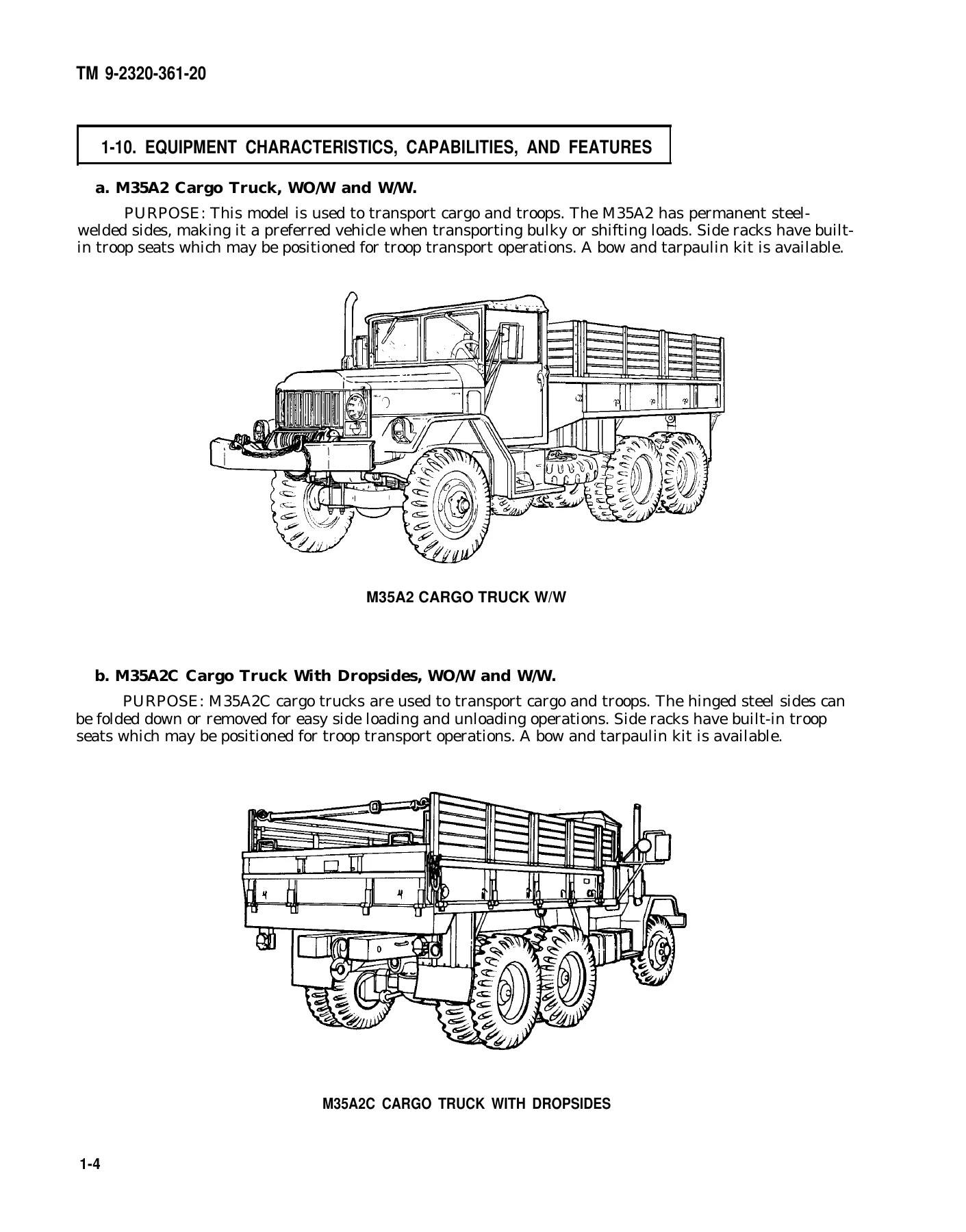
- M35A2 cargo truck — NSN 2320-00-077-1616 (without winch), 2320-00-077-1617 (with winch)
- M35A2C cargo truck with dropsides — 2320-00-926-0873 / 2320-00-926-0875
- M36A2 extra-long-wheelbase cargo truck — 2320-00-077-1618 / 2320-00-077-1619
- M49A2C fuel tank truck — 2320-00-077-1631 / 2320-00-077-1632
- M50A2 water tank truck — 2320-00-077-1633 / 2320-00-077-1634
- M50A3 water tank truck — 2320-00-937-4036 / 2320-00-937-5264
- M109A3 shop van — 2320-00-077-1636 / 2320-00-077-1637
- M185A3 instrument repair shop — 4940-00-077-1638 / 4940-00-077-1639
- M275A2 tractor — 2320-00-077-1640 / 2320-00-077-1641
- M342A2 dump truck — 2320-00-077-1643 / 2320-00-077-1644
- M756A2 pipeline construction maintenance truck (with winch) — 2320-00-904-3277
- M764 earth boring and polesetting truck (with winch) — 2320-00-937-5980
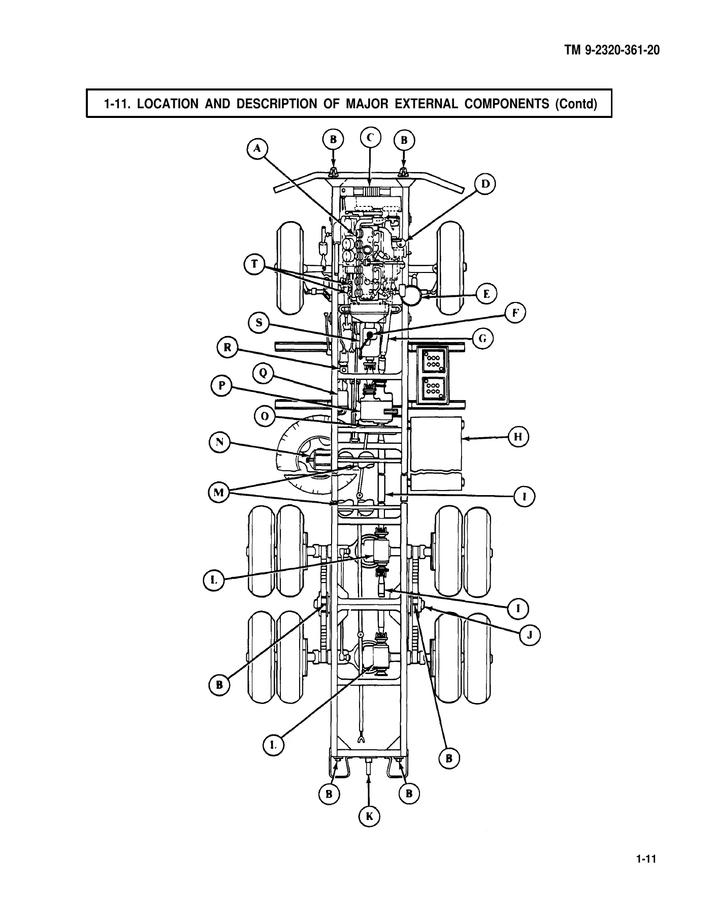
Shared chassis pieces — cab, Hercules multifuel engine, five-speed transmission, two-speed transfer case, 6×6 axles, air-over-hydraulic brakes, and 24-volt electrical system — are treated as common. Body-specific work (dropsides, dump hoist, fuel and water tanks, van interiors, fifth wheel, A-frame, auger and derrick) is isolated in the later chapters so you only open the procedures that match the truck on the stand.
Engine, Driveline, and Service Data in the Book
Table 1-2 records the unit-level equipment data a mechanic actually uses. Power comes from Hercules Engines, Inc. liquid-cooled multifuel six-cylinder in-line engines: naturally aspirated LD-465-1 and LD-465-1C, and turbocharged LDT-465-1C and LDT-465-1D. Engine weight is listed at 1,650 lb (749 kg). Idle is 650–700 rpm on early LD-465 pumps and 800–850 rpm on late LDT-465 pumps, with the exact figure stamped on the fuel-pump identification plate. Full-load governed speed is 1200–2650 rpm; no-load governed speed is 1200–2900 rpm. Gross brake horsepower is 130 hp minimum at 2600 rpm with the fan belt removed; net is 118 hp at 2600 rpm with the fan belt installed. Gross torque is 305 lb-ft at 1500 rpm; net is 297 lb-ft at 1500 rpm. Compression ratio is 22:1 and firing order is 1-5-3-6-2-4.
Capacities printed for unit service include cooling system 32 qt (30.3 L), crankcase only 20 qt (18.9 L), crankcase and filter 22 qt (20.8 L), each differential 6 qt (5.7 L), and a 50 gal (189.3 L) fuel tank on all vehicles. Transmission fill is 4.25 qt without PTO and 5.25 qt with PTO; transfer case is 7 qt with or without PTO. Oil pressure at idle with OE/HDO at 200°F is 10 psi minimum; at full load and 2600 rpm the band is 40 psi minimum to 75 psi maximum. The cooling thermostat starts to open at 180°F and is fully open at 200°F. Radiator cap pressure is 6.5 to 8 psi.
The electrical system uses two 12-volt 6TN batteries rated 100 A/h, a Prestolite AMA 5102UT alternator at 28 V / 60 A maximum with an internal regulator, and a 24-volt starter to specification MS53011-2. Transmission is Spicer / Dana 3053A synchromesh, five forward and one reverse, with first and reverse unsynchronized. Transfer case is Rockwell T-136-27 two-speed synchromesh with air-actuated front-axle engagement. Front winch capacity is 10,000 lb; M756A2 rear winch is 20,000 lb; M764 rear winch model W-3780-D is 14,000 lb. Tires are 9:00 x 20, 8 ply.
Chapters Covered
- How to Use This Manual
- Chapter 1 Introduction — General Information; Equipment Description and Data; Principles of Operation
- Chapter 2 Service and Troubleshooting Instructions — Repair Parts, Special Tools, TMDE, and Support Equipment; Service Upon Receipt; Preventive Maintenance Checks and Services (PMCS); Mechanical Systems Troubleshooting; Compressed Air and Brake System Troubleshooting; Electrical Systems Troubleshooting; STE/ICE Troubleshooting
- Chapter 3 Engine and Clutch Systems Maintenance — Engine; Engine Lubrication; Clutch; Air Intake; Turbocharger; Fuel System; Accelerator System; Exhaust System; Cooling System
- Chapter 4 Electrical System Maintenance — Charging; Starting; Instruments, Sending Units, Switches, and Horn; Lighting; Battery and Battery Box; Wiring Harness
- Chapter 5 Transmission Maintenance
- Chapter 6 Transfer Case Maintenance
- Chapter 7 Propeller Shafts, Axles, and Suspension System Maintenance — Propeller Shafts; Front and Rear Axle; Front and Rear Suspension
- Chapter 8 Parking Brake, Compressed Air, and Service Brake System Maintenance — Parking Brake; Service Brake and Hydraulic Systems; Compressed Air System
- Chapter 9 Wheel, Hub, Drum, and Steering System Maintenance — Wheel, Hub, and Drum; Steering System
- Chapter 10 Frame Maintenance
- Chapter 11 Body, Cab, and Accessories Maintenance — Body and Cab; Accessories
- Chapter 12 Special Purpose Bodies Maintenance — Cargo Body; Dump Body; Tank Body; Van Body; Earth Boring and Polesetting Truck Body; Pipeline Construction Body; Tractor
- Chapter 13 Winch and Power Takeoff Maintenance — Winch; Power Takeoff Controls and Linkage
- Chapter 14 Special Purpose Kits Maintenance — Winterization Kits; Van Body Primary and Secondary Heater Kit; Deepwater Fording Kit; A-Frame Kit; Mounting Kit; 100-Amp Alternator Kit; Troop Seat Mounting Kit and Seatbelt Kits
- Chapter 15 Shipment and Limited Storage — General Preparation of Truck for Shipment; Loading and Movement; Limited Storage
- Appendix A References
- Appendix B Maintenance Allocation Chart (MAC)
- Appendix C Expendable/Durable Supplies and Materials List
- Appendix D Torque Limits
- Appendix E Schematic and Wiring Diagrams
- Index
Taken together, the TM 9-2320-361-20 unit book gives a shop the symptom-to-task path for an M44A2 truck: find the complaint in the system troubleshooting indexes, confirm the fault with the printed tests or STE/ICE go/no-go chains, then execute the matching replacement or adjustment task with the INITIAL SETUP block (applicable models, parts, equipment condition, and warnings) sitting next to the keyed illustration.
Troubleshooting and PMCS Workflow
Chapter 2 is built for a mechanic who already has the truck in the bay. Unit PMCS appears as table 2-1. Mechanical troubleshooting is organized by system — engine, exhaust, manifold heater, cooling, fuel, transmission, clutch, and the remaining chassis groups — with malfunctions such as engine will not crank, engine cranks but will not start, starter cranks slowly, engine stops in service, misfire, surge, oil pressure faults, and blue exhaust. Compressed-air and brake tests cover air-hydraulic cylinder delivery, trailer-brake supply on the M275A2, compressor and governor behavior, low-pressure warning, wipers, and front-wheel-drive engagement air. Electrical troubleshooting walks charging (60-amp system), starting, gages, lighting, and heating, including the manifold heater ignition circuit. When STE/ICE is on hand, section VII supplies CI-engine go-chain and no-go-chain tests: VTM checkout, pulse tachometer installation, start and lubrication check, charging and battery voltage, warmup/coolant/oil pressure, governor/power, idle speed, compression unbalance, and fault isolation for no-crank, crank-no-start, low oil pressure, and charging or starter circuit problems. Printed check values include oil pressure 50–60 psi at 2600–2850 rpm, maximum governor speed 2850 rpm, and regulated charging near 28.0 ± 0.2 Vdc at the speeds called out in the tests.
Unit Repair Tasks You Can Perform From This Manual
Maintenance chapters are written as removal and installation tasks, not depot overhaul. Engine work at this echelon includes front and rear mount pads, oil dipstick tube, crankcase breather, oil filter and filter body, air cleaner and indicator, turbocharger oil feed and drain lines, in-tank and filter-head fuel components, injector-tube bleeding, manifold heater ignition unit and nozzle, accelerator pedal and stop/throttle cables, exhaust pipe and stack replacement (separate procedure for M50A2/M50A3), radiator service, belts, and related cooling parts. Electrical tasks cover the 60-amp alternator and conversion notes, starter and magnetic relay, instrument cluster gages, sending units, lighting, batteries, and harness work. Later chapters take the transmission, transfer case, propeller shafts, axles, springs, parking brake, hydraulic service brakes (including the longer front flexible lines called out in the warning summary), compressed-air compressor and governor, wheels and lockrings, steering, frame mounts, cab and body hardware, dump hoist, tanker plumbing, van equipment, earth-boring outriggers and derrick, pipeline A-frame, tractor fifth wheel, front and rear winches, PTOs, and the winterization, fording, heater, A-frame, 100-amp alternator, and troop-seat kits. Appendix B (MAC) states which of those actions stay at unit level and which go to higher maintenance; engine assembly overhaul is not a unit task in this book.
Safety Content Printed With the Procedures
The opening warning summary is part of the working text, not decoration. Exhaust-gas poisoning symptoms and first actions are listed first. Other cautions that appear again inside the tasks include flammable drycleaning solvent and diesel fuel, asbestos dust on brake shoes (wet brush only), compressed air limited to 30 psi with eyeshields, fuel-system work with the ignition off and eye protection on, radiator-cap and hot-oil burns, battery short and electrolyte hazards, tire lockring and inflation-cage rules, spring-leaf tension, air-reservoir drain before uncoupling lines, winch cable and shear-pin practice, and NBC handling of filter media. Cab data plates reproduced in chapter 1 include authorized fuels (VV-F-800 diesel, MIL-F-46005 CITE, MIL-G-3056 gasoline — not aviation gasoline), maximum road speeds by gear and transfer range, winch line-load limits, fording valve IN/OUT, and manifold-heater use below +20°F.
Related Publications Called Out in the Manual
Unit work frequently points to TM 9-2320-361-10 for operator actions, TM 9-2320-361-20P for repair parts and special tools, and LO 9-2320-209-12-1 for lubrication. Forms follow DA Pam 738-750 (TAMMS). Warranty coverage for listed major assemblies on selected models is referenced to TB 9-2320-209-14. Those companion numbers are cited so you know where this unit TM stops and the next book starts.
Use This Manual in the Shop
The M44A2 Series 2-1/2-Ton 6×6 Multifuel Truck Unit Maintenance Manual TM 9-2320-361-20 1991 supports unit diagnosis and replacement on every model in the series: no-start and misfire work on the LD-465 / LDT-465 multifuel engine, fuel-filter and injector-line service, charging and starting repairs on the 24-volt system, clutch and transmission/PTO linkage, transfer-case and front-drive air cylinder checks, brake and air-system leaks, spring and axle service, body and kit installation, and winch or tanker pump PTO jobs. Printed pressures, idle speeds, torque notes in appendix D, and the MAC keep the work inside unit authority instead of guessing from a generic truck book.
Using the correct TM 9-2320-361-20 procedure matters on these trucks because first and reverse are unsynchronized, front brake hoses of the wrong length can fail at full lock, lockrings can leave the rim if the tire is still inflated, and fuel and exhaust work is done around a hot multifuel engine. The steps, warnings, and table 1-2 values in this file are the ones written for unit mechanics on the M44A2 series.
Delivery is an instant PDF download after purchase. There is no printed shipment to wait for. Open the file on a shop computer, tablet, or phone and print the task pages you need for the truck on the floor.
Reviews
There are no reviews yet.