
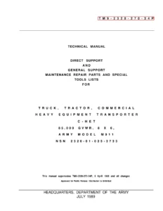
M911 C-HET Heavy Equipment Transporter Repair Parts & Special Tools Manual TM 9-2320-270-34P 1989
Original price was: $34.95.$20.95Current price is: $20.95.
Complete 975-page repair parts and special tools reference for the Army Model M911 Commercial Heavy Equipment Transporter C-HET, 85,000 GVWR, 8×6. TM 9-2320-270-34P covers direct support and general support parts identification across the engine, fuel system, transmission, axles, brakes, steering, cab, winch and other vehicle systems, with illustrated parts figures, SMR codes, NSN and part-number cross-references, repair kits and special tools.
Description
M911 C-HET Heavy Equipment Transporter Repair Parts & Special Tools Manual TM 9-2320-270-34P 1989
The M911 C-HET Heavy Equipment Transporter Repair Parts & Special Tools Manual TM 9-2320-270-34P 1989 is the detailed parts and support-equipment reference for the Army Model M911 Truck, Tractor, Commercial Heavy Equipment Transporter. The publication applies to the 85,000 GVWR, 8×6 C-HET identified by NSN 2320-01-025-3733 and is organized for Direct Support and General Support maintenance. Across 975 PDF pages it combines illustrated assembly breakdowns with repair-parts listings, special tools and extensive indexes designed to help identify the correct component and its associated stock or part information.
File Details
- Manual type: Direct Support and General Support Maintenance Repair Parts and Special Tools Lists
- Model: Army Model M911 C-HET
- Equipment: Truck, Tractor, Commercial Heavy Equipment Transporter, 85,000 GVWR, 8×6
- Technical manual: TM 9-2320-270-34P
- NSN: 2320-01-025-3733
- Date: July 1989
- Current as of: 14 April 1989
- Change included: Change No. 1 dated 20 April 1993
- Language: English
- Pages: 975
- Format: PDF
Illustrated M911 Parts Identification
This M911 C-HET parts manual is built around functional groups, figures and item numbers rather than a simple alphabetical parts list. Major assemblies are shown in detailed line drawings and exploded views, followed by the corresponding parts entries. Individual entries identify the item number, SMR code, FSCM, part number, description and usable-on information where applicable, together with the quantity shown for the figure. This format allows a technician to move from a physical assembly to its illustrated component and then into the detailed parts data.
The introductory section also explains the Source, Maintenance and Recoverability codes used throughout the publication. These codes communicate supply or requisitioning information, the maintenance category authorized to remove, replace, use or repair an item, and the required disposition of an unserviceable component. For work involving older M911 vehicles, this coding information is particularly useful when interpreting the many parts entries and understanding how each listed component was supported.
Engine and Powertrain Coverage
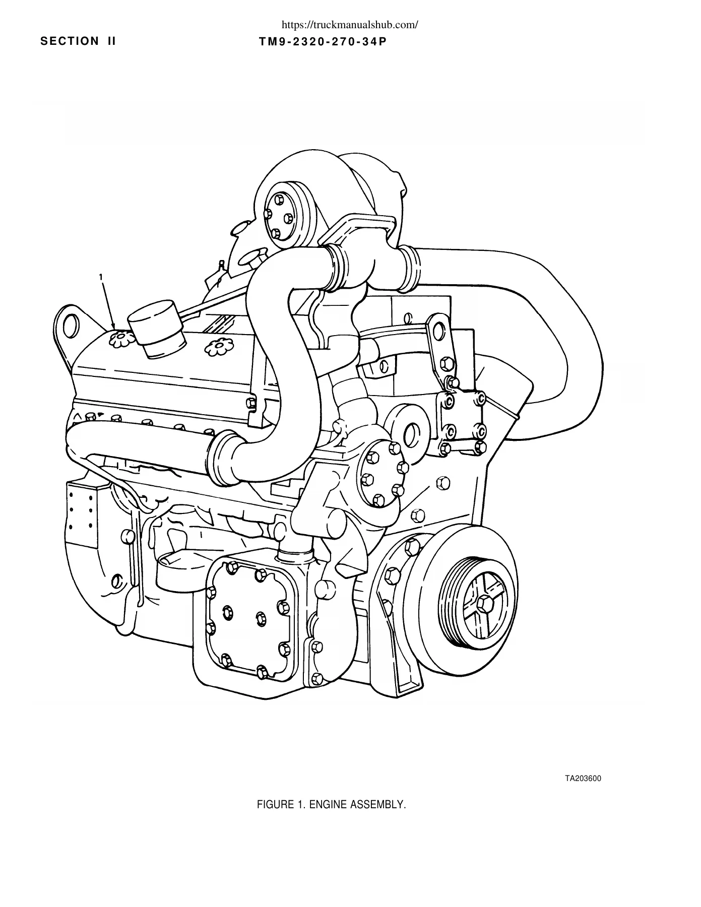
Engine coverage is extensive and includes illustrations and parts listings for the complete diesel engine assembly, cylinder block and liners, cylinder heads, crankshaft, bearings, timing components, flywheel, pistons and connecting rods, camshafts, valves, rocker gear and the lubrication system. The parts listings distinguish applications for 8V92T and 8V92TA engines where the components differ. The manual also identifies early and late 8V92T applications in several assemblies and shows 8V92TA-specific items such as aftercooler components.
The fuel and air sections continue into fuel injectors and injector exploded views, fuel-control tubes, fuel pump components, filters, air-cleaner assemblies, turbocharger parts, blower components, governor assemblies and starting-aid equipment. Illustrated breakdowns make it possible to trace individual components within assemblies such as the turbocharger, blower, governor and fuel injector instead of relying only on a component name.
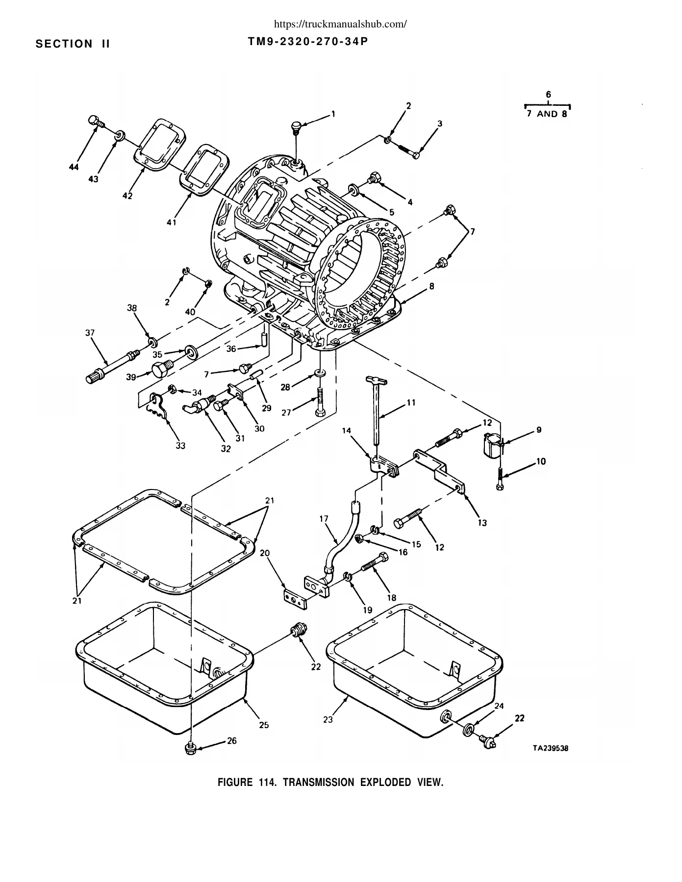
Beyond the engine, the M911 C-HET Heavy Equipment Transporter Repair Parts & Special Tools Manual TM 9-2320-270-34P 1989 contains major transmission and driveline coverage. It includes the auxiliary and hydraulic transmission, torque converter, clutch groups, valve and servo components, transmission oil system, transfer case, propeller shafts, front axle and rear tandem axle assemblies. Exploded illustrations extend into differentials, hubs, drums and other assemblies where individual internal parts must be identified.
IMAGES PREVIEW
Chapters Covered
- Introduction – scope, organization of the RPSTL, explanation of columns, SMR codes, indexes, special information and procedures for locating repair parts
- Group 01 – Engine – engine assembly; crankcase, block and cylinder head; crankshaft; flywheel assembly; pistons and connecting rods; valves, camshafts and timing systems; engine lubrication; manifolds; accessory drives
- Group 03 – Fuel System – fuel injectors; fuel pumps; air cleaner; supercharger, blower and turbocharger; tanks, lines and fittings; governor and controls; fuel filters; engine starting aids; accelerator and throttle controls
- Group 04 – Exhaust System – muffler, exhaust pipes and associated hardware
- Group 05 – Cooling System – radiator and heat exchanger; cowling and shrouds; thermostats and housings; water pump; fan assembly
- Group 06 – Electrical System – alternator; starting motor; engine safety controls; instrument control panel; sending switches; lights; warning switches; horn; batteries; chassis, engine, cab and instrument-panel wiring
- Group 07 – Transmission – transmission assemblies and shafts; shift controls; torque converter; hydraulic transmission; clutches; retarder components; servo and valve assemblies; oil pump, filters and cooler connections
- Group 08 – Transfer and Final Drive Assemblies – transfer case, output shaft, shifter components, air-shift system and lockup controls
- Group 09 – Propeller Shafts – propeller shafts and related parts
- Group 10 – Front Axle – front axle assembly, differential and steering-related axle components
- Group 11 – Rear Axle – pusher axle, tandem axle, axle shafts, housings, differentials, yokes, tandem-drive components and equalizing beams
- Group 12 – Brakes – service brakes; air-brake chambers and controls; tanks, lines, fittings and valves; air compressor; trailer brake connections and controls
- Group 13 – Wheels – hubs, brake drums, wheel assemblies, tires and tubes
- Group 14 – Steering – steering wheel mechanism; drag links; steering gear; power-steering pump, hoses, booster and reservoir
- Group 15 – Frame, Towing Attachments and Drawbars – frame and brackets; tow bars and pintle; spare-tire winch; fifth wheel and locking components
- Group 16 – Springs and Shock Absorbers – front and rear springs, pusher-axle air-lift components, shock absorbers and torque rods
- Group 18 – Body, Cab and Hood – radiator and headlight guard; hood and side covers; cab assembly and doors; windshield and glass; floor components; seats; stowage and winch platform
- Group 20 – Winch, Capstan, Windlass Power Control Unit and Power Takeoff – rear winch, winch assembly and exploded view, cable drum, hydraulic motor, controls, rotary pump, reservoir, PTO shaft and hydraulic connections
- Group 22 – Body Chassis and Accessory Items – air connectors, windshield washer and wiper, mirrors, air horn, heater and defroster, data plates and decals
- Group 47 – Gages – non-electrical weighing and measuring devices including air-pressure gage components
- Group 94 – Repair Kits – repair-kit listings
- Group 95 – General Use Standardized Parts – bulk materiel listings
- Section III – Special Tools – organizational, Direct Support and General Support special tools, special TMDE and support equipment
- Section IV – Cross-Reference Indexes – National Stock Number index, part-number index, and figure and item-number index
The breadth of these groups makes the manual much more than an engine-parts catalog. It follows the M911 through its complete mechanical and vehicle structure, from internal engine components to transmission, transfer case and axles, then through braking, steering, chassis, cab equipment and the heavy-duty winch and PTO system. Hundreds of illustrated figures give technicians a visual reference for identifying assemblies, subassemblies and individual pieces before consulting the accompanying itemized listing.
Find Parts by Figure, NSN or Part Number
The cross-reference system is one of the most useful features of this M911 repair parts manual. When a National Stock Number or part number is not known, the publication directs the user to identify the appropriate assembly or subassembly through the contents, locate the related illustration, identify the item number and then use the Figure and Item Number Index. When an NSN or part number is already known, the dedicated indexes cross-reference that number back to the relevant illustration and item.
The parts tables also identify Federal Supply Codes for Manufacturer and provide descriptions that can include component position, assembly relationship, kit association and engine applicability. Repair kits and bulk materials receive their own functional groups, while the Special Tools section lists tools and support equipment used at the applicable maintenance levels. This organization is especially useful when working from an illustrated assembly and needing to trace a small component, seal, bearing, fitting, fastener or repair kit to the exact listing.
Detailed References for Major M911 Systems
The manual contains particularly deep breakdowns of systems that contain many internal pieces. The engine section includes exploded views of items such as the crankshaft and bearings, pistons and connecting rods, fuel injector, turbocharger, blower and oil cooler. The transmission section breaks down internal housings, clutches, gears, valves and related components. Rear-axle and differential assemblies receive their own figures, as do air-brake components and the numerous lines, valves and fittings used throughout the braking system.
The winch section is similarly detailed, progressing from the complete rear winch and mounting arrangement to the winch assembly, an exploded winch view, cable drum, hydraulic motor, regulating and control valves, rotary hydraulic pump, reservoir and power-takeoff hardware. For an M911 being repaired, restored or maintained from incomplete assemblies, these figures can be valuable for understanding which pieces belong together and locating their corresponding parts entries.
Get the Correct M911 Parts Reference for Your Work
The M911 C-HET Heavy Equipment Transporter Repair Parts & Special Tools Manual TM 9-2320-270-34P 1989 gives you a single detailed reference for identifying repair parts, tracing assemblies, checking part and stock-number information, distinguishing applicable 8V92T and 8V92TA engine components, locating repair kits and reviewing the special tools assigned to Direct Support and General Support maintenance. Whether you are dealing with the engine, transmission, axle, air-brake system, steering, cab or winch, the illustrated figures and indexed parts data help reduce uncertainty before parts are sourced or an assembly is put back together.
Correct parts identification matters on a vehicle with this many system variations and individual components. Instead of relying on appearance alone, you can work from the manual’s figure numbers, item numbers, SMR information, NSNs and part-number cross-references. Purchase provides instant access to the PDF download after payment, with no physical book or shipping delay. Keep it available on a PDF-capable computer, tablet or phone for workshop reference, and print the pages or illustrated assemblies you need for a particular job.
Reviews
There are no reviews yet.