
M939 & M939A1 Series 5-Ton 6×6 Repair Parts and Special Tools List Volume 1 TM 9-2320-272-34P-1 – May 1988 PDF
Original price was: $39.95.$23.95Current price is: $23.95.
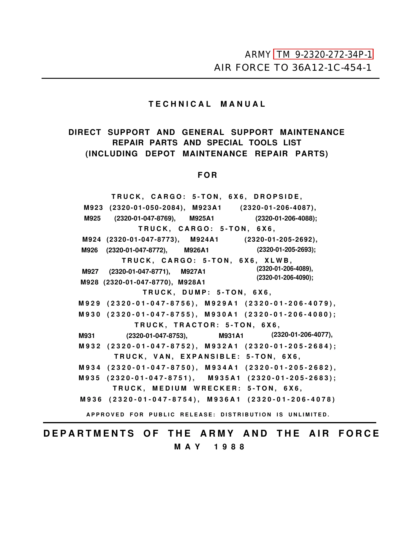
Volume 1 of the May 1988 M939 and M939A1 Series 5-ton 6×6 Direct Support and General Support Maintenance Repair Parts and Special Tools List, TM 9-2320-272-34P-1. Covers illustrated repair parts through Figure 308 for M923 through M945 series cargo, dump, tractor, expansible van, wrecker and chassis configurations, with NSN and part-number indexing.
Description
M939 & M939A1 Series 5-Ton 6×6 Repair Parts and Special Tools List Volume 1 TM 9-2320-272-34P-1 – May 1988 PDF
This M939 & M939A1 Series 5-Ton 6×6 Repair Parts and Special Tools List Volume 1 TM 9-2320-272-34P-1 – May 1988 PDF is the Direct Support and General Support Maintenance Repair Parts and Special Tools List for the M939 and M939A1 family of 5-ton, 6×6 vehicles. It identifies repair parts by illustrated figure and item number and supplies the associated SMR code, National Stock Number, part number, manufacturer code, description, usable-on information, unit of measure and quantity incorporated in the unit.
The manual covers a broad range of M939-series configurations, including cargo, dropside cargo, extra-long-wheelbase cargo, dump, tractor, expansible van, medium wrecker and chassis variants. Individual parts listings use usable-on codes to distinguish applications among specific models and winch or non-winch configurations, making this a detailed reference when identifying the correct component for a particular truck.
File Details
- Manual type: Direct Support and General Support Maintenance Repair Parts and Special Tools List, including depot maintenance repair parts
- Vehicle family: M939 and M939A1 Series 5-ton, 6×6 trucks
- Manual number: Army TM 9-2320-272-34P-1
- Air Force reference: TO 36A12-1C-454-1
- Date: 12 May 1988
- Information current as of: 1 June 1987
- Language: English
- Pages: 1118
- Format: PDF
Models Covered
The M939 Series repair parts manual identifies applications for M923, M923A1, M925, M925A1, M924, M924A1, M926, M926A1, M927, M927A1, M928, M928A1, M929, M929A1, M930, M930A1, M931, M931A1, M932, M932A1, M934, M934A1, M935, M935A1, M936, M936A1, M941, M941A1, M945 and M945A1. The model table distinguishes trucks with and without winches as well as the different cargo, dump, tractor, van, wrecker and chassis arrangements.
Usable-on codes are carried into the parts listings so that components restricted to particular models can be separated from parts applying across the series. This is especially useful where fuel-tank arrangements, wiring harnesses, frames, brake plumbing, body components and other assemblies differ by truck configuration.
Illustrated Parts Identification
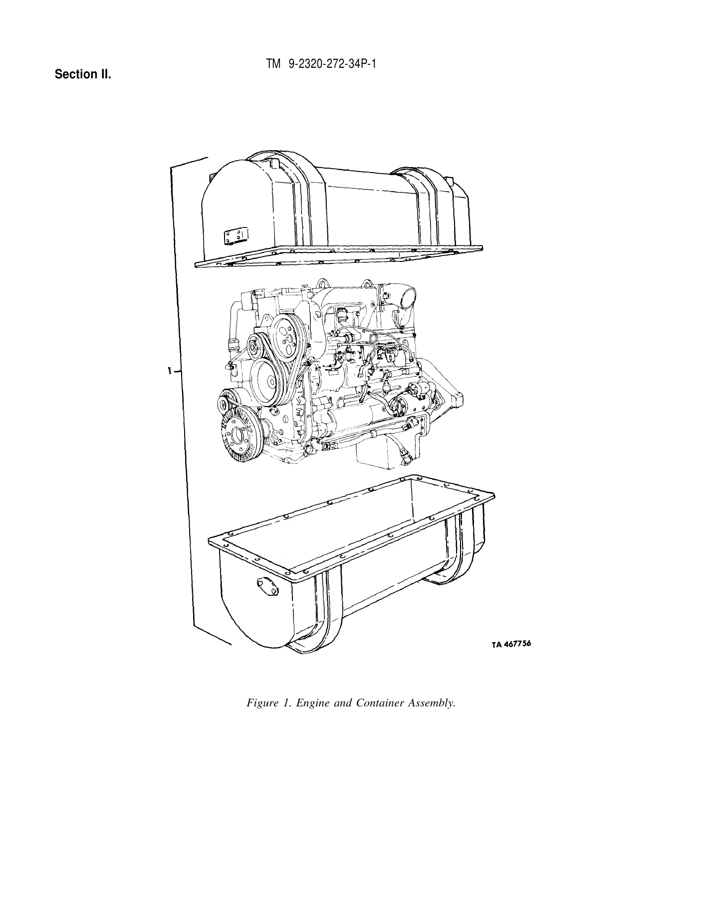
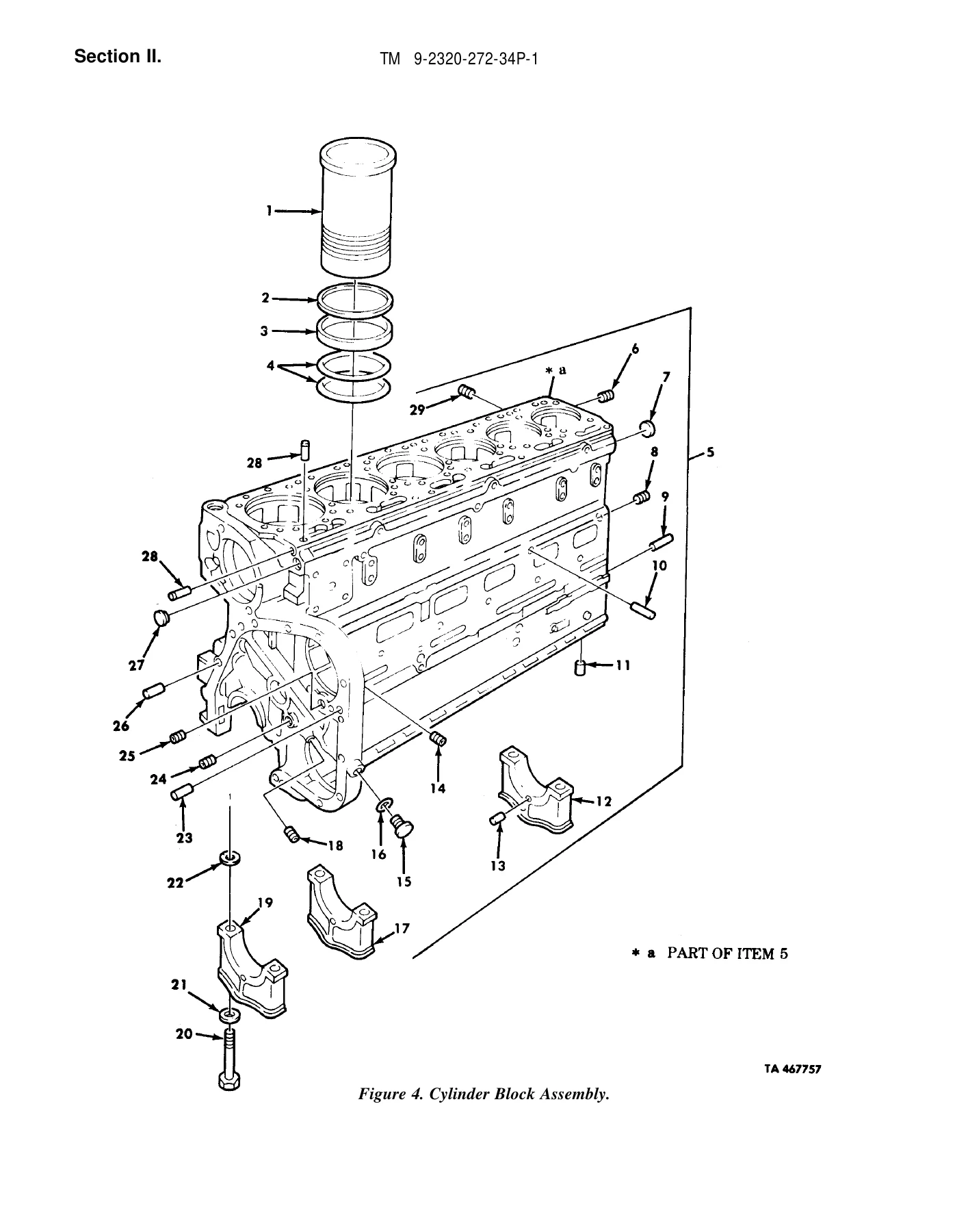
Section II is arranged by functional groups and uses detailed line illustrations to show assemblies and their component item numbers. The accompanying parts pages identify the component against its figure callout and provide supply and application information. Examples range from complete engine assemblies and internal engine components to fuel plumbing, electrical harnesses, transmission assemblies, axles, braking equipment, steering, chassis and body hardware.
The engine listings identify the NHC 250 engine with AFC fuel pump and include exploded illustrations for the cylinder block, cylinder heads, crankshaft, piston and rod assemblies, valve gear, lubrication equipment and related engine systems. Throughout the manual, individual entries may also identify configuration or serial applicability where the parts differ.
Parts Data and Supply Information
Beyond exploded drawings, TM 9-2320-272-34P-1 explains how to interpret the supply information attached to each listed item. The five-position SMR code identifies how an item is obtained, the maintenance level authorized to remove or replace it, the level capable of complete repair and the required disposition of an unserviceable item. Parts entries also use National Stock Numbers and manufacturer part numbers for identification and requisitioning.
The Description and Usable on Code column is particularly important across the M939 family because uncoded items apply to all models while coded entries identify the specific vehicle configurations on which a component is used. The manual also explains FSCM codes, units of measure, quantities incorporated in an assembly, kit parts and bulk materials.
Chapters Covered
- Section I – Introduction
- Scope and organization of the Repair Parts and Special Tools List
- Explanation of illustrations, SMR codes, NSNs, part numbers, FSCM, usable-on codes and quantities
- Special information, associated publications and methods for locating repair parts
- Section II – Repair Parts List
- Illustrated spares and repair parts arranged by functional group, figure and item number
- Group 01 – Engine
- Engine and container assembly, mounts and lifting bracket
- Cylinder block, cylinder heads, crankshaft, flywheel, pistons and connecting rods
- Camshaft, valve gear, rocker assemblies and timing components
- Lubricating oil filter, oil pump, oil pan and oil cooler
- Air intake and exhaust manifolds and accessory drive
- Group 03 – Fuel System
- Fuel injectors and AFC and VS fuel-pump assemblies
- Fuel-pump housings, governors, filters and water separator
- Air cleaner and air-intake components
- Single and dual fuel tanks, supply, return and vent lines
- Ether start, primer pump, accelerator controls and related linkage
- Group 04 – Exhaust System
- Muffler, exhaust pipes and related components
- Group 05 – Cooling System
- Radiator, hoses, mounts and surge tank
- Thermostat, water manifold, water pump and compressor coolant lines
- Fan clutch, fan and belts
- Group 06 – Electrical System
- Alternator, starter and shutdown valve
- Control panel, instrument cluster, switches, lamps and circuit protection
- Horn, batteries, battery box and slave receptacle
- Front and rear wiring harnesses for cargo, chassis, wrecker, dump, tractor and van configurations
- Group 07 – Transmission
- Transmission mounting and shift controls
- Torque converter and lockup clutch
- Transmission housing, planetary carrier, shafts and clutch assemblies
- Control valves, oil pump, cooler, filter and tubing
- Group 08 – Transfer Case Assembly
- Transfer housing, shafts, clutch and synchronizer
- Transfer controls, air-actuated controls, shift mechanism and oil pump
- Group 09 – Propeller Shafts and Universal Joints
- Drive shafts between transmission, transfer case, front axle and rear axles
- Group 10 – Front Axle
- Axle assembly, differential, carrier, gears, pinion, spindle, universal shaft and knuckle
- Group 11 – Rear Axle
- Forward-rear and rear-rear axle assemblies, differentials, carriers, gears and pinions
- Group 12 – Brakes
- Parking brake and axle brake assemblies
- Treadle valve, brake chambers, relay and check valves
- Air reservoirs, brake plumbing, governor and air compressor
- Trailer brake controls, protection valve and service/emergency lines
- Group 13 – Wheels
- Wheel and beadlock assemblies, front and rear hubs and drums, tire and tube assembly
- Group 14 – Steering
- Steering column, wheel, tie rods and steering gear
- Power-steering pump, hydraulic lines and steering cylinder
- Group 15 – Frame and Towing Attachments
- Frames for cargo, dump, wrecker, van, tractor, long-wheelbase cargo and chassis models
- Bumpers, shackles, pintle components and spare-wheel carriers
- Fifth-wheel assemblies and mounting components
- Group 16 – Springs and Shock Absorbers
- Front and rear leaf springs, shock absorbers and torque rods
- Group 18 – Body, Cab and Hood
- Front guard, hood, cab, doors, windshield, seats and related hardware
- Toolboxes and equipment mounting components
- Cargo body and long-wheelbase cargo body assemblies
- Dump body, hoist mounting, tailgate and tailgate controls through Figure 308
- Section IV – National Stock Number and Part Number Index
- National Stock Number index with figure and item cross-references
- Part-number index for locating listed items by manufacturer part number
This volume provides a detailed illustrated route from an assembly on the vehicle to the corresponding repair-part listing. A technician can locate the functional group, identify a component on its figure, use the item number to find the detailed listing and then cross-reference the part or National Stock Number in the index.
Volume 1 Coverage
This PDF is Volume 1. Its illustrated repair-parts section runs through Figure 308, Dump Tailgate Controls, Safety Catch, and Related Parts. The publication table of contents marks Figure 309, Wrecker Crane and Body Assembly, as the beginning of Volume 2 of 2. Buyers needing the later illustrated groups identified for Volume 2 should not treat this Volume 1 file as containing those later figure pages.
This is primarily an illustrated repair-parts and supply reference rather than a step-by-step repair procedure manual. Its strength is identifying assemblies, individual components, model applicability, NSNs, part numbers and maintenance/supply coding needed alongside direct and general support maintenance work.
Identify the Correct M939 Series Parts with Confidence
The M939 & M939A1 Series 5-Ton 6×6 Repair Parts and Special Tools List Volume 1 TM 9-2320-272-34P-1 – May 1988 PDF supports parts identification for engine, fuel, cooling, electrical, transmission, driveline, axle, brake, steering, suspension, frame and body work across the covered M939-series trucks. The exploded illustrations and application codes help distinguish components before ordering or assembling parts, while the NSN and part-number indexes provide a direct route back to the correct figure and item.
Correct parts identification matters when similar M939 and M939A1 configurations use different tanks, lines, harnesses, frames, body equipment or other components. Having the illustrated parts breakdown and the corresponding supply data together reduces guesswork when preparing maintenance and parts requirements. Purchase provides instant PDF delivery after payment – there is no physical book or shipping wait. The file can be opened on compatible phones, tablets and computers and pages can be printed whenever a paper reference is useful in the workshop.
Reviews
There are no reviews yet.