
MAN B&W 7L23/30 Instruction Book Part II Sections 311-320 – Diesel Engine Service Manual PDF
Original price was: $68.95.$42.95Current price is: $42.95.
Complete MAN B&W 7L23/30 Instruction Book Part II (Sections 311-320) for the Bazan 15 engine. Covers fuel injection, camshaft and drive, control and safety systems, starting system, lubricating oil, fuel oil, cooling water, driven machinery, tools, and specific plant information. 280-page PDF with Woodward governor and synchronizing motor documentation included.
Description
This is the MAN B&W 7L23/30 Instruction Book Part II, Sections 311–320 — the service and maintenance manual for the 7L23/30 marine diesel engine, also designated Bazan 15. Published by MAN B&W Diesel A/S, Holeby Diesel, this 280-page PDF covers fuel injection, camshaft and camshaft drive, control and safety systems, starting system, lubricating oil system, fuel oil system, cooling water system, driven machinery, tools, and specific plant information. The manual also incorporates the Woodward UG Dial Governor manual (03040D) and the Woodward Speed Adjusting (Synchronizing) Motor bulletin (03505C) within the relevant sections, giving you the complete control system documentation alongside the engine instruction book.
File Details
- Manual Type: Instruction Book / Service Manual
- Brand: MAN B&W Diesel A/S (Holeby Diesel)
- Engine Type: 7L23/30 (also referred to as 7L23-30)
- Plant Designation: Bazan 15
- Document: Instruction Book Part II, Sections 311–320
- Registration No.: 24231
- Language: English
- Page Count: 280 pages
- File Format: PDF
- Section Editions: 07H, 06H, 11H, 12H1 (1986.09.09), 02H, 22H, 01H, 13H (1987.03.02), 09H, 05, 06, 03H
Chapters Covered
- Section 311 — Fuel Injection
- Section 312 — Camshaft and Camshaft Drive
- Section 313 — Control and Safety Systems, Automatics and Instruments
- Section 314 — Starting System
- Section 315 — Lubricating Oil System
- Section 316 — Fuel Oil System
- Section 317 — Cooling Water System
- Section 318 — Driven Machinery
- Section 319 — Tools
- Section 320 — Specific Plant Information
Section 311 — Fuel Injection
The fuel injection section describes the fuel injector in detail: the nozzle holder with threaded pipe stub for the high-pressure pipe, the adjusting screw, spring, and spring spindle for setting nozzle needle initial tension. Three sealing O-rings are arranged so that leak oil from the nozzle needle is led out between the two lowest O-rings into the space between the high-pressure piping and protection tubing, while cooling medium inlet and outlet flow between the two uppermost O-rings when operating with a cooled nozzle. Diesel oil is normally used as the cooling medium, led through bored ducts in the holder to the conical bottom surface of the nozzle. The nozzle and needle are lapped together as a matched pair and cannot be replaced individually. The shielded high-pressure pipe connection between injection pump and fuel injector is covered, with connection tapers and tightening torques of 40 Nm at the connections and 60 Nm for the union nut with Loctite 242. Disassembly and assembly procedures for the fuel injector include cleaning with kerosene, nozzle hole cleaning with the supplied special drill, checking nozzle holes with the test mandrel (if the mandrel enters one hole, the nozzle must be scrapped), checking for oval wear with a magnifying glass, and cleaning the cooling chamber and ducts. Assembly requires molybdenum sulphide on all threads, renewed O-rings, and a nozzle nut tightening torque of 100 Nm. Testing uses test pipe 0573 for cooling oil system sealing and test pipe 0484 for opening pressure verification at 320 bar. The shattering test and atomization check are described, with a warning about fuel jets penetrating the skin. Tools 0148 (fuel valve dismantling) and 0237 (fuel valve seat grinding) are specified.
Section 312 — Camshaft and Camshaft Drive
The camshaft consists of a number of sections bolted together, each cylinder having its own section comprising fixed cams to operate the fuel pump, inlet valve, and exhaust valve. On one end of the camshaft a hub 1448 carries a gear wheel 1260 which, through an intermediate wheel, connects to a gear wheel on the crankshaft. The gear wheel on the camshaft is secured to the hub by screws 1082, and the screw holes are oblong so the camshaft can be turned relative to the gear wheel and crankshaft. Lubricating oil for the camshaft bearings is supplied through a bore in the bearing nearest the gear wheel and passes through a central bore to the individual shaft sections. The intermediate gearing consists of 2 gear wheels bolted together and fitted on a common bush 0349, running on a shaft pin 0250 attached to the engine frame. The gear wheel drive and camshaft do not require maintenance, but the manual notes that before taking out the camshaft the fuel oil primary pump must be dismantled, and that correct angles between the middle of the fuel pump cams must be checked during re-assembly. Camshaft adjustment can be checked with pin gauges 0197 and 0286 placed as illustrated on plate 31251.
Section 313 — Control and Safety Systems, Automatics and Instruments
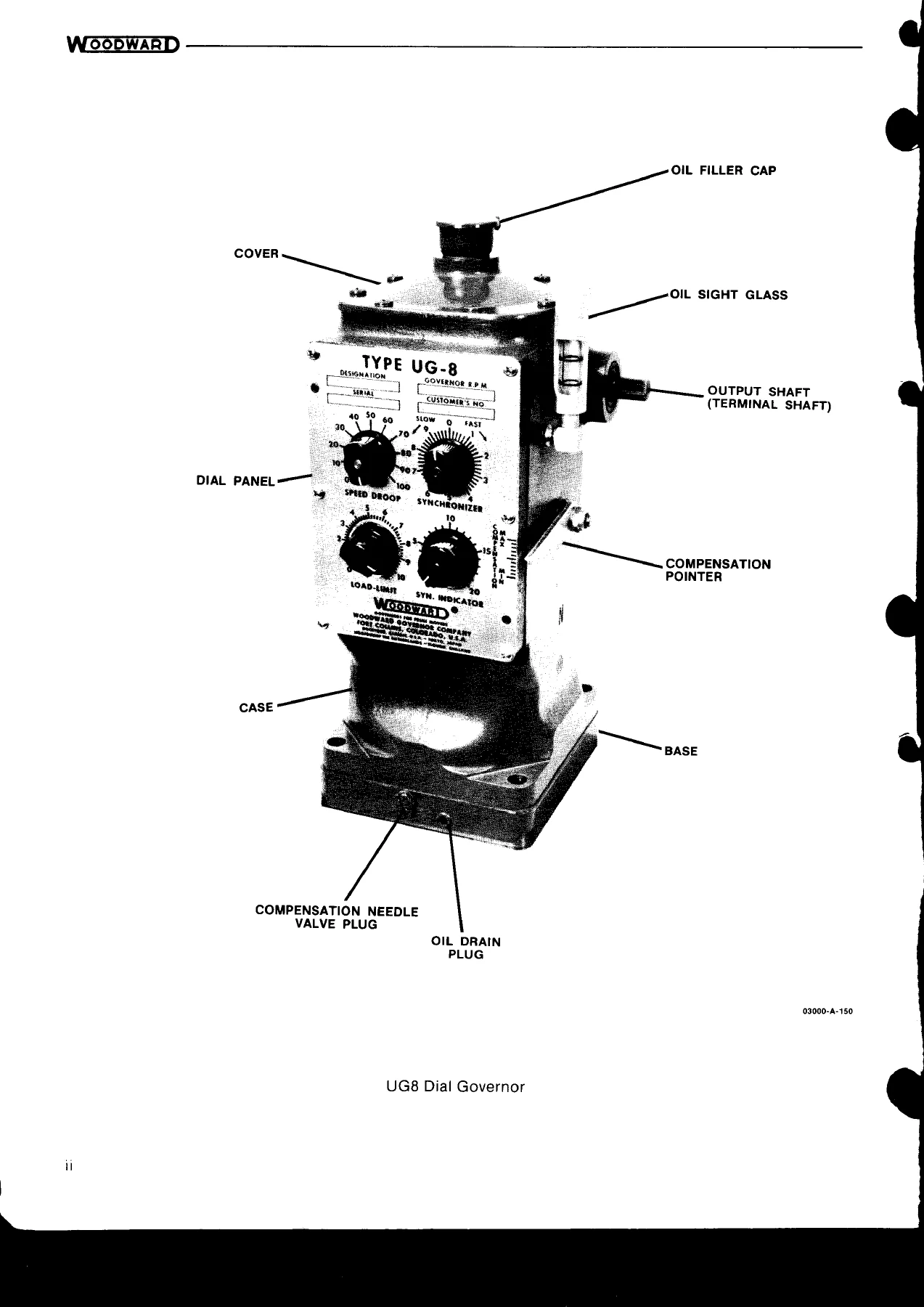
This substantial section covers the Woodward hydraulic governor, its drive at the flywheel end (cylindrical gear wheel 1586 driven by a gear wheel on the camshaft, plus bevel gears 1308 and 2476), and its linkage through levers and pull rods to a longitudinal regulating shaft with a two-piece arm for each fuel pump. The overspeed trip is described in detail: a spring-loaded flyweight 1106 swings outwards when the pre-set tripping speed is exceeded, pressing down arm 0583 (locked by pin 3897 and spring 3986) and spindle 4787, opening the Enots valve 5122. Compressed air (4.5–7.5 bar) then passes to stop cylinder 5211, which turns the fuel pump regulating shaft to STOP position. Manual stop button 2185 and reset knob 4143 (4232) are covered, along with functional test and adjustment procedures using the tubular pin spanner (tool 0146). The smoke limiter system is described: an index cam on the fuel injection pump regulating shaft, an analog pick-up giving a voltage signal proportional to pump index, and a charge air pressure transmitter giving a milliamp signal. When excess air drops below the pre-set limit, the control system activates a magnetic valve for air supply to jet assist nozzles in the turbocharger, accelerating the T/C and building up excess air. The instrument panel incorporates pressure gauges for LT water inlet to air cooler, HT fresh water inlet to engine, lubricating oil inlet to filter, charging air outlet from cooler, nozzle cooling oil inlet to fuel valves, compressed air inlet to engine, and engine/turbocharger RPM tachometers. Thermometers for local reading include LT water inlet and outlet, HT fresh water inlet and outlet each cylinder, lubricating oil inlet and outlet, charge air inlet and outlet, fuel oil inlet and filter, nozzle cooling oil outlet, and exhaust gas outlet each cylinder and turbocharger. Alarm and shut-down functions are listed: shut-down switches for too low lubricating oil pressure (inlet engine), too high HT fresh water temperature (outlet engine), and too high engine speed (lower speed); alarm switches for leaking fuel oil, too low lubricating oil pressure, too low prelubricating oil pressure, too high pressure drop across lubricating oil filter, too high HT fresh water temperature, too low starting air pressure, and too high engine speed (overspeed). Adjustment and test procedures for on/off pressostates (range spindle, differential spindle, locking screw) and thermostates (range spindle, differential spindle) are detailed, along with functional testing of the level switch LAL 25 for missing prelubricating oil, pressure transmitters, and PT 100 analog temperature transmitters. The section includes the Woodward UG Dial Governor manual 03040D with full installation, principles of operation, governor operation and adjustments, troubleshooting chart, replacement parts, and auxiliary equipment including synchronizer motor and solenoid shutdown, low lube oil pressure shutdown, magnetic speed pickup, and micro switches. The Woodward Speed Adjusting (Synchronizing) Motor bulletin 03505C covers the Bodine V10R motor with integral worm gear speed reducer, lubrication instructions, and adjustments.
Section 314 — Starting System
The starting air system comprises the starting piston valve 3048, the starting air distributor 0190, and the starting valves on the cylinder heads. When the shut-off valve of the starting air receiver is opened, air enters the starting piston valve through space B and continues through a small bore in valve piston 2336 to space D, keeping the valve closed against its seat by air pressure and spring 2247. Starting is effected by pressing starting button 2425, relieving pressure in chamber D through bore H. For electrically started (remote-controlled, automated) plants, venting of chamber D takes place through a solenoid valve. Air pressure at B pushes forward and opens valve piston 2336, allowing air to enter chamber L. The guide of the valve piston blocks vent duct K. When the engine fires and the starting button is released, pressure in chamber D presses the valve piston against its seat and the starting air pipes are vented through duct K. Chamber L opens into a main M supplying starting air to the cylinders and a bore N to the starting air distributor. Air enters the distributor through bore N and flows through the milled groove in distributor disc 1268 to uncovered bores, passing through pipes to the respective starting valves. During rotation of the distributor disc, the bores are uncovered corresponding to piston positions. Chamber AB in all starting valves is pressurised through pipes M from the starting piston valve, but valves are kept closed by springs 30602/0584 and slides 30602/0673. When air from the distributor enters chamber T, the slide is pressed inwards and valve spindle 30602/0128 admits starting air when cylinder pressure is lower than starting air pressure. The starting air distributor is mounted on the engine with distributor disc 1268 loosely attached to the shaft cone; screw 0734 is removed and check pin 3137 inserted in the aperture, then the distributor disc is turned until the check pin enters the guide notch, after which nut 1446 is tightened and locked. Maintenance recommends a thin layer of Molykote on contact faces between distributor disc and housing. The pressure reduction station for the high-pressure sealing oil pump is described: the pump is driven by air from the built-on internal compressed air system through a pressure reduction valve, manometer, and safety valve. Adjustment of air pressure is by the knob on top of the valve (clockwise raises pressure, anticlockwise lowers). Maintenance of the pressure reduction valve involves cleaning dirt from the disc area, and the safety valve opening pressure is set to 7 bar (adjustable with the lock screw after removing the plastic cap).
Section 315 — Lubricating Oil System
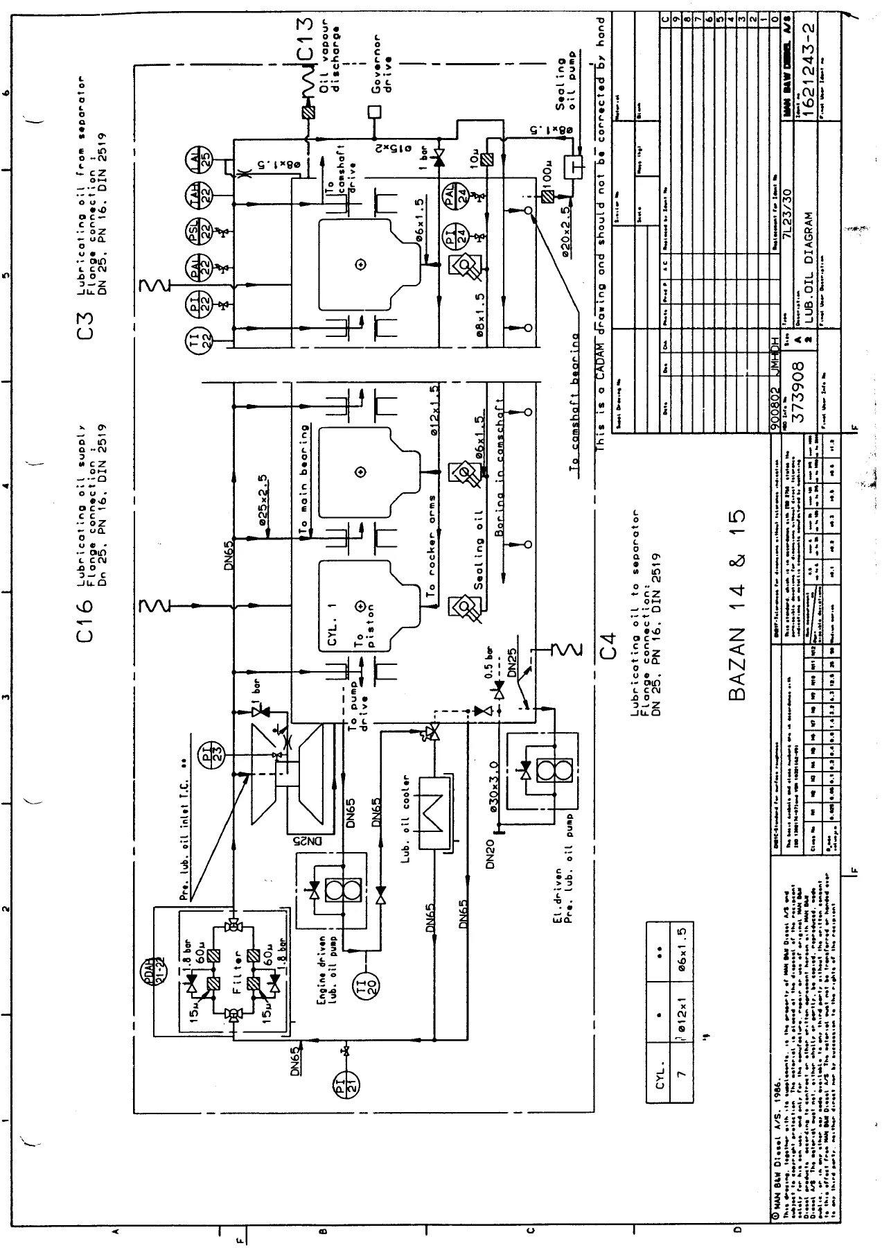
All moving parts of the engine are lubricated with oil circulating under pressure in a closed system. The lubricating oil pump presses oil through a cooler and filter to the main lubricating pipe, from where it is distributed to individual points. The engine plant is equipped with an electric-driven pump for priming the lubricating oil system before starting. The lubricating oil pump is of the gear wheel type, mounted on the end of the engine remote from the flywheel, driven through a claw coupling from the free end of the crankshaft or through a resilient gear transmission. The overspeed trip is fitted to the end cover of the pump. The pressure regulator forms part of the lubricating oil pump; adjustment is by removing cap nut 0149 and turning adjusting screw 0416. The lubricating oil filter is a double filter generally used with only one filter chamber in operation and the other in stand-by; if the operating chamber needs servicing, operation can be switched to the other chamber without interruption in oil supply. Each filter chamber has 1 or 2 replaceable paper cartridges of fineness 10–15 microns. A filter basket (central element) acts as a safety filter with fineness about 60 microns. If pressure drop across the filter exceeds 2.0 bar, a release valve opens and bypasses the 10–15 micron filter element, leaving only the 60 micron safety filter. Elements should be replaced at a pressure drop of 1.5 bar (22 psi). The thermostatic valve is designed as a T-piece whose inlet is through cover A (under which thermostatic element 0543 is located), outlet to engine marked B, and outlet to cooler marked C. During warming up, oil bypasses the cooler; when oil reaches normal temperature, a controlled amount passes through the cooler. The valve cannot be set or adjusted and requires no maintenance. The lubricating oil cooler is of the plate type, consisting of a number of heat transfer plates corresponding to actual engine performance, cooled by the low temperature cooling water system. Each plate has a gasket sealing against the adjacent plate, and the whole plate pack is mounted in a common frame. The prelubricating pump is a three-screw type; working parts are the three screws and surrounding casing within which they rotate. Thread surfaces form tight seals both relative to each other and to the pump casing. The pump is self-priming and built for one rotational and one pumping direction. A built-in adjustable bypass valve allows adjustment of pump delivery head during operation; at delivery ex work the pre-set pressure is about 3 bar. The shaft seal is a mechanical seal formed by two flat sealing surfaces in contact with each other. Before starting, after installation or reassembly, the pump must be filled with oil. Direction of rotation must be checked (three-phase motors: reverse two electric connection wires if wrong). Starting should always take place with fully open valves in suction and delivery lines. The bypass valve is set with a pressure gauge (turn screw on end cover beneath trade mark; right increases opening pressure). Periodic overhauls are not normally necessary, but after 3–6 years shaft seals usually need replacement due to aging rubber parts. Troubleshooting covers wrong direction of rotation, pump oil output too small, pressure too low, drive motor difficult to start, pump noisy (cavitation), and oil leakage at shaft seal. Mechanical seal type 2/W-seat (Crane) is described in detail with dismantling and reassembly procedures. Lubricating oil specification for B&W 4-stroke engines: system oil with detergency level at least corresponding to API service CC/CD for marine application; for stationary purposes, API service CD. TBN (total base number) indicates alkalinity and neutralising effect on acids from sulphur in fuel oil. TBN is reduced gradually during operation, influenced by sulphur content in fuel oil and amount of refilling. After a certain time, TBN stabilises at a lower value (TBN equilibrium). The relationship between fuel oil sulphur content and adequate TBN is illustrated. Recommended viscosity of lubricating oil is within SAE Class 30. A list of HD lubricating oils SAE 30 from BP, Castrol, Chevron, Elf, Esso/Exxon, Fina, Gulf, Mobil, Norol, Nynas, Shell, Texaco, and Total is provided with specific gravity, flash point, viscosity at 40°C and 100°C, TBN, API class, and FZG load. Maintenance of lubricating oil condition: contamination by small particles from combustion, water (fresh or salt), and the importance of analysing oil samples. The engine bearings are protected by the full-flow lubricating oil filter with 15 micron cartridges and 60 micron safety filter. Centrifuging is superior to other methods for cleaning lubricating oils; optimum cleaning effect is achieved by keeping oil at low viscosity for a long period in the centrifuge bowl. Low viscosity is obtained by preheating to 85–95°C. Slow passage through the centrifugal separator is obtained by reduced flow rate and operating 24 hours a day. For detergent type lubricating oil, flow rate is usually reduced to 15–25% of rated flow. For keeping the amount of lubricating oil in the engine in good condition, it is necessary to treat 0.27 l/kW per hour (0.20 l/BHP per hour). A centrifuge for treating this amount should have a rated capacity of 1.08–1.8 l/kW per hour (0.8–1.3 l/BHP per hour). Filling up, cleaning of lubricating oil system after major repair, and parameters influencing condition of lubricating oil are covered. Deterioration of oil (oxidation, catalytic action, signs of deterioration) and water washing (must not be carried out on HD oils) are described. Check of oil condition: TAN testing, oil samples sent ashore at least once every three months. Analysis of oil characteristics includes specific gravity, flash point, viscosity, total acid number (TAN), strong acid number (SAN), alkalinity (TBN), water, Conradson carbon, precipitation number, and ash content. Evaluation of analysis results with guiding limitation values for used lubricating oil of the detergent HD type for four-stroke medium-speed engines is provided.
Section 316 — Fuel Oil System
The fuel oil system consists of fuel oil primary pump, fuel oil filter, fuel pump (section 310), and fuel valve (section 311). The fuel oil surcharge pump is of the gear pump type, mounted to the front end of the engine frame and driven by the camshaft through a splined shaft coupling. The pump housing is equipped with a spring-loaded adjustable by-pass valve connecting outlet and inlet chambers. The outlet pressure is adjusted by an adjusting screw in the by-pass valve assembly. The surcharge pump is situated in the fuel oil inlet line; a by-pass line with a non-return valve allows fuel oil to be supplied to the engine by gravity feed or separately driven fuel circulating pump during standstill. The fuel oil filter is a duplex filter with slit-type filter elements, equipped with a three-way cock for change of both inlet and outlet side into single or double operation. During normal operation both filters should be in operation; single operation only when dismantling one filter for manual cleaning or inspection. Normally filters are cleaned during operation by turning the handle on the filter housing top a couple of turns; simultaneously the drain cock in bottom of the filter housing should be opened to drain off dirt being scraped off the filter element. If no drainage occurs when the drain cock is opened, the filter housing should be dismantled for manual cleaning. The filter element itself should never be dismantled but must be replaced if damage or malfunction is experienced. Fuel oil quality: combustion quality is the ability of the fuel oil to ignite and burn properly; ignition quality relates to ignition delay, expressed by cetane number, diesel index, or cetane index. Impurity content: sulphur, vanadium, sodium, water, ash, and catalyst fines. Handling properties: viscosity, density, flash point, pour point. Analysis data comments cover carbon residue, asphaltenes, diesel index, sulphur, vanadium and sodium, water, ash, silicium and aluminium oxides, viscosity, density, pour point, and flash point. Fuel oil cleaning by centrifuging: purification recommendations, operating options (single centrifuge as purifier, two centrifuges in parallel, two centrifuges in series), optimum operating configurations for normal conditions (water content below 1%, density at 15°C below 0.991) and extreme conditions (water content above 1%, density above 0.991), and high content of catalyst fines. For fuels above 180 cSt/50°C (1500 sec.Rw/100°F) the highest possible temperature 98°C should be maintained in the centrifuge oil preheater. Fuel oil conditioning: fuel oil temperature and primary pump pressure must be adjusted according to actual fuel oil quality to ensure correct atomisation, prevent overloading of the fuel oil system, and prevent gasification. Preheating temperature as a function of fuel oil viscosity in cSt/50°C is given; viscosity should be in the range 12–18 cSt. Example: fuel oil 180 cSt/50°C (1500 sR1/100°F) should be heated to 110–125°C, resulting in viscosity 18–12 cSt at inlet engine. Primary pump pressure must be increased in accordance with preheating temperature to prevent gas formation and uneven pump filling; example: IFO 180 heated to 110–125°C requires priming pump pressure of 4–5 bar.
Section 317 — Cooling Water System
Treatment of cooling water: cleaning agents should not be directly admixed but dissolved in water and then added to the cooling water system. Cleaning can normally be executed without dismantling the engine; water should be circulated in the engine for best result. As cleaning can cause leaks to become apparent in poorly assembled joints or partly defective gaskets, inspection should be carried out during the cleaning process. Acid content of the system oil should be checked immediately after cleaning and 24 hours afterwards. Cooling water inhibitors: filling up with cooling water and admixture of inhibitor is to be carried out directly after cleaning to prevent rust formation on cleaned surfaces. Raw water: formation of lime stone on cylinder liners and in cylinder heads may reduce heat transfer, resulting in unacceptably high temperatures in the material. Deionized or distilled water (e.g. from freshwater generator) is recommended as cooling water; however, due to lack of hardness this water is relatively corrosive and corrosion inhibitor should always be added. If deionized or distilled water cannot be obtained, normal drinking water can be used in exceptional cases if total hardness does not exceed 90 dH (German hardness degrees). pH value should be between 5–8 at 20°C. Chloride, chlorine, sulphate, and silicate contents should not exceed: chloride 50 ppm (50 mg/litre), chlorine 10 ppm (10 mg/litre), sulphate 100 ppm (100 mg/litre), silicate 150 ppm (150 mg/litre). There should be no sulphide and ammonia content. Rain water must not be used. Softening of water does not reduce sulphate and chloride contents. Corrosion inhibitors: generally only nitrite-borate based inhibitors are recommended. Treatment with inhibiting oils is not recommended due to risk of oil adhering to heat transmitting surfaces. Chromate inhibitors must not be used in plants connected to a freshwater generator. Evaporated cooling water is to be replaced with non-inhibited water, whereas loss through leakage must be replaced with inhibited water. When overhauling individual cylinders, a net dosage of inhibitor must be added immediately after completing the job. Checking of cooling water system and cooling water during service: if cooling water is contaminated during service, sludge or deposits may form. Condition should be regularly checked, especially if deionized or distilled water is not used. Galvanized coating in the freshwater cooling system is often very susceptible to corrosion, resulting in heavy sludge formation even with correctly inhibited cooling water. Initial descaling with acid will remove the galvanized coating to a great extent; use of galvanized piping in the freshwater cooling system is advised against. Quality of cooling water should be checked regularly, if possible once a week: inhibitor concentration, pH value (should be 7–10 measured at 20°C), and chloride concentration (normally not to exceed 50 ppm). Water sample for tests is to be taken from the circulating system, not from the expansion tank or the pipe leading to it. A clear record of all measuring results should be kept. A sudden or gradual increase in chloride content may indicate salt water leakages; such leakages are to be traced and repaired at the first opportunity. A chloride content higher than 90 ppm might be tolerated in exceptional cases, but the upper limit specified by the inhibitor supplier must not be exceeded. A sudden or gradual decrease in pH value, or increase of sulphate content, may indicate exhaust gas leakage. pH can be increased by adding inhibitor; if major quantities are necessary, the water should be replaced. Every third month a cooling water sample should be sent ashore for laboratory analysis, particularly to ascertain contents of inhibitor, sulphate, and iron as well as total salinity. Cleaning and inhibiting procedure: the engine must not be running during cleaning, as this may involve risk of overheating when draining. Degreasing: use clean tap water for filling up (if it does not contain inhibitors), heat to 60°C, circulate continuously, drain to lowest water level in expansion tank, add degreasing chemical specified by supplier from suction side of freshwater pump, drain to lowest water level directly afterwards, circulate cleaning chemical for period specified by supplier, drain system and fill completely with clean tap water to flush out oil or grease, circulate for 2 hours and drain again. Descaling with acid solution: fill with clean tap water and heat to 70–75°C, dissolve acid compound in clean iron drum with hot water (use protective spectacles and gloves), fill drum half up with water and slowly add acid compound while stirring vigorously, then fill drum up completely with hot water while continuing to stir. Drain some water from system and add acid solution via expansion tank. The cooling water system must not be put under pressure. Keep temperature between 70°C and 75°C and circulate constantly. Duration depends on degree of fouling; check every hour with pH-paper that acid in solution has not been used up. After completing descaling, drain system and flush with water. Acid residues can be neutralised with clean tap water containing 10 kg soda per ton of water; circulate for 30 minutes, then drain and flush until water used is neutral (pH approx. 7). Adding inhibitors: fill cooling water system with water from evaporator to lowest water level in expansion tank, weigh out quantity of inhibitors specified by supplier and dissolve in clean iron drum with hot water from evaporator, add solution via expansion tank, then fill up to normal water level with water from evaporator. Allow engine to run for not less than 24 hours to ensure stable protection of cooling surfaces. Subsequently test cooling water with test kit to ensure adequate inhibitor concentration. This should be checked every week. Acid content of system oil is to be checked directly after descaling with acid and again 24 hours afterwards. A list of nitrite-borate corrosion inhibitors from Atlas Products & Services, DIA Prosim, DREW Chemical Corp., Gamlen Chemical Company, Houseman Hegro, Magnes Maritec International, Nalfloc Limited, The Perolin Company, Rochem Ships Eq. A/S, and VECOM B.V. is provided with recommended dosages.
Section 318 — Driven Machinery
The engine can be turned by means of starting air: open the indicator valves of the cylinders, depress the starting button of the piston valve, and cautiously open the shut-off valve on the starting air receiver so that the engine turns slowly. The engine can also be turned with a barring rod used as a lever in the holes in the flywheel.
Section 319 — Tools
Tightening-up instructions: hydraulic tightening — nuts on studs provided with threaded ends for a hydraulic tensioning tool may be loosened and tightened only with the special tools supplied. The hydraulic tools consist of a jack with internal thread to suit the draw thread on the stud or bolt, and a spacer ring (base) placed under the jack and around the nut. The jack is connected to a high-pressure pump set to deliver hydraulic oil at the pressure indicated on the jack and in the data sheets. The jacks must never be overloaded or exposed to blows or impacts; they are marked with a “Max. lift” which must not be exceeded. The oil used must be pure hydraulic oil or turbine oil; lubricating oil (system oil) or cylinder lubricating oil must NOT be used as these oils are normally alkaline which can damage supporting rings. Dismounting and tightening procedures are detailed step by step, including cleaning the draw thread, greasing with copaslip or molycote, positioning the base, screwing the jack onto the draw thread, connecting the high-pressure pump, venting, raising pressure to stated value, loosening or tightening the nut with a tommy bar, and checking with a 0.05 mm feeler blade. After tightening new studs or bolts for the first time, the nut should be loosened and tightened again to reduce effects from permanent deformations. Maintenance of hydraulic tools: exchange of sealing rings on rare occasions; each ring groove is provided with an O-ring and a supporting ring, with supporting rings fitted furthest away from the pressure chamber. Tightening with torque spanner: threads and contact faces should be greased with a mixture of graphite and oil (1:1) or with Molykote grease. New nuts and studs should be tightened and loosened 2 or 3 times so the thread may assume its definite shape. Nuts secured with a split pin are tightened to the stated torque and then to the next split-pin hole. Rahsol torque spanner operation and maintenance are described. Application and designation of tools: the list comprises STANDARD TOOLS (marked S), EXTRA TOOLS (marked E), TOOLS FOR LOW DISMANTLING HEIGHT, and HAND TOOLS which can be supplied from MAN B&W Diesel A/S, Holeby. Tools are assembled in sections corresponding to the split-up of the instruction book. Sections include Engine Frame and Bedplate (section 305), Cylinder Head and Cylinder Liner (section 306), Piston and Connecting Rod (section 307), Operating Gear for Inlet Valves, Exhaust Valves and Fuel Injection Pumps (section 308), Turbocharger System (section 309), Fuel Injection Pumps (section 310), Fuel Injection (section 311), Camshaft and Camshaft Drive (section 312), Control and Safety Systems/Automatics and Instruments (section 313), Lubricating Oil System (section 315), and Tools (section 319). Tool panels 31960, 31961, and 31962 are illustrated with items including lifting straps for main bearing, torque spanners, pin wrench for high-pressure fuel pipe, T-handle, pin spanner, ring impact spanner, spanner for starting air pipe, Seegers forceps, piston ring opener, turning rod, eyebolt for piston, levers for main bearing caps, extractor for fuel valve, tools for lubricating oil cooler, holding nut, guide tube, waste tray for honing, mounting drift for valve seat rings, extractor for valve seat ring, grinding tool for fuel valve seat, and grinding stone. The Max Pressure Indicator (plate 31956) operating instructions: open indicator valve and blow through shortly, connect max pressure indicator to indicator valve and open valve, after 3–5 seconds read max pressure on gauge (measuring period should not exceed 30 seconds), close indicator valve and open valve screw, disconnect indicator and close valve screw, carry on measuring remaining cylinders. Overhaul intervals: after 200 measuring periods dismount and clean non-return valve; after 1000 measuring periods or 12 months check pressure gauge. Dismantling and assembly: dismount valve screw, turn screw into instrument to enable dismounting of housing, loosen screws for separating upper and lower part, take off non-return valve assembly, lap valve and valve seat, renew sealing ring and screw if necessary, coat screw with molykote and tighten to 10 Nm. Check of pressure gauge should only be made by experts.
Section 320 — Specific Plant Information
Resilient mounting of generating sets: on resilient mounted generating sets, the diesel engine and generator are placed on a common rigid base frame mounted on the ship’s/erection hall’s foundation by means of resilient supports, type Conical. All connections from the generating set to the external systems should be equipped with flexible connections; pipes, gangway etc. must not be welded to the external part of the installation. The standard height of the conical mountings is 175 mm in unloaded condition; when loaded the setting is normally 5–7 mm. The exact setting can be found in the calculation of the conical mountings for the plant in question. Support of individual conical mounting can be made in three ways: loose steel shim adjusted to exact measurement (min. 35 mm); two steel shims (top loose shim of at least 35 mm and below a shim of approx. 10 mm welded to foundation); or chockfast (top shim loose, minimum thickness 35 mm, bottom shim cast in chockfast with thickness at least 10 mm). In all cases a loose steel shim is recommended to facilitate possible future replacement of conical mountings. Adjustment of engine and generator on base frame: the resilient mounted generating set is normally delivered from the factory with engine and generator mounted on the common base frame. Even though engine and generator have been adjusted in the factory with the generator rotor correctly placed in the stator and the crankshaft bend of the engine (autolog) within prescribed tolerances, it is recommended to make an autolog before starting up the plant. Fitting instructions for resilient mountings of GenSets: mounting and adjustment instructions for new generating sets, including lowering the generating set onto protection shims, removing fixing bolt and top lock ring, checking internal buffer movement, adjusting with screws in tapped holes, checking level and load distribution by measuring height of individual conical elements (height in unloaded condition 175 mm; difference between mountings should be as small as possible and should not exceed ±2 mm from average), measuring and mounting completed steel shims, and checking height of conical elements after adjustment. Adjustment with two shims method is also described. Flexible hose connections for the various systems are listed: fuel oil inlet (A1), fuel oil outlet (A2), drain box outlet (A3), F.T. venting to expansion tank outlet (F3), nozzle cooling oil inlet (A7), nozzle cooling oil outlet (A8), lubricating oil to separator outlet (C4), lubricating oil from separator and lubricating oil supply inlet (C3-C16), starting air inlet (K1), oil vapour discharge outlet, sea water/raw water inlet (G1), sea water/raw water outlet (G2), fresh water inlet (F1), fresh water outlet (F2). Conical element replacement: when ordering, conical elements should always be replaced in pairs; state manufacturing number of existing conical elements.
Why This Manual Matters
The MAN B&W 7L23/30 is a four-stroke, medium-speed marine diesel engine used in generating set applications, and the Bazan 15 plant designation identifies a specific installation. This Instruction Book Part II covers the systems that keep the engine running reliably: fuel injection, camshaft drive, control and safety systems, starting air, lubricating oil, fuel oil, and cooling water. Without the correct procedures and specifications, maintenance and repair work on these systems can lead to engine damage, downtime, or safety incidents. The manual gives you the manufacturer’s own procedures, torque values, adjustment specifications, and troubleshooting guidance — the same information used by the engineers who built and commissioned the engine.
Whether you are overhauling a fuel injector, adjusting the overspeed trip, servicing the lubricating oil filter, cleaning the fuel oil centrifuge, treating the cooling water, or replacing a conical mounting element, the relevant section in this manual tells you how to do it correctly. The included Woodward governor manual and synchronizing motor bulletin give you the complete documentation for the engine’s speed control system, which is essential for maintaining stable and safe operation.
IMAGES PREVIEW
Instant PDF Delivery
This MAN B&W 7L23/30 Instruction Book Part II Sections 311–320 is delivered as a PDF download immediately after payment. No shipping, no waiting for a physical book. You can view it on any device — computer, tablet, or smartphone — and print the pages you need for the workshop or engine room. The searchable PDF format lets you quickly find the section, procedure, or specification you need. Keep a copy on your service laptop or in your documentation system for instant access whenever the engine needs attention.
Reviews
There are no reviews yet.