Description
MTU 12V/16V 4000 M23F M23S Diesel Engine Operating Instructions Manual
This is the complete MTU 12V 4000 M23F, 12V 4000 M23S, 16V 4000 M23F and 16V 4000 M23S Diesel Engine Operating Instructions manual, published under document number MS150068/01E. Anyone running or maintaining these marine 4000-series diesels will find this operating instructions manual the reference that ties day-to-day operation, scheduled maintenance, and fault diagnosis into one document.
- Manual type: Operating Instructions
- Brand / Engine family: MTU 4000 Series
- Models covered: 12V 4000 M23F, 12V 4000 M23S, 16V 4000 M23F, 16V 4000 M23S
- Document number: MS150068/01E
- Language: English
- Page count: 287 pages
- File format: PDF, instant digital download
Chapters Covered
- Safety — provisions, personnel requirements, transport, maintenance safety, fire prevention and environmental protection, safety notice standards
- Product Summary — engine layout and product description, sensor/actuator overview, engine side and cylinder designations, main engine dimensions, firing sequence, technical data for all four engine variants
- Operation — controls, putting the engine into service after downtime, starting the engine, operational checks, fuel treatment system operation, stopping and emergency stop procedures, plant cleaning
- Maintenance — maintenance task reference table
- Troubleshooting — general troubleshooting, fuel treatment system troubleshooting, ADEC ECU 7 fault messages and fault codes
- Task Description — detailed step-by-step procedures covering the engine, cylinder liners, crankcase breather, valve drive, injection pump/HP pump, injection valves, fuel filters, exhaust turbocharger, charge-air cooling, air filter and intake, starting equipment, lube oil system, oil filtration, coolant circuit, raw water pump, engine mounting, battery-charging generator, auxiliary PTO, fuel supply system, wiring, and electronic engine governor/control system components
- Appendices — abbreviations, MTU contact persons/service partners, and special tools
Together these sections give a marine engineer or ship’s technician everything needed to run the 12V 4000 M23F, 12V 4000 M23S, 16V 4000 M23F, and 16V 4000 M23S engines correctly from day one, keep them on a proper maintenance cycle, and work through fault codes and troubleshooting logic when something goes wrong — without guessing at torque values, fluid specs, or procedure sequences.
Complete PDF Bookmark Tree
Complete Bookmarks
The complete bookmarks in the “MTU 12V/16V 4000 M23F M23S Diesel Engine Operating Instructions Manual” are as follows:
+Operating Instructionsp. 1
Table of Contentsp. 5
+1 Safetyp. 7
1.1 Important provisions for all productsp. 7
1.2 Personnel and organizational requirementsp. 8
1.3 Transportp. 9
1.4 Safety regulations for maintenance and repair workp. 10
1.5 Fire prevention and environmental protection, fluids and lubricants, auxiliary materialsp. 13
1.6 Standards for safety notices in the textp. 15
+2 Product Summaryp. 16
+2.1 Engine Layoutp. 16
2.1.1 Product descriptionp. 16
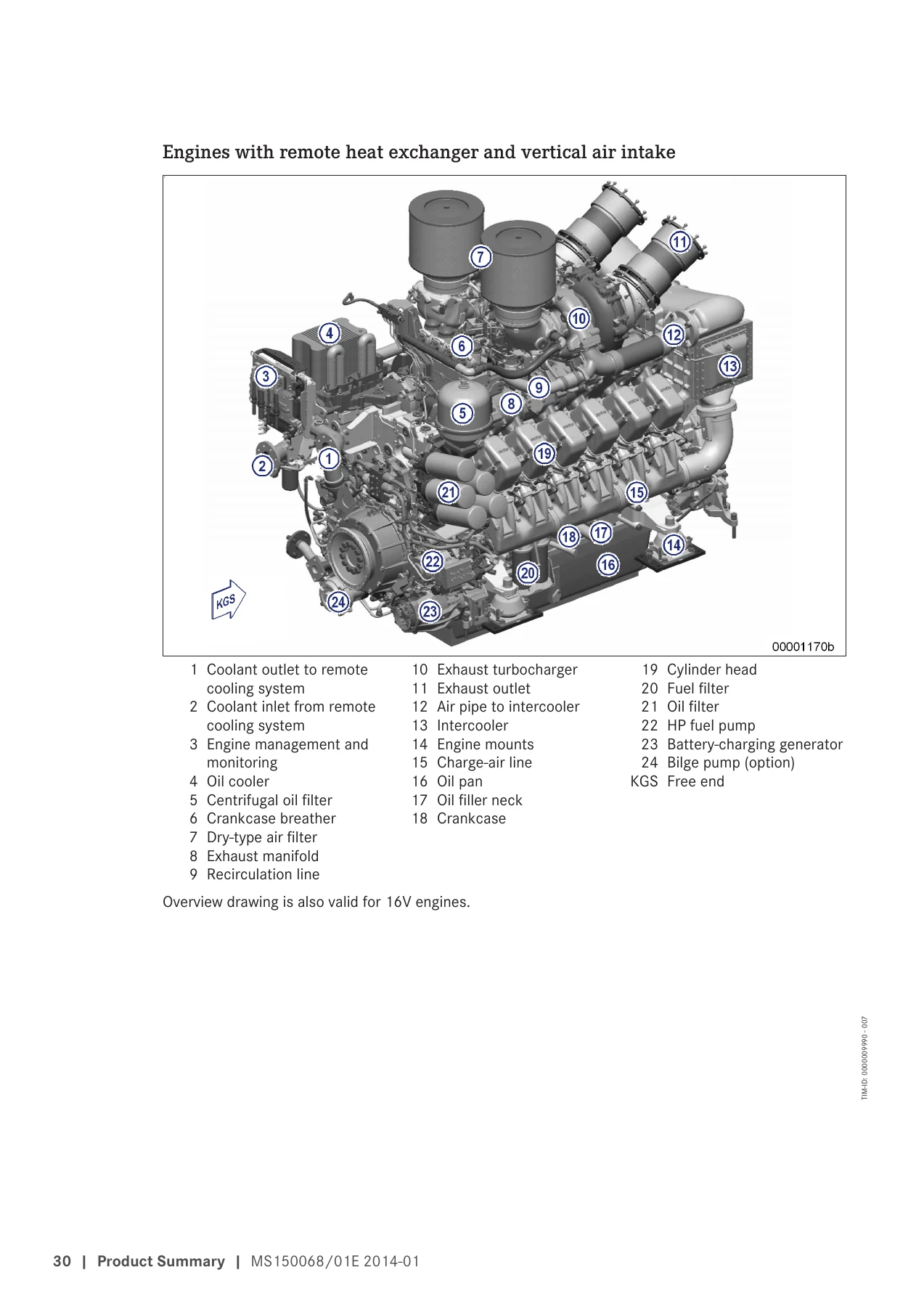
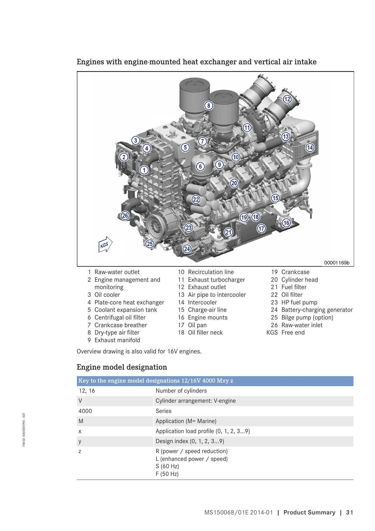
2.1.2 Engine layoutp. 28
2.1.3 Overview of sensors and actuatorsp. 32
+2.2 Engine Side and Cylinder Designationsp. 52
2.2.1 Engine side and cylinder designationsp. 52
+2.3 Main Engine Dimensionsp. 53
2.3.1 Engine – Main dimensionsp. 53
+2.4 Firing Sequencep. 55
+2.5 Technical Datap. 56
2.5.1 12V 4000 M23F engine data, RheinSchUO, stage II, IMO Tier IIp. 56
2.5.2 12V 4000 M23S engine data, RheinSchUO, stage II, IMO Tier IIp. 59
2.5.3 12V 4000 M23S engine data, IMO Tier II, EPA Tier 2p. 62
2.5.4 16V 4000 M23F engine data, RheinSchUO, stage II, IMO Tier IIp. 65
2.5.5 16V 4000 M23S engine data, RheinSchUO, stage II, IMO Tier IIp. 68
2.5.6 16V 4000 M23S engine data, IMO Tier II, EPA Tier 2p. 71
+3 Operationp. 74
3.1 Controlsp. 74
3.2 Putting the engine into operation after extended out-of-service periods (>3 months)p. 75
3.3 Putting the engine into operation after scheduled out-of-service-periodp. 76
3.4 Starting the enginep. 77
3.5 Operational checksp. 78
3.6 Tasks after extended out-of-service periods (>3 weeks)p. 79
3.7 Checks prior to start-upp. 80
3.8 Fuel treatment system – Putting into operationp. 81
3.9 Fuel treatment system – Switching onp. 84
3.10 Fuel treatment system – Shutdownp. 85
3.11 Stopping the enginep. 86
3.12 Emergency engine stopp. 87
3.13 After stopping the enginep. 88
3.14 Plant – Cleaningp. 89
+4 Maintenancep. 90
4.1 Maintenance task reference table [QL1]p. 90
+5 Troubleshootingp. 92
5.1 Troubleshootingp. 92
5.2 Fuel treatment system – Troubleshootingp. 95
5.3 Engine governor ADEC (ECU 7) fault messages for Series 4000 engines, marine applicationp. 96
5.4 Engine governor ADEC (ECU 7) – Fault codesp. 97
+6 Task Descriptionp. 162
+6.1 Enginep. 162
6.1.1 Engine – Barring manuallyp. 162
6.1.2 Engine – Barring with starting systemp. 164
+6.2 Cylinder Linerp. 165
6.2.1 Cylinder liner – Endoscopic examinationp. 165
6.2.2 Instructions and comments on endoscopic and visual examination of cylinder linersp. 167
+6.3 Crankcase Breatherp. 169
6.3.1 Crankcase breather – Overviewp. 169
6.3.2 Crankcase breather – Oil mist fine separator replacementp. 171
+6.4 Valve Drivep. 172
6.4.1 Valve gear – Lubricationp. 172
6.4.2 Valve clearance – Check and adjustmentp. 173
6.4.3 Cylinder head cover – Removal and installationp. 176
+6.5 Injection Pump / HP Pumpp. 177
6.5.1 HP pump – Filling with engine oilp. 177
6.5.2 HP pump – Relief bore checkp. 178
+6.6 Injection Valve / Injectorp. 179
6.6.1 Injector – Replacementp. 179
6.6.2 Injector – Removal and installationp. 180
+6.7 Fuel Filterp. 185
6.7.1 Supplementary fuel filter – Overviewp. 185
6.7.2 Additional fuel filter – Replacementp. 186
6.7.3 Fuel filter – Replacementp. 187
6.7.4 Fuel system – Ventingp. 189
6.7.5 Fuel prefilter – Differential pressure check and adjustment of gaugep. 190
6.7.6 Fuel prefilter – Drainingp. 191
6.7.7 Fuel prefilter – Flushingp. 193
6.7.8 Fuel prefilter with water separator – Filter element replacementp. 195
6.7.9 Fuel prefilter with water separator – O-ring replacement in rotary slide valvep. 197
+6.8 Exhaust Turbochargerp. 198
6.8.1 Overview of turbochargerp. 198
6.8.2 Compressor wheel – Cleaningp. 205
+6.9 Charge-Air Coolingp. 213
6.9.1 Intercooler – Checking condensate drain for water discharge and obstructionp. 213
+6.10 Air Filterp. 214
6.10.1 Air filter – Replacementp. 214
6.10.2 Air filter – Removal and installationp. 215
+6.11 Air Intakep. 216
6.11.1 Service indicator – Signal ring position check (optional)p. 216
+6.12 Starting Equipmentp. 217
6.12.1 Starter – Condition checkp. 217
+6.13 Lube Oil System, Lube Oil Circuitp. 218
6.13.1 Engine oil – Level checkp. 218
6.13.2 Engine oil – Changep. 219
6.13.3 Engine oil – Sample extraction and analysisp. 221
+6.14 Oil Filtration / Coolingp. 223
6.14.1 Engine oil filter ‒ Replacementp. 223
6.14.2 Oil indicator filter – Cleaning and checkp. 225
6.14.3 Centrifugal oil filter – Cleaning and filter sleeve replacementp. 227
+6.15 Coolant Circuit, General, High-Temperature Circuitp. 230
6.15.1 Drain and vent pointsp. 230
6.15.2 Engine coolant level – Checkp. 234
6.15.3 Engine coolant – Changep. 235
6.15.4 Engine coolant – Drainingp. 236
6.15.5 Engine coolant – Fillingp. 239
6.15.6 HT coolant pump – Relief bore checkp. 241
6.15.7 Engine coolant – Sample extraction and analysisp. 242
6.15.8 Engine coolant filter – Replacementp. 243
6.15.9 Preheating unitp. 244
6.15.10 Preheater – Overhaulp. 247
6.15.11 Preheater – Function and leak-tightness checkp. 248
+6.16 Raw Water Pump with Connectionsp. 249
6.16.1 Raw water pump – Relief bore checkp. 249
+6.17 Engine Mounting / Supportp. 250
6.17.1 Engine mounting – Checkp. 250
+6.18 Battery-Charging Generatorp. 251
6.18.1 Battery-charging generator drive – Coupling condition checkp. 251
+6.19 Auxiliary PTOp. 252
6.19.1 Bilge pump – Relief bore checkp. 252
+6.20 Fuel Supply Systemp. 253
6.20.1 Water drain valve – Checkp. 253
6.20.2 Differential pressure gauge – Checkp. 254
6.20.3 Water level probe (3-in-1 rod electrode) – Checkp. 255
6.20.4 Pump capacity – Checkp. 256
6.20.5 Coalescer filter element – Replacementp. 257
+6.21 Wiring (General) for Engine/Gearbox/Unitp. 259
6.21.1 Engine wiring harness – Overviewp. 259
6.21.2 Engine wiring – Checkp. 265
+6.22 Accessories for (Electronic) Engine Governor / Control Systemp. 266
6.22.1 CDC parameters – Resetp. 266
6.22.2 Limit switch for start interlock ‒ Checkp. 267
6.22.3 Engine Control Unit ECU 7 – Checking plug connectionsp. 268
6.22.4 Engine Monitoring Unit EMU 7 – Plug connection checkp. 269
6.22.5 Interface module EIM plug connections – Checkp. 270
6.22.6 Engine Control Unit ECU 7 – Removal and installationp. 271
6.22.7 EMU 7 – Removal and installationp. 272
6.22.8 Engine Interface Module EIM – Removal and installationp. 273
6.22.9 Diagnostic features of EIMp. 274
+7 Appendix Ap. 277
7.1 Abbreviationsp. 277
7.2 MTU contact persons/service partnersp. 279
+8 Appendix Bp. 280
8.1 Special Toolsp. 280
8.2 Indexp. 285
Technical Data Included
The MTU 12V/16V 4000 M23F M23S Diesel Engine Operating Instructions manual includes full technical data tables for each variant: rated engine speed (1500/1800 rpm depending on variant), continuous power ratings from 1140 kW to 1840 kW, 90-degree V cylinder arrangement, 170 mm bore, 210 mm stroke, and 4.77-liter cylinder displacement, plus firing speed ranges and firing order tables.
Why Technicians Rely on This Manual
Marine diesel engines like the MTU 4000 series run continuous-duty schedules where a wrong maintenance interval or a missed safety step has real consequences. This operating instructions manual keeps every procedure — from barring the engine manually to replacing injectors, filters, and turbocharger components — tied to MTU’s own task descriptions, so the work matches how the engine was designed to be serviced. Whether you’re commissioning a new installation, running scheduled maintenance, or chasing an ADEC ECU 7 fault code, this manual gives you the documented procedure rather than trial and error.
Delivery is instant: after checkout you receive the complete MTU 12V/16V 4000 M23F M23S Diesel Engine Operating Instructions PDF for immediate download. There’s no shipping wait — read it on a laptop, tablet, or phone in the engine room, or print out the sections you need at the workbench.


Reviews
There are no reviews yet.