
★ TRUSTED BY 321,897+ PROFESSIONALS WORLDWIDE
🏢
Trusted Business
Verified & Licensed
🛡️
Virus Free Files
100% Safe Downloads
🔒
Secure Payment
SSL Protected
Instant Delivery
Available Immediately
Sale!

MTU 12V & 16V 4000 G23 G43 G63 G83 G83L Diesel Engine Operating Instructions Manual

Original price was: $29.95.Current price is: $17.95.

Genuine MTU Operating Instructions manual for 12V and 16V 4000 series G23, G43, G63, G83 and G83L diesel genset engines – covers safety, technical data, operation, maintenance, troubleshooting and task procedures in one 196-page PDF download.

Instant PDF Download
Available immediately
💾
Save to Your Device
Download & keep forever
🛡️
Antivirus Scanned
100% virus-free
🌍
Trusted Worldwide
175,000+ customers

Description

MTU 12V & 16V 4000 G23, G43, G63, G83, G83L Diesel Engine Operating Instructions Manual

This MTU 12V and 16V 4000 G23 G43 G63 G83 G83L Diesel Engine Operating Instructions Manual (document M015710/04E) is the complete operator and maintenance reference for MTU’s Series 4000 Gx3(L) diesel genset engines. Running to 196 pages, it walks you through everything from crankshaft transport locking and startup safety through full technical data tables, day-to-day operation, scheduled maintenance, troubleshooting, and step-by-step task procedures for the 12V and 16V configurations in the G23, G43, G63, G83 and G83L application variants.

  • Manual type: Operating Instructions
  • Brand / Series: MTU Series 4000 (12V and 16V Gx3/Gx3L)
  • Language: English
  • Page count: 196 pages
  • File format: PDF (instant download)
  • Document number: M015710/04E
  • Edition / revision date: 2012-09, revised 2016-03

Chapters Covered

  • 1 Safety
    • 1.1 General conditions
    • 1.2 Personnel and organizational requirements
    • 1.3 Transport
    • 1.4 Crankshaft transport locking device
    • 1.5 Safety regulations for startup and operation
    • 1.6 Explosion hazard when removing inspection port cover on engine
    • 1.7 Safety regulations for maintenance and repair work
    • 1.8 Auxiliary materials, fluids and lubricants, fire prevention and environmental protection
    • 1.9 Conventions for safety instructions in the text
  • 2 General Information
    • 2.1 Engine side and cylinder designations
    • 2.2 Engine layout
    • 2.3 Sensors, actuators and injectors – Overview
  • 3 Technical Data
    • 3.1-3.10 16V and 12V 4000 Gx3 engine data for continuous and standby operation, fuel-consumption and exhaust-emission optimized variants (EPA stage 2 / TA-Luft)
    • 3.11 Final compression pressure
    • 3.12 Firing order
    • 3.13 Engine – Main dimensions
  • 4 Operation
    • 4.1-4.2 Putting the engine into operation after out-of-service periods
    • 4.3 Start engine in manual mode (testing mode)
    • 4.4 Safety system – Override
    • 4.5 Starting the engine in emergency situations (override mode)
    • 4.6 Operational checks
    • 4.7 Stop engine in manual mode (testing mode)
    • 4.8 Emergency stop
    • 4.9-4.10 After stopping the engine
    • 4.11 Plant cleaning
  • 5 Maintenance
    • 5.1 Maintenance task reference table [QL1]

    IMAGES PREVIEW

    MTU 12V & 16V 4000 G23 G43 G63 G83 G83L Diesel Engine Operating Instructions Manual — PDF page 1 preview
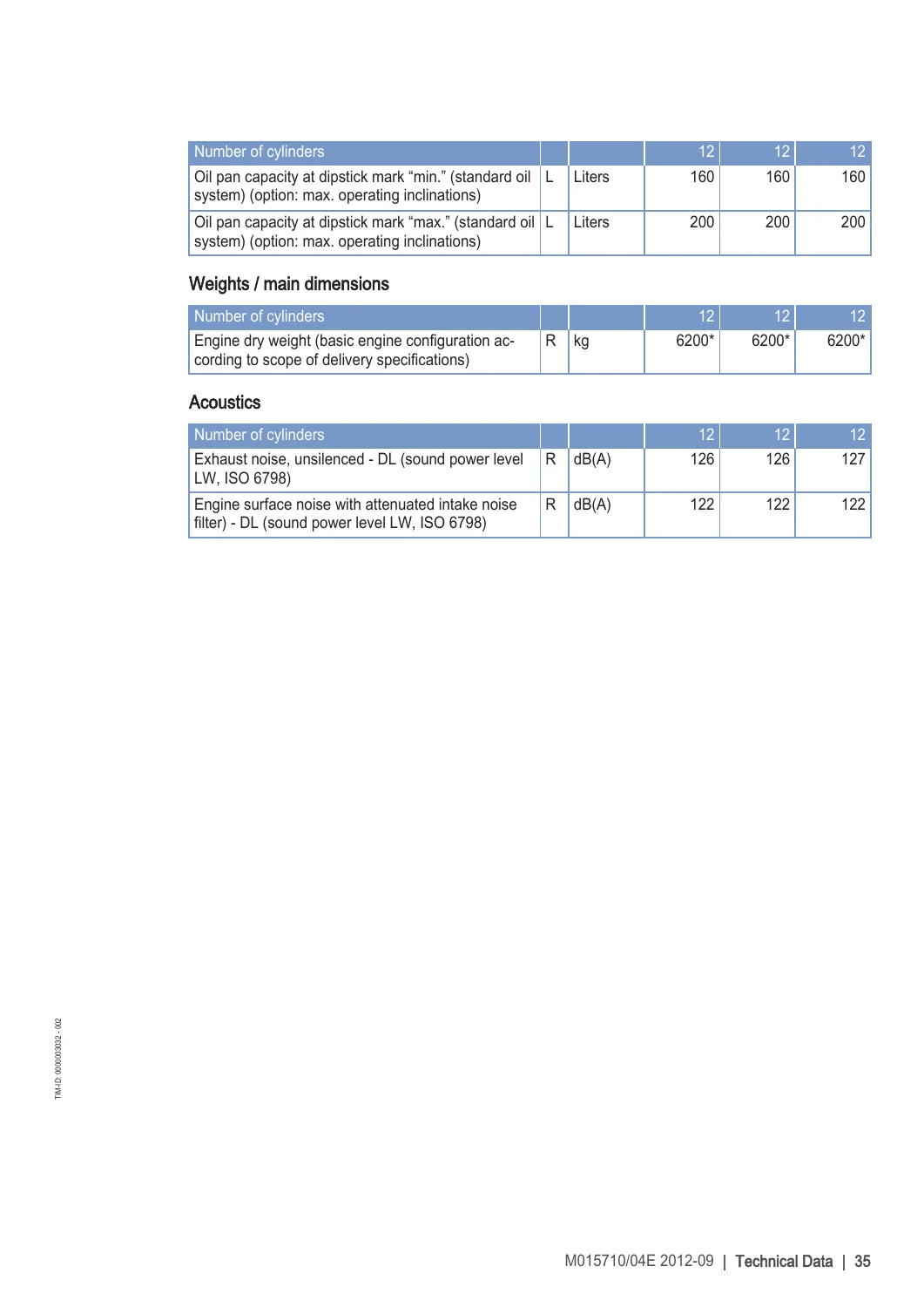
    MTU 12V & 16V 4000 G23 G43 G63 G83 G83L Diesel Engine Operating Instructions Manual — PDF page 20 preview
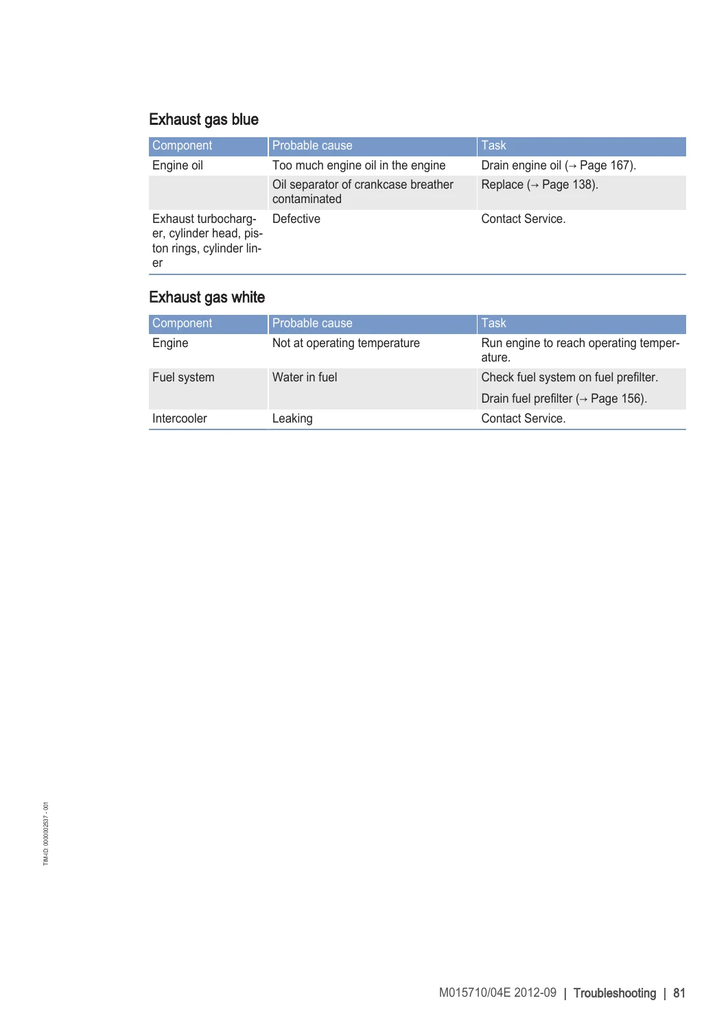
    MTU 12V & 16V 4000 G23 G43 G63 G83 G83L Diesel Engine Operating Instructions Manual — PDF page 66 preview

  • 6 Troubleshooting
    • 6.1 Troubleshooting
    • 6.2 Engine governor ADEC (ECU 7) fault messages for Series 4000 genset engines
  • 7 Task Description
    • 7.1 Engine (barring, test run)
    • 7.2 Cylinder liner endoscopic examination
    • 7.3 Crankcase breather
    • 7.4 Valve drive / valve clearance
    • 7.5-7.6 Injection pump / HP pump / injectors
    • 7.7-7.8 Fuel system and fuel filters
    • 7.9-7.10 Charge-air cooling and air filter
    • 7.11 Air intake service indicator
    • 7.12 Starting equipment (air starter)
    • 7.13-7.14 Lube oil system, oil filtration and cooling
    • 7.15-7.16 Coolant circuits (HT and LT)
    • 7.17-7.18 Belt drive and battery-charging generator
    • 7.19 Engine mounting
    • 7.20 Wiring (general)
    • 7.21 Accessories for electronic engine governor / control system
  • 8 Appendix A
    • 8.1 Abbreviations
    • 8.2 MTU contact persons/service partners
  • 9 Appendix B
    • 9.1 Special tools
    • 9.2 Index

Together these chapters give a technician or plant operator everything needed to commission, run, and keep a 12V or 16V 4000 Gx3(L) genset engine within its rated operating envelope – from the correct startup sequence and safety precautions through the exact technical limits, coolant and lube-oil specifications, and the individual maintenance and repair tasks called out in the reference table.

Technical Data Highlights

The Technical Data chapter of this MTU 12V and 16V 4000 Operating Instructions Manual lists complete performance and design figures for each application group (3A continuous, 3B continuous variable, 3D standby, fuel-consumption optimized and exhaust-emission optimized/EPA stage 2/TA-Luft variants). Shared engine architecture across the G23/G43/G63/G83/G83L range includes a 170 mm bore, 210 mm stroke, 16.5:1 compression ratio (16.4:1 for the G83L standby ratings), 4.77 liter per-cylinder displacement, and rated speeds of 1500 or 1800 rpm depending on model and duty cycle. Continuous power ratings for the 16V range from roughly 1560 to 1710 kW under ISO 3046 conditions. The manual also documents coolant temperature limits for both HT and LT circuits, lube-oil operating pressures and temperatures, fuel system pressure limits, engine oil and coolant capacities, dry weight (approximately 7700 kg for the 16V), main dimensions (12V approx. 2520 x 1660 x 2160 mm; 16V approx. 2990 x 1660 x 2160 mm), firing orders for 8V through 20V configurations, and exhaust/surface noise levels.

Complete PDF Bookmark Tree

Complete Bookmarks

The complete bookmarks in the “MTU 12V & 16V 4000 G23 G43 G63 G83 G83L Diesel Engine Operating Instructions Manual” are as follows:

Operating Instructionsp. 1
Table of Contentsp. 2
1 Safety
1.1 General conditions
1.2 Personnel and organizational requirements
1.3 Transport
1.4 Crankshaft transport locking device
1.5 Safety regulations for startup and operation
1.6 Explosion hazard when removing inspection port cover on engine
1.7 Safety regulations for maintenance and repair work
1.8 Auxiliary materials, fluids and lubricants, fire prevention and environmental protection
1.9 Conventions for safety instructions in the text
2 General Informationp. 4
2.1 Engine side and cylinder designationsp. 4
2.2 Engine layoutp. 5
2.3 Sensors, actuators and injectors – Overviewp. 6
3 Technical Datap. 10
3.1 16 V 4000 Gx3 engine data: Continuous operation 3A, optimized fuel consumptionp. 10
3.2 12 V 4000 Gx3 engine data: Continuous operation, variable 3B, optimized fuel consumptionp. 13
3.3 12 V 4000 Gx3 engine data: Continuous operation, variable 3B, optimized exhaust emissions (TA-Luft)p. 17
3.4 16 V 4000 Gx3 engine data: Continuous operation, variable 3B, optimized fuel consumptionp. 21
3.5 12/16 V 4000 Gx3 engine data: Continuous operation, variable 3B, optimized exhaust emissions (EPA stage 2)p. 25
3.6 12V 4000 Gx3 engine data: Standby operation 3D, optimized fuel consumptionp. 29
3.7 16 V 4000 Gx3 engine data: Standby operation 3D, optimized fuel consumptionp. 33
3.8 12/16 V 4000 Gx3 engine data: Standby operation 3D, optimized exhaust emissions (EPA stage 2)p. 37
3.9 16 V 4000 G83L engine data: Standby operation 3D, optimized fuel consumptionp. 41
3.10 16 V 4000 G83L engine data: Standby operation 3D, optimized exhaust emissions (EPA stage 2)p. 45
3.11 Final compression pressurep. 49
3.12 Firing orderp. 50
3.13 Engine – Main dimensionsp. 51
4 Operationp. 52
4.1 Putting the engine into operation after extended out-of-service periods (>3 months)p. 52
4.2 Putting the engine into operation after scheduled out-of-service-periodp. 53
4.3 Start engine in manual mode (testing mode)p. 54
4.4 Safety system – Overridep. 55
4.5 Starting the engine in emergency situations (override mode)p. 56
4.6 Operational checksp. 57
4.7 Stop engine in manual mode (testing mode)p. 58
4.8 Emergency stopp. 59
4.9 After stopping the engine – Engine remains ready for operationp. 60
4.10 After stopping the engine – putting the engine out of servicep. 61
4.11 Plant cleaningp. 62
5 Maintenancep. 63
5.1 Maintenance task reference table [QL1]p. 63
6 Troubleshootingp. 64
6.1 Troubleshootingp. 64
6.2 Engine governor ADEC (ECU 7) for Series 4000 genset engines – Fault messagesp. 67
7 Task Descriptionp. 116
7.1 Enginep. 116
7.1.1 Engine – Barring manuallyp. 116
7.1.2 Engine – Barring with starting systemp. 117
7.1.3 Engine – Test runp. 118
7.2 Cylinder Linerp. 119
7.2.1 Cylinder liner – Endoscopic examinationp. 119
7.2.2 Instructions and comments on endoscopic and visual examination of cylinder linersp. 121
7.3 Crankcase Breatherp. 123
7.3.1 Crankcase breather – Oil separator element replacement, diaphragm check and replacementp. 123
7.4 Valve Drivep. 125
7.4.1 Valve gear – Lubricationp. 125
7.4.2 Valve clearance – Check and adjustmentp. 126
7.4.3 Cylinder head cover – Removal and installationp. 129
7.5 Injection Pump / HP Pumpp. 130
7.5.1 HP pump – Filling with engine oilp. 130
7.6 Injection Valve / Injectorp. 131
7.6.1 Injector – Replacementp. 131
7.6.2 Injector – Removal and installationp. 132
7.7 Fuel Systemp. 137
7.7.1 Fuel system – Ventingp. 137
7.8 Fuel Filterp. 138
7.8.1 Fuel filter – Replacementp. 138
7.8.2 Fuel prefilter cleaningp. 139
7.8.3 Fuel prefilter – Differential pressure gauge check and adjustmentp. 140
7.8.4 Fuel prefilter – Drainingp. 141
7.8.5 Fuel prefilter – Flushingp. 142
7.8.6 Fuel prefilter – Filter element replacementp. 144
7.9 Charge-Air Coolingp. 146
7.9.1 Intercooler – Checking condensate drain for coolant discharge and obstructionsp. 146
7.10 Air Filterp. 147
7.10.1 Air filter – Replacementp. 147
7.10.2 Air filter – Checkp. 148
7.10.3 Air filter – Removal and installationp. 149
7.11 Air Intakep. 150
7.11.1 Service indicator – Signal ring position check (optional)p. 150
7.12 Starting Equipmentp. 151
7.12.1 Air starter – Manual operationp. 151
7.13 Lube Oil System, Lube Oil Circuitp. 152
7.13.1 Engine oil – Changep. 152
7.13.2 Engine oil – Level checkp. 154
7.13.3 Engine oil – Sample extraction and analysisp. 155
7.14 Oil Filtration / Coolingp. 156
7.14.1 Engine oil filter – Replacementp. 156
7.14.2 Oil indicator filter – Checkp. 157
7.14.3 Centrifugal oil filter – Cleaning and filter sleeve replacementp. 159
7.15 Coolant Circuit, General, High-Temperature Circuitp. 161
7.15.1 Engine coolant – Level checkp. 161
7.15.2 Engine coolant – Changep. 162
7.15.3 Engine coolant – Drainingp. 163
7.15.4 Engine coolant – Fillingp. 164
7.15.5 Engine coolant pump – Relief bore checkp. 167
7.15.6 Engine coolant – Sample extraction and analysisp. 168
7.16 Low-Temperature Circuitp. 169
7.16.1 Charge-air coolant – Level checkp. 169
7.16.2 Charge-air coolant – Changep. 170
7.16.3 Charge-air coolant – Drainingp. 171
7.16.4 Charge-air coolant – Fillingp. 172
7.16.5 Charge-air coolant pump – Relief bore checkp. 175
7.17 Belt Drivep. 176
7.17.1 Drive belt – Condition checkp. 176
7.18 Battery-Charging Generatorp. 177
7.18.1 Battery-charging generator drive – Drive belt tension adjustmentp. 177
7.18.2 Battery-charging generator drive – Drive belt replacementp. 178
7.19 Engine Mounting / Supportp. 179
7.19.1 Engine mounting – Checkp. 179
7.20 Wiring (General) for Engine/Gearbox/Unitp. 180
7.20.1 Engine wiring – Checkp. 180
7.21 Accessories for (Electronic) Engine Governor / Control Systemp. 181
7.21.1 Engine governor and connectors – Cleaningp. 181
7.21.2 Engine governor – Checking plug-in connectionsp. 182
7.21.3 ECU 7 engine governor – Removal and installationp. 183
8 Appendix Ap. 184
8.1 Abbreviationsp. 184
8.2 MTU contact persons/service partnersp. 187
9 Appendix Bp. 188
9.1 Special Toolsp. 188
9.2 Indexp. 194

Why Technicians Rely on This Manual

Because these Gx3(L) genset engines are built and tuned differently across continuous, variable and standby duty ratings, working from the correct application-group data in this MTU 12V and 16V 4000 G23 G43 G63 G83 G83L manual is essential – using the wrong pressure, temperature or capacity figure for your specific engine variant can lead to incorrect maintenance decisions or out-of-spec operation. This Operating Instructions Manual keeps every rating, limit and procedure for your exact configuration in one place.

Get instant access to the complete MTU 12V and 16V 4000 G23 G43 G63 G83 G83L Diesel Engine Operating Instructions Manual as a downloadable PDF. There’s no waiting on shipping and no printed book to store – the file lands in your inbox the moment payment is confirmed, ready to read on a laptop, tablet or phone in the field, or printed at your own workshop for a bench copy.
Reviews

There are no reviews yet.

Be the first to review “MTU 12V & 16V 4000 G23 G43 G63 G83 G83L Diesel Engine Operating Instructions Manual”

What Our Customers Say

★★★★★ Live reviews from customers
Loading customer reviews...
0
    0
    Your Cart
    Your cart is emptyReturn to Shop
    🛒
    Recently Purchased
    🕒 verified order