
MAN Diesel L16/24 GenSet Engine Operation and Maintenance Manual – Complete PDF Workshop Guide
Original price was: $79.95.$49.95Current price is: $49.95.
Complete 726-page operation and maintenance manual for the MAN Diesel L16/24 GenSet engine. Covers operation, maintenance, troubleshooting, fuel oil, lubricating oil, cooling water, cylinder head, piston, camshaft, turbocharger, control and safety systems, tools and more. Instant PDF download.
Description
MAN Diesel L16/24 GenSet Engine Operation and Maintenance Manual
This is the complete operation and maintenance manual for the MAN Diesel L16/24 GenSet engine, covering all aspects of operating, maintaining, troubleshooting and overhauling the L16/24 four-stroke diesel engine. Across 726 pages and 20 technical sections, this manual delivers the procedures, working cards, tightening torques, pressure and tolerance values, and system descriptions needed to keep the L16/24 generating set running reliably in marine and stationary power applications.
File Details
- Manual Type: Engine Operation and Maintenance Manual
- Brand: MAN Diesel (MAN B&W Diesel A/S)
- Model: L16/24
- Language: English
- Page Count: 726
- File Format: PDF
- Document Editions: Multiple editions throughout, including 17H, 02, 03, 03H, 05H, 06H, 08H, 10H, 12H, 13, 14, 15H, 24H, 30H, 57
Chapters Covered
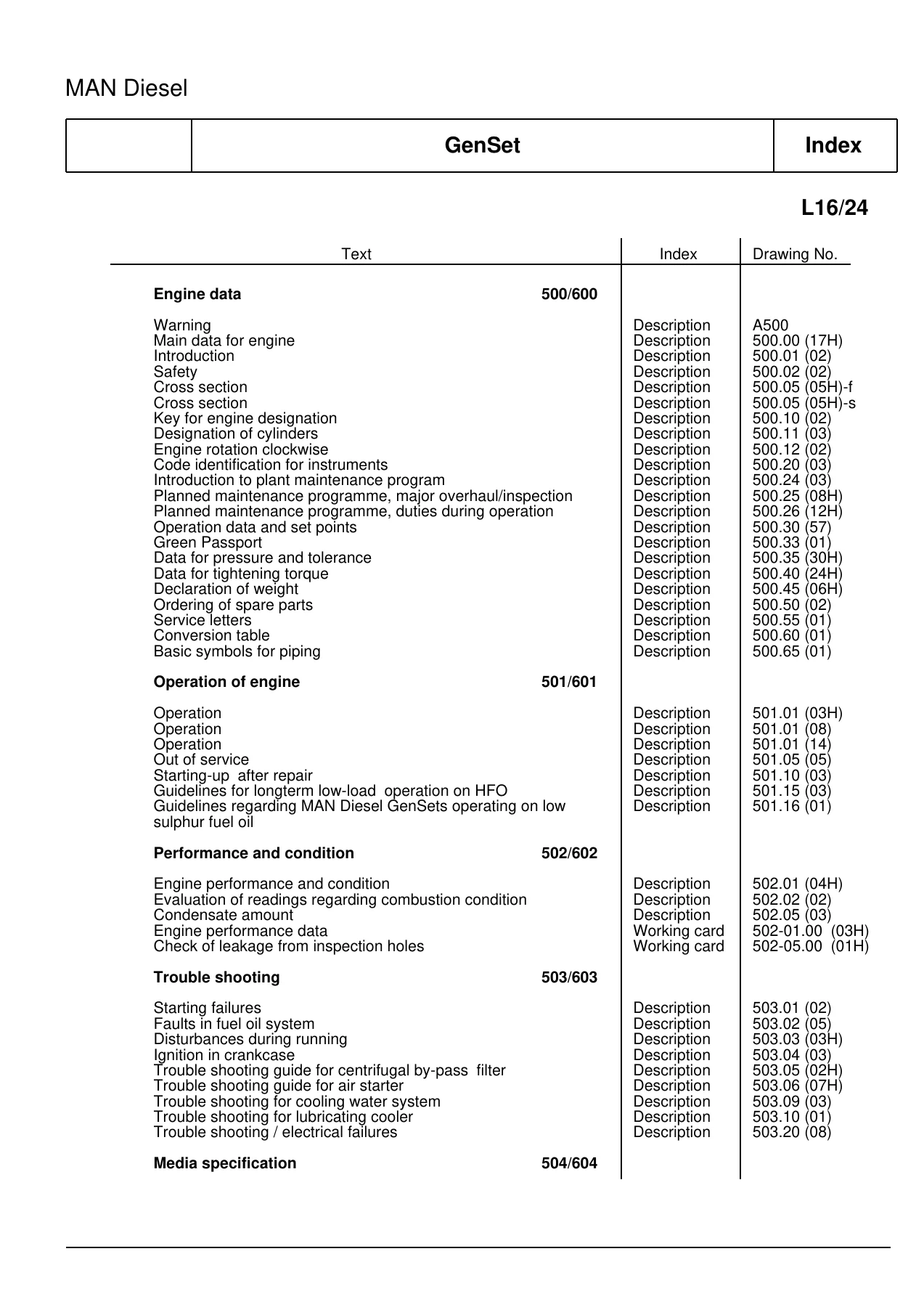
- 500/600 — General
- 501/601 — Operation
- 502/602 — Engine Performance and Condition
- 503/603 — Trouble Shooting
- 504/604 — Media Specification
- 505/605 — Cylinder Head
- 506/606 — Piston/Connecting Rod
- 507/607 — Camshaft
- 508/608 — Operating Gear
- 509/609 — Control/Safety
- 510/610 — Crankshaft
- 511/611 — Engine Frame/Oil Pan
- 512/612 — Turbocharger
- 513/613 — Compressed Air System
- 514/614 — Fuel Oil System
- 515/615 — Lubricating Oil System
- 516/616 — Cooling Water System
- 517/617 — Special Equipment
- 519/619 — Specific Plant Information
- 520/620 — Tools
General Information — Sections 500/600
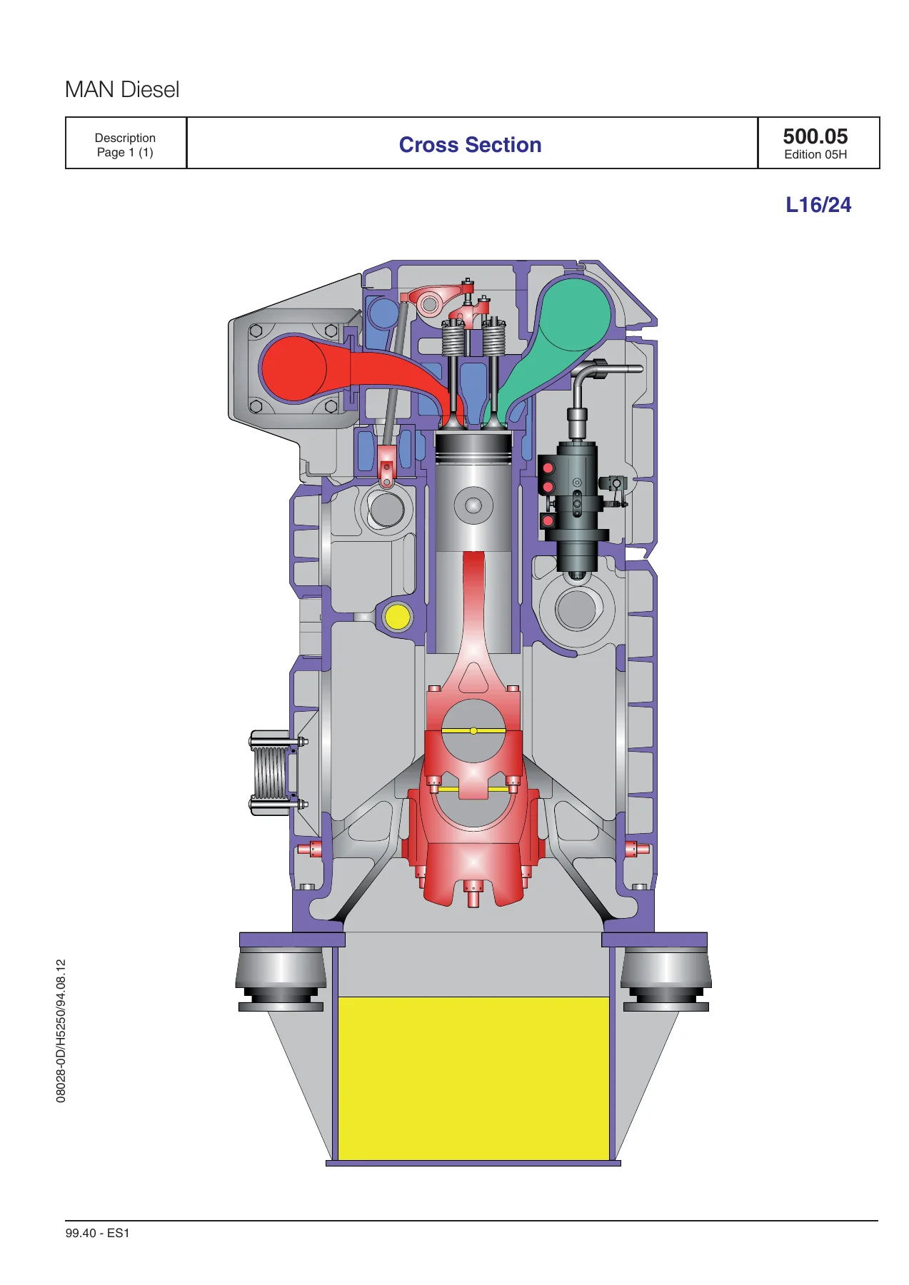
Engine data for the L16/24 including cycle, configuration, bore, stroke, compression ratio, power range and speed. Safety instructions covering general engine room safety, crankcase work, and feel-over sequences. Cross sections show the engine layout. Engine type identification, cylinder designation, and rotation direction are explained. Instrument code identification, planned maintenance programme with major overhaul intervals and duties during operation, operation data and set points with alarm and autostop values, green passport information, pressure and tolerance data, tightening torque data with hydraulic tool pressures and screw-in moments, declaration of weight, spare parts ordering procedure, service letters, conversion tables, and basic symbols for piping.
Operation — Sections 501/601
Preparations for starting the L16/24 engine including lubricating oil system checks, cooling water system preparation, HFO system circulation, starting air system checks, and prelubrication requirements. Starting and stopping procedures for HFO and MDO operation, including preheating requirements. Testing during running, operating parameters, and shutdown procedures. Guidelines for long-term low-load operation on HFO with admissible load/period curves, clean-burning periods, and changeover to MDO. Guidelines for operating on low sulphur fuel oil including viscosity requirements and leak oil considerations.
Engine Performance and Condition — Sections 502/602
Evaluation of readings regarding combustion condition. Performance data and engine condition assessment covering air cooler, fuel injection pump, turbocharger, fuel valves, exhaust valves, air inlet valves, fuel injection pumps, and engine room ventilation. Condensate amount calculation using the nomogram for charge air receiver and air tanks. Working cards for measuring engine performance data and checking leakages from inspection holes.
Troubleshooting — Sections 503/603
Starting failures and their causes. Faults in the fuel oil system. Disturbances during running including exhaust gas temperature deviations, engine speed changes, smoky exhaust, and cooling water temperature issues. Ignition in crankcase with causes and measures. Troubleshooting guides for centrifugal by-pass filter, air starter, cooling water system, and lubricating cooler. Electrical failures covering the safety system and monitoring system with LED indications and error messages.
Media Specification — Sections 504/604
Lubricating oil quality requirements for HFO operation and for MGO/MDO and biofuel operation, including SAE 40 specifications, base oil requirements, additives, detergency, dispersancy, neutralisation capacity, and oil in service limits. Approved lubricating oil table. Lubricating oil types used in the engine. Lubricating oil level in base frame. Specific lubricating oil consumption (SLOC) calculation. Heavy fuel oil quality including specifications, CIMAC recommendations, and supplementary remarks. Marine diesel oil quality. Marine gas oil quality. Analysis data for fuel oils including carbon residue, asphaltenes, diesel index, sulphur, vanadium, sodium, water, ash, silicium and aluminium oxides, viscosity, density, pour point, and flash point. Fuel oil cleaning and purification recommendations. Fresh water system treatment including corrosion protection, inhibitors, and cleaning procedures.
Cylinder Head — Sections 505/605
Cylinder head description with integrated charge air receiver, bore-cooled thick walled bottom, central bore for fuel injection valve, and 4-valve cross flow design. Water jacket function, air inlet and exhaust valves, valve rotators, and replaceable valve seat rings. Working cards for dismantling the cylinder unit, inspection of inlet and exhaust valves and valve guide, reconditioning of valve spindle seat and valve seat ring, valve rotator maintenance, replacement of valve guide, replacement of valve seat ring, inspection of cylinder head cooling water space, assembly of cylinder unit, and mounting of cylinder unit in engine. Spare parts plates with part numbers and quantities.
Piston/Connecting Rod — Sections 506/606
Piston description with oil-cooled composite type, nodular cast iron skirt, forged deformation resistant steel crown, and 2 compression rings plus 1 oil scraper ring. Connecting rod description with die-forged construction, horizontal split big-end, and bored channels for oil supply. Cylinder liner description with special centrifugal cast iron, flange type, and slip-fit flame ring. Working cards for separation and assembly of piston and connecting rod, inspection of piston, inspection of connecting rod, criteria for replacement of connecting rod big-end and main bearing shells, hydraulic tightening of connecting rod screws, in-situ inspection of connecting rod big-end bearing, inspection and honing of cylinder liner, grinding of seal face, and dismantling at low overhaul height.
Camshaft — Sections 507/607
Camshaft and camshaft drive description with two camshafts for inlet/exhaust valves and fuel pumps, located in the engine frame. Working cards for checking camshaft and camshaft drive, inspection and replacement of camshaft bearing, adjustment of camshaft for valve and injection timing with plunger lift values. Spare parts plates for intermediate wheel, valve camshaft, and injection camshaft.
Operating Gear — Sections 508/608
Operating gear description for valves and fuel injection pumps, including roller guides, valve actuating gear, and rocker arms. Working cards for inspection of valve roller guide, control of valve clearance, and safe valve adjustment. Spare parts plates for roller guide and push rods.
Control/Safety — Sections 509/609
Safety, control and monitoring system description. Lambda controller purpose and functioning. Communication from the GenSet including MODBUS protocol, addressing, and data format. Working cards for functional test and adjustment of safety, alarm and monitoring equipment, function test of shutdown, adjustment and test of analogue pressure transmitter, temperature transmitter, tacho and proximity sensors, mounting and adjustment of pick-ups, and adjustment of lambda controller. Spare parts plates for governor and governor drive, regulating device, instruments, level switch in oil sump, fuel oil leakage alarm, monitoring box, terminal box, digital load sharing and speed control, alarm panel, output module, APM motor control, valve control box, prelubricating oil pump starters, converter, and oil mist detector.
Crankshaft — Sections 510/610
Crankshaft and main bearings description with one-piece forging, underslung bearings, trimetal main bearings with running layer, counterweights, and gear wheel for camshaft drive. Vibration damper description with primary and secondary parts, leaf spring packs, and oil-filled chambers. Working cards for checking alternator/crankshaft alignment (autolog), inspection of main and guide bearing shells, and vibration damper inspection. Spare parts plates for crankshaft, flywheel with gear rim, and vibration damper/tuning wheel.
Engine Frame/Oil Pan — Sections 511/611
Engine frame and base frame description with monobloc cast iron engine frame, underslung crankshaft main bearings, and base frame acting as lubricating oil reservoir. Working card for functional test of crankcase safety relief valves. Spare parts plates for frame with main bearings, front end box, covers on frame, and base frame.
Turbocharger — Sections 512/612
Turbocharger system description with constant pressure system, exhaust gas receiver, turbocharger, charging air cooler, and charging air receiver. Working cards for overhaul of charging air cooler, exhaust pipe compensator, and cleaning the turbine (dry cleaning). Spare parts plates for charging air cooler, exhaust pipe arrangement, mounting of turbocharger, connection pipe, blowgun for dry cleaning, heat insulation of exhaust pipes, cover of exhaust pipes, heat insulation and cover before turbocharger, charge air pipes, oil drain from turbocharger, mounting of charge air cooler, and control air for preheating valve.
Compressed Air System — Sections 513/613
Compressed air system description with starting system, control system, safety system, and jet assist system. Pneumatic start sequence. Working cards for air filter cleaning, overhaul/test/inspection of air starter, emergency starting valve, and check of compressed air piping system. Spare parts plates for air starter, main stop valve, air filter, pressure reduction valve, turning gear with attachment, overspeed stop valve, arrangement of jet system, and starting air receiver.
Fuel Oil System — Sections 514/614
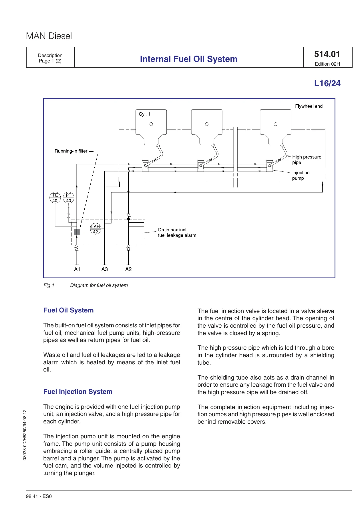
Internal fuel oil system description with inlet pipes, mechanical fuel pump units, high-pressure pipes, return pipes, and leakage alarm. Fuel injection system with one pump unit, injection valve, and high-pressure pipe per cylinder. Running-in filter. Working cards for dismounting/mounting of fuel injection pump (L’Orange and Woodward), disassembly/assembly and repair of fuel injection pump (Woodward and L’Orange), fuel injection valve (L’Orange and Woodward), and check of fuel oil piping system. Spare parts plates for fuel injection pump, fuel injection valve, fuel injection pipe, safety filter, fuel oil arrangement, and fuel injection pump connections.
Lubricating Oil System — Sections 515/615
Internal lubricating oil system description with system flow, lubricating points for turbocharger, main bearings, camshaft drive, governor drive, rocker arms, and camshaft. Lubricating oil pump, cooler, thermostatic valve, filter, and pre-lubricating pump. Working cards for lubricating oil pump, prelubricating pump, lubricating oil filter, thermostatic valve, check of lubricating oil piping system, lubricating oil cooler, and centrifugal bypass filter. Spare parts plates for lubricating oil pump, lubricating oil filter, prelubricating pump, lubricating oil cooler, centrifugal bypass filter, lubricating oil separator, crankcase venting, and prelubricating oil arrangement.
Cooling Water System — Sections 516/616
Internal cooling water system description with low temperature and high temperature systems, thermostatic valves, and integral cooling water system diagram. Working cards for check of cooling water system, cooling water thermostatic valve, and HT and LT water pumps. Spare parts plates for high- and low-temperature freshwater pumps and cooling water connections.
Special Equipment, Plant Information, and Tools — Sections 517/617, 519/619, 520/620
Kit for complete cylinder unit exchange and kit for cylinder unit. Resilient mounting of generating sets with fitting instructions, replacement of conicals, maintenance of conicals, flexible external connections, and conical element details. Tools section covering function and application of hydraulic tools, hand lever pump, tools for cylinder head, piston/connecting rod/cylinder liner, camshaft and camshaft drive, operating gear for inlet and exhaust valves, crankshaft and main bearings, charge air cooler, fuel oil system and injection equipment, lubricating oil cooler, and hydraulic tools.
Why This Manual Matters for Your L16/24
The MAN Diesel L16/24 is a four-stroke, in-line diesel engine available in 5, 6, 7, 8, and 9 cylinder configurations with a power range of 450–990 kW at 1000/1200 rpm. Whether you operate a GenSet in marine service or a stationary power plant, having the correct procedures and specifications is critical. This manual provides the exact tightening torques, hydraulic tool pressures, pressure and tolerance values, and maintenance intervals that keep the engine within specification. From routine valve clearance checks to complete cylinder unit overhauls, every procedure is documented with step-by-step working cards.
IMAGES PREVIEW
Instant PDF Delivery
This MAN Diesel L16/24 GenSet engine operation and maintenance manual is delivered as an instant PDF download. No shipping, no waiting. Access the complete 726-page document on any device — laptop, tablet, or smartphone. Print the pages you need for the workshop floor. The PDF format makes it easy to search for specific procedures, torque values, or troubleshooting steps when you need them most.
Reviews
There are no reviews yet.